background image

5

VI. Specific Model Data

Mounting

Kooltronic Heat Exchangers have been engineered to be installed easily. To avoid damaging your
Heat Exchanger, please read the following information before installation:

1.

Loosen the two screws on the bottom holding the Mounting Template and Assembly Bracket
(M/TAB) to the unit. Remove the M/TAB.

2.

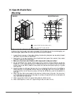
See Figure 1 for proper orientation. Place the M/TAB flush against the outside of the cabinet
to locate cutouts and mounting holes.

3.

Make sure the cutouts don't interfere with components inside your cabinet.

4.

Mount the M/TAB to the outside of the cabinet using all the mounting hardware supplied by
Kooltronic (

1/4

-20 screws/nuts/washers). Preferred positions: one in each corner and two near

center on each side. NOTE: Make sure the screws are inserted with heads toward you. Tighten
nuts securely.

5.

Route the power cord through the top cut out in your cabinet. Mount the unit to the M/TAB by
sliding the slots on the bulkhead into the hooks on the M/TAB. After unit is in place, tighten 2
screws at bottom of unit. These two screws will force the M/TAB into studs on side panel for a
tight seal. 

6.

Attach overflow drain hose supplied to the drain exit at the bottom of the unit.  This hose must
not be elevated above the exit port. Improper mounting will impede the flow of condensate and
may cause internal malfunctions.

7.

Attach supply line to 3/8" O.D. copper tubing Inlet on bottom of unit.

8.

Attach discharge line to 3/8" O.D. copper tubing Outlet on bottom of unit.

Dimensions (inches) are for reference only and are subject to change.

MOUNTING PLAN

(8) .312 

[7.9]

DIA. 

HOLES

8.25

[209.6]

1.12

[28.6]

10.50

[266.7]

1.12

[28.6]

1.75

[44.4]

4.84

[122.9]

10.00

[254.0]

3.79

[96.2]

7.00

[177.8]

1.75

[44.4]

1

2

3.64

[93.0]

8.00

[203.2]

1.25

 [31.8]

1.25

 [31.8]

 2.71

 [68.7]

 6.60

 [167.6]

 6.60

 [167.6]

 6.60

 [167.6]

1.51

[38.4]

1

2

WATER INLET

WATER OUTLET

8.06

[204.8]

10.50

[266.7]

24.02

[610.0]

M/TAB

1

2

WARM AIR RETURN FROM ENCLOSURE

COOL AIR OUTLET TO ENCLOSURE

FIGURE 1

Summary of Contents for KPHE24 Series

Page 1: ...AT EXCHANGER IT IS IMPORTANT THAT THIS MANUAL BE READ AND UNDERSTOOD THOROUGHLY KOOLTRONIC INC 30 Pennington Hopewell Road Pennington NJ 08534 609 466 3400 FAX 609 466 1114 www kooltronic com 900 046 14 7 20 CDR 20272 Find additional information on this model at kooltronic com or use the Technical Documents QR code below Technical Documents ...

Page 2: ...duction Kooltronic Heat Exchangers are designed to provide a cool environment for your electronic or electrical components There are models to fit virtually all sizes and shapes of electrical or electronic enclosures Our closed loop design also ensures that your components will not be exposed to hot dirty operating conditions This Manual provides you with the necessary general information for prop...

Page 3: ...u read and thoroughly understand this Manual Before operating this unit all electrical wiring must be checked to assure the proper connections IV Product Identification and Nameplate Each Kooltronic Heat Exchanger includes an identification nameplate This nameplate provides CAUTION Operate this unit only on the proper voltages and frequencies as noted on the nameplate MODEL NO SERIAL NO MAX CABINE...

Page 4: ...ipated conditions In some cases if sufficiently cold water is available below ambient temperature cooling can be achieved The Heat Exchanger with options Automatic Water Flow Control is shown on Figure 2 Heated Air Blower Water with Heat Load Cold Water Heat Exchanger Cabinet Cooled Air WATER TO AIR A Water to Air Heat Exchanger works by transferring heat of internal air to circulating water resul...

Page 5: ...ut in your cabinet Mount the unit to the M TAB by sliding the slots on the bulkhead into the hooks on the M TAB After unit is in place tighten 2 screws at bottom of unit These two screws will force the M TAB into studs on side panel for a tight seal 6 Attach overflow drain hose supplied to the drain exit at the bottom of the unit This hose must not be elevated above the exit port Improper mounting...

Page 6: ...37 34 Note The rating Watts F is the heat dissipation divided by temperature difference between maximum air temperature in enclosure and water temperature entering the heat exchanger Options Automatic Water Flow Control High Water Level Detector Internal corrosion resistant coatings Low Airflow Detector Other voltages and frequencies Special materials or finishes Special motors line cords or conne...

Page 7: ...ing of Major Component Replacements earlier in this Manual VIII Packing Procedure Keep Heat Exchanger in proper upright position Pack Heat Exchanger in an appropriate carton preferably original carton if possible with adequate internal protective packaging making sure carton is marked properly For local controlled transportation strap carton where possible to a secure part of truck to prevent fall...

Page 8: ...s received by customer Number of parts to be returned Product description model and serial number Reason for return Action requested Contact name telephone FAX numbers and e mail address Pack unit in a suitable container for shipment preferably the original packaging if available All Heat Exchangers must be returned in an upright position properly secured to a pallet Improper packaging may void wa...

Reviews: