background image

Introduction

11

KT-RT-I5 User’s Manual Version 1.0

www.kontron.com

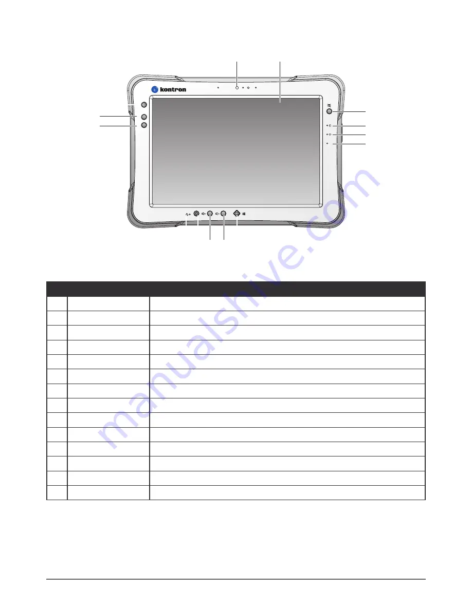
Front View

fn

f1

f2

fn

13

12

14

3

4

5

6

1

8 7

9

10

11

2

Figure 2.  Front View

Table 3.  Front View

No

Item

Description

1

Front camera

2.0 Mega-Pixels camera.

2

Touch screen

5-point capacitive touch.

3

Barcode trigger

If barcode scanner is installed, press to scan.

4

Battery LED

Display battery status, see 

“LED Status”

 on page 12.

5

Wi-Fi LED

The Wi-Fi LED lights to indicate Wi-Fi is enabled.

6

FN LED

The FN LED lights when the function switch on.

7

Home key

Windows

®

 8 home key.

8

Volume increase.

9

Volume -

Volume decrease.

10 Power key

Turns the KT-RT-I5 on or off.

11 Power LED

The power LED lights when the device is on.

12 F2 key

Programmable function key.

13 F1 key

Programmable function key.

14 FN key

Programmable function key.

Summary of Contents for KT-RT-I5

Page 1: ...fn f1 f2 fn fn f1 f2 fn KT RT I5 User s Manual VERSION 1 0 ...

Page 2: ...rors or inaccuracies for this reason Kontron AG expressly informs the user that this manual only contains a general description of technical processes and instructions which may not be applicable in every individual case In cases of doubt please contact Kontron AG This manual is protected by copyright All rights are reserved by Kontron AG Copies of all or part of this manual or translations into a...

Page 3: ...Cleaning and Servicing 4 02 08 Regulatory and Certification 4 02 09 Lithium Battery Safety Statement 5 03 Introduction 03 01 About This Guide 6 03 02 Unpacking the Device 6 03 03 Technical Specifications 6 03 04 KT RT I5 Configuration Options 8 03 05 Parts List 9 03 06 Identifying the Device 10 03 07 Identifying the Digitizer 14 03 08 Dimensions 15 03 09 Touch Screen Features 16 04 Getting Started...

Page 4: ...ulder Strap 29 05 05 Installing the Standard Battery 33 05 06 Removing the Standard Battery 34 05 07 Connecting to a Wireless Network 35 06 Using BIOS Setup Utility 06 01 When to Use the BIOS Setup Utility 37 06 02 Accessing the BIOS Setup Utility 38 06 03 Installation an Operating System 40 06 04 BIOS Passwords 43 06 05 EC and BIOS 45 07 Using the KT RT Control Utility 07 01 Overview 50 08 Troubl...

Page 5: ...expertise not to replace it 01 01 Related Information Current information and manuals are available for download at the following website http www kontron com 01 02 Conventions Bolded or underlined text is used to emphasize the designated information A Note is used to provide additional information for the device or settings A Caution is used to warn against potential hazards or to caution against...

Page 6: ...elf When pulling out or plugging in the connector keep it evenly aligned to prevent bending the connector pins 02 01 Intended Use The KT RT I5 rugged tablet is equipped with multi functional terminals for stationary and mobile applications in industrial environments such as logistics warehousing fleet management manufacturing and the automotive industry Read the safety guidelines thoroughly before...

Page 7: ...ge All Kontron warranties are void Environmental Hazards Do not use the KT RT I5 in locations near with flammable gases or vapor The use of electrical equipment in explosive environments can be dangerous Turn off the device when near a gas station fuel depot chemical plant or a place where blasting operations take place 02 05 Environmental Ambient Temperature The KT RT I5 operates on the basis of ...

Page 8: ...uipment generates uses and can radiate radio frequency energy and if not installed and used in accordance with the instruction manual may cause harmful interference to radio communications Operation of this equipment in a residential area is likely to cause harmful interference in which case the user will be required to correct the interference at his own expense However there is no guarantee that...

Page 9: ...EUT transmitting at the specified power level in different channels The highest SAR value for the device as reported to the FCC is 0 57 W kg when placed next to the body CE Marking This product has passed the CE test for environmental specifications when shielded cables are used for external wiring We recommend the use of shielded cables Please contact your local representative for ordering inform...

Page 10: ... configuration process make sure to inspect all components and accessories Contact your representative if there are any missing or damaged items See Contacting Kontron on page 54 03 03 Technical Specifications Table 1 Technical Specifications Item Description Display 10 1 inch LED Backlight 1920 W x 1200 H WUXGA Touch screen 10 point capacitive touch screen with digitizer Brightness 1000 nits CPU ...

Page 11: ... Docking Connector 12 pin DC IN Jack x1 Micro SIM Card Slot x1 MicroSD Slot x1 Audio Jack x1 headphone microphone combo USB 3 0 x1 type A RS 232 x1 Micro HDMI x1 Ethernet x1 Security TPM TPM 1 2 BIOS On Off for I Os YES Data Collection Camera Front 2 0 Mega Pixels camera Rear 5 0 Mega Pixels camera with LED auxiliary light and Auto focus GNSS YES NFC Optional Barcode Reader Optional Magnetic Strip...

Page 12: ... 810G Method 516 6 Procedure I Procedure V Operation and storage temperature MIL STD 810G Method 501 5 and 502 5 Humidity MIL STD 810G Method 507 5 Humidity Procedure II Aggravated Cycles Fig 507 5 7 IP rating IP65 Operating Temperature Range 20 C 4 F to 60 C 140 F Storage Temperature Range 30 C 22 F to 70 C 158 F Humidity 5 95 without condensation 03 04 KT RT I5 Configuration Options The followin...

Page 13: ...ith the following items All other accessories are sold and ordered separately For help contact your local Kontron sales representative See Contacting Kontron on page 54 fn f1 f2 fn KT RT I5 Power Adapter Digitizer 2 Point Carrying Handle 2 Point Shoulder Strap 4 Point Handstrap Hitch D rings Attaching straps ...

Page 14: ...page 13 for further information 2 Front view See Front View on page 11 for further information 3 Rear view See Rear View on page 14 for further information 4 Right view See Side View on page 13 for further information 5 Rubber bumpers Easy to grip rubber bumpers enable the rugged tablet to withstand shocks and drop for use in demanding environments 6 Bottom view See Bottom View on page 12 for furt...

Page 15: ...er is installed press to scan 4 Battery LED Display battery status see LED Status on page 12 5 Wi Fi LED The Wi Fi LED lights to indicate Wi Fi is enabled 6 FN LED The FN LED lights when the function switch on 7 Home key Windows 8 home key 8 Volume Volume increase 9 Volume Volume decrease 10 Power key Turns the KT RT I5 on or off 11 Power LED The power LED lights when the device is on 12 F2 key Pr...

Page 16: ...ng Low power 15 Off Not charging no battery FN Blue On FN function switch on Blue Off FN function switch off Wi Fi Blue On Wi Fi on Blue Off Wi Fi off Bottom View 1 2 3 Figure 3 Bottom View Table 5 Bottom View No Item Description 1 Docking connector 12 pin connector for docking onto a station 2 Kensington lock Lock the KT RT I5 to a stationary object for security 3 Pass through Dual pass through f...

Page 17: ...er hole Digitizer can be tethered to it 5 Battery switch Switch to ON to provide power from the backup battery 6 Micro SIM slot Insert micro SIM card for 4G LTE communication function 7 USB 3 0 Connect USB devices to the KT RT I5 8 Audio jack Connect a 3 5 mm jack for a headphone or external speakers 9 Ethernet Connect the KT RT I5 to an Ethernet RJ 45 cable 10 DC IN jack Insert power connector to...

Page 18: ...nstalling a barcode reader Optional 4 Fan Embedded fan for cooling 5 Securing holes Secure the bumpers and the D rings for the handstrap and shoulder strap 6 Expansion bay Remove the cover to find the expansion accessory connector 7 Digitizer holder Place digitizer here 03 07 Identifying the Digitizer You can use the digitizer to control your KT RT I5 as with a mouse or keyboard The digitizer is n...

Page 19: ...l Version 1 0 www kontron com 03 08 Dimensions The following image lists the device dimensions without add ons mm inches 28 11 19 5 7 7 fn f1 f2 fn 280 11 195 7 7 Figure 7 Front View Dimensions 2 3 0 9 23 0 9 Figure 8 Side View Dimensions ...

Page 20: ...ing the mouse pointer then left clicking icons on a desktop computer screen The following actions are available through the use of the digitizer Open applications Choose commands in menu Select options in dialog box or drop down menu Drag the scroll bar Drag across the text to select content Place the cursor in a text box before typing A right click is generated by tapping the mouse icon in the sy...

Page 21: ...on on page 54 It is recommended to installing or remove accessories on a clean well lit work surface To protect yourself and the device from electrostatic discharge wear anti static wrist straps or place the device on an anti static mat 04 01 First Time Use 1 Open the left I O compartment cover See Opening the I O Compartment Cover on page 25 2 Switch the switch to the ON position ON OFF SIM Figur...

Page 22: ...y charged the power LED is lit a solid green 1 Flip open the DC IN cover to expose the DC IN jack Figure 10 Opening the DC IN Cover 2 Connect the AC adapter to the DC IN port Figure 11 Connecting the AC Adapter After charging the battery disconnect the AC adapter and close the DC IN cover 1 Insert one end of the cover first and angle the cover to seat it in place 2 Push in the cover to seal the DC...

Page 23: ...Press and hold the power button until the screen lights The device runs through the start up sequence and powers up fn Figure 13 Power On the KT RT I5 Powering Off the Device Start screen Tap Shut down Desktop screen 1 Tap and hold at the bottom left corner of the Desktop screen 2 Tap Shut down or sign out Shut down Both Start screen and Desktop screen 1 Display charm bar and tap Settings 2 Tap Po...

Page 24: ...e left I O compartment cover See Opening the I O Compartment Cover on page 25 3 Locate the micro SIM slot in the left I O parts ON OFF 3 0 SD SIM Left view Micro SIM Slot Figure 14 Left View Locating the Micro SIM Slot 4 Take the micro SIM card from its packaging 5 The micro SIM card has a corner missing Align the SIM card with the slot making sure that the corners match 6 Insert the micro SIM car...

Page 25: ...e I O Compartment Cover on page 25 3 Locate the micro SIM slot in the left I O parts ON OFF 3 0 SD SIM Left view Micro SIM Slot Figure 16 Left View Locating the Micro SIM Slot 4 Press the micro SIM card in and release it The card springs out 5 Grasp the micro SIM card and remove it from the slot Figure 17 Removing the Micro SIM Card 6 Close the left I O compartment cover See Closing the I O Compar...

Page 26: ...cate the microSD slot in the left I O parts ON OFF 3 0 SD SIM Left view MicroSD Slot Figure 18 Left View Locating the MicroSD Slot 3 The microSD card has a beveled edge Align the microSD card with the slot making sure that the corners match 4 Insert the microSD card and press it in until an audible click sounds ON OFF 3 SD SIM Figure 19 Installing the MicroSD Card 5 Close the left I O compartment ...

Page 27: ...page 25 2 Locate the microSD slot in the left I O parts ON OFF 3 0 SD SIM Left view MicroSD Slot Figure 20 Left View Locating the MicroSD Slot 3 Press the microSD card in and release it The card springs out 4 Grasp the microSD card and remove it from the slot Figure 21 Removing the MicroSD Card 5 Close the left I O compartment cover See Closing the I O Compartment Cover on page 26 ...

Page 28: ...y station antennas Near CRT displays that generate strong electromagnetic field noise Move the digitizer away from such locations so it works properly The pointer cannot follow the digitizer movement if you move the digitizer too quickly To make a selection tap the screen once with the digitizer To double click tap twice without pausing To do a right click tap the screen once and hold the tip of t...

Page 29: ... surface 2 Locate the I O compartment cover ON OFF 3 0 SD SIM Left I O Compartment Cover Right I O Compartment Cover Right view Left view Figure 23 Side View Locating the I O Compartment Cover 3 Unlock the latch Only available for the left I O compartment cover Figure 24 Unlocking the Latch 4 Pull out the I O compartment cover Figure 25 Openin the I O Compartment Cover ...

Page 30: ...SIM Left I O Compartment Cover Right I O Compartment Cover Right view Left view Figure 26 Side View Locating the I O Compartment Cover 3 Flip the I O compartment cover and install Figure 27 Installing the I O Compartment Cover 4 Lock the latch Only available for the left I O compartment cover Figure 28 Locking the Latch The I O compartment cover must be inserted correctly to prevent internal damag...

Page 31: ...port USB 2 0 or USB 3 0 devices 1 Open the left I O compartment cover See Opening the I O Compartment Cover on page 25 2 Connect to USB device via USB cable 3 0 SD SIM Figure 29 Connect USB Cabling Connect Ethernet Cabling The KT RT I5 provide have a Ethernet port for connecting Ethernet Use a shielded cable is required to maintain emissions and susceptibility compliance 1 Open the left I O compar...

Page 32: ... Open the left I O compartment cover See Opening the I O Compartment Cover on page 25 2 Connect the audio cable 3 0 Figure 31 Connect Audio Cabling Connect Micro HDMI Cabling Connect to HDMI devices via micro HDMI cable 1 Open the left I O compartment cover See Opening the I O Compartment Cover on page 25 2 Connect micro HDMI cable to micro HDMI port on the KT RT I5 ON OFF 3 SD SIM HDMI Figure 32 ...

Page 33: ...ying Handle and Shoulder Strap The KT RT I5 is equipped with a handstrap a carrying handle and a shoulder strap for convenience and choice Select the accessory that is right for your needs The handstrap can be installed with either the shoulder strap or the carrying handle However the handle and shoulder strap can not be installed together due to space constraints For more information see Connecti...

Page 34: ...all the D rings Make sure the D rings are tightly secured before installing the handstrap Figure 35 Installing the D rings 3 Connect the handstrap on the D rings When the handstrap is installed the digitizer can be placed under the strap Figure 36 Connecting the Handstrap ...

Page 35: ...1 0 www kontron com Removing the Handstrap 1 Unlock the handstrap from the D rings Figure 37 Removing the Handstrap 2 Remove the D rings Figure 38 Removing the D rings 3 Secure the bumper and the KT RT I5 with screws Figure 39 Securing the Screws ...

Page 36: ...mper Metal Loop Figure 40 Connecting the Carrying Handle Removing the Carrying Handle 1 Press in the clips to release them from the metal loop 2 Remove the clips Metal Loop Figure 41 Removing the Carrying Handle Connecting the Shoulder Strap 1 Attach the clips to the metal loop on the bumper Metal Loop Figure 42 Connecting the Shoulder Strap ...

Page 37: ...for both standard and external batteries The external battery is an optional component Only use components specifically designed for this device Contact your local representative for ordering information Make sure the power switch is switched to ON before installing the standard external battery See First Time Use on page 17 1 Place the device display side down on a clean work surface 2 Locate the...

Page 38: ...in place until an audible click is heard Figure 45 Installing the Battery 6 Slide the locking switch on the top left side to lock the battery Figure 46 Locking the Battery Make sure the latch is securely locked to prevent the battery from falling 05 06 Removing the Standard Battery 1 Place the device display side down on a clean work surface 2 Locate the battery Battery Release Button Locking Swit...

Page 39: ...within range of a wireless network Move to a different spot until the Wi Fi icon changes status indicating availability to a wireless network 2 From any screen open the Charms bar by sliding your finger inward from the screen s right edge The Charms bar displays along the screen s right side 3 In the Charms bar tap Settings to open the Settings menu 4 In Settings tap the Network icon to display th...

Page 40: ...assword is required type the password in the Enter the network security key field Alternatively you can also push the WPS button on your router to begin the security handshake 9 Tap Next to finish the connection process You have successfully connected to a wireless network ...

Page 41: ...settings for the Boot and AP menus as well as the device s basic settings the system reads the basic settings during initialization in order to boot correctly 06 01 When to Use the BIOS Setup Utility You need to run the BIOS Setup utility when Restoring to BIOS settings to factory default Modifying specific hardware settings Modifying specific settings to optimize system performance Installing Win...

Page 42: ...un the BIOS Setup Utility use the following procedures 1 Perform one of the following If the KT RT I5 is powered off Press the Power button to start up the device The power LED lights Quickly press and hold the Windows Home key until the BIOS Post screen displays If the KT RT I5 is powered on Press the Power button to shut down the device Quickly press and hold the Windows Home Key until the BIOS ...

Page 43: ...ontron com Due to the device s fast boot up and boot down time there is only a small time frame of a few seconds between the release of the Power button and the opportunity to press the Windows Home key The App Menu displays Figure 51 BIOS Setup Utility App Menu Screen ...

Page 44: ... modified before you can install a Windows 7 operating system Use the following guidelines to prepare the BIOS environment Step 1 Enable CSM Support 1 Access the BIOS Setup Utility see Accessing the BIOS Setup Utility on page 38 2 Navigate to APP Menu Main Boot Features 3 Locate the CSM Support setting and tap the drop down menu to display the options 4 Tap Yes to enable CSM support Figure 52 Main...

Page 45: ...ntron com Step 2 Enable Legacy Boot 1 Access the BIOS Setup Utility see Accessing the BIOS Setup Utility on page 38 2 Navigate to APP Menu Main Boot Features 3 Locate the Legacy Boot setting and tap on the menu to select On enable legacy boot Figure 53 Main Boot Features ...

Page 46: ...figuration Save the Settings After you configure BIOS you will need to save the settings 1 Navigate to APP Menu Exit and tap Exit Saving Changes Figure 54 Exit the BIOS Utility 2 A prompt display tap Yes to save the configuration The BIOS settings are configured and the Windows 7 operating system can be installed ...

Page 47: ...a supervisor password follow the procedure as described 1 Go to APP Menu Security Account s Password Status 2 Tap the Enter icon next to Setup the Supervisor Password to access the virtual keyboard Figure 55 Security Account s Password Status 3 Tap the password to use for the Supervisor profile and tap Enter Figure 56 Set Supervisor Password ...

Page 48: ...uired to access the BIOS Setup Utility Changing a Supervisor Password 1 Navigate to APP Menu Security Account s Password Status 2 Tap the Enter icon next to Setup Supervisor Password 3 Enter the current supervisor password 4 Enter a new password 5 Enter the new password again to confirm 6 Go to APP Menu Exit 7 Tap Exit Saving Changes and tap Yes to save the configuration Resetting a Supervisor Pas...

Page 49: ...commended to connect the device to the AC adapter to prevent a sudden loss of power during the BIOS updating process 1 Contact your technical sales or technical representative to obtain the correct BIOS file 2 Copy the BIOS file on to the USB device 3 Connect the USB device to one of the device s USB ports and power on the KT RT I5 A USB keyboard is required for entering command 4 Once the device ...

Page 50: ...etup Utility KT RT I5 User s Manual Version 1 0 www kontron com 46 6 Tap Change PC settings Figure 59 Change PC Settings 7 From the PC settings menu tap Update and recovery to continue Figure 60 Update and Recovery ...

Page 51: ...y 47 KT RT I5 User s Manual Version 1 0 www kontron com 8 From the Update and recovery screen tap Recovery The Advanced startup option displays Figure 61 Recovery 9 Under Advanced startup tap Restart now Figure 62 Restart Now ...

Page 52: ...tron com 48 10 Tap Use a device to select a boot up preference Figure 63 Use a Device 11 From the Use a device menu tap Internal Shell to open the command screen Make sure connect the KT RT I5 to the AC adapter to prevent a sudden loss of power Figure 64 Internal Shell ...

Page 53: ...nated BIOS file Do not turn off your device or interfere with the reflash process until the process is complete 15 Once the process is complete the KT RT I5 automatically reboots The BIOS is now updated Updating EC Connect the KT RT I5 to the AC adapter to prevent a sudden loss of power 1 Updating EC requires the use of the Internal Shell Command menu refer to steps 1 to 12 of Updating BIOS 2 Ente...

Page 54: ...wnload the latest information and documentation through the Kontron official site http www kontron com Figure 66 KT RT Control Overview Function Description EXIT Minimize KT RT Control and return to the desktop Button Lock Lock or unlock all the physical buttons except Power button Screen Auto Rotate Disable or enable screen auto rotate function Airplane Turn on or off the airplane mode Battery Sh...

Page 55: ... battery life when using the device Power Plan Manage how your tablet uses power Info Viewer View system specifications The menu is for display only Display Switch Choose a display mode when connect to another output device Pass through Switch Switch the usage of internal antenna or external antenna on vehicle docking Button Setting Pre defined functions settings Supports function button customizi...

Page 56: ...ve to a new site to collect data Your computer now shows you are not connected to the network A Move closer to an access point or to a different location to reestablish communications until you reconnect with the network Q The computer appears to be connected to the network but you cannot establish a terminal emulation session with the host computer A There may be a problem with the host computer ...

Page 57: ...puter Q The computer appears to be locked up and you cannot enter data A Restart the computer 08 03 Call Product Support Simple instructions please contact the dealer contact Kontron representative or leave a message visit the Kontron website at www kontron com To better assist you have the following information ready Configuration number Serial number Operating system BIOS and MCU versions Servic...

Page 58: ...cuum cleaner may damage the surface Use a high pressure cleaner the additional risk of water entering the KT RT I5 may damage the electronics or touch screen Touch Screen Use neutral detergent or isopropyl alcohol on a clean soft cloth to clean the panel surface Prevent using any kind of chemical solvent acidic or alkali solution 09 02 Returning the Device Please put the contents in the original p...

Page 59: ...e Standard segment of the Frankfurt Stock Exchange and on other exchanges under the symbol KBC For more information please visit www kontron com CORPORATE OFFICES EUROPE MIDDLE EAST AFRICA NORTH AMERICA ASIA PACIFIC Lise Meitner Str 3 5 86156 Augsburg Germany Tel 49 821 4086 0 Fax 49 821 4086 111 info kontron com 14118 Stowe Drive Poway CA 92064 7147 USA Tel 1 888 294 4558 Fax 1 858 677 0898 info ...

Reviews: