COMe Reference Carrier Type 6
/ Connectors and Features
28
5.12
Kontron Feature Connector
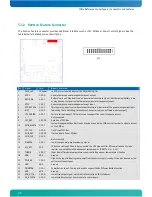
The Kontron Feature connector provides additional interfaces such as I2C, SMBus or Power Control Signals. See the
table below for detailed pin-out description.
Pin
Signal
Level
Signal Description
1
PWR_+5V
5V power
+5V UL-protected with inductor (600R@100MHz, 1A)
2
GPO2
3.3V-O
General-purpose power management event output
3
BATLOW#
3.3V-I
Battery low input. May be driven low by external circuitry to signal that the system battery is low,
or may be used to signal some other external power management event.
4
GPI2
3.3V-I
General-purpose power management event input
5
SYS_RESET#
3.3V-I
This input may be driven low by external circuitry in order to reset the power management logic
6
WDT
3.3V-O
Indicating that a Watchdog Timeout Event has occurred (non buffered module output)
7
LPC_SERIRQ
3.3V-I
Serial interrupt request. This pin is used to support the serial interrupt protocol.
8
-
-
Not connected
9
I2C_DAT
3.3V-IO
Data line of I2C-Bus
10
SMB_ALERT# 3.3V-I
System Management Bus Alert input. May be driven low by SMB devices in order to signal an event
on the SM Bus
11
I2C_CLK
3.3V-O
Clock line of I2C-Bus
12
SMB_DAT
3.3V-IO
Clock and data line of SM-Bus.
13
SMB_CLK
3.3V-O
14
-
-
Not connected
15
WAKE1#
3.3V-I
Low driven general purpose wake-up signal
16
VCC_RTC
3V-I
3V backup cell input. Should be connected to a 3V backup cell for RTC operation and storage
register non-volatility in the absence of system power. (VBATT = 2.4 – 3.3V)
17
THRM#
3.3V-I
Input from off-module temperature sensor indicating an over temperature situation
18
GND
GND
Ground
19
PWR_OK
3.3V-I
High active input indicating that power from the power supply is ready. It can also be used as low
active reset input signal.
20
GND
GND
Ground
21
PWRBTN#
3.3V-I
Power Button Input. This input is used to support the ACPI Power Button function.
22
GND
GND
Ground
23
ATA_ACT#
3.3V-O
Low active output signal, which indicates activity on IDE interfaces.
24
CB_RESET#
3.3V-O
Low active Reset output from module to carrier board
Summary of Contents for COMe Ref.Carrier T6
Page 1: ...If it s embedded it s Kontron COMe Reference Carrier Type 6 Document Revision 1 0 ...
Page 8: ...COMe Reference Carrier Type 6 Specification 5 3 2 Block Diagram ...
Page 13: ...COMe Reference Carrier Type 6 Connector Layout 10 4 2 Connector Locations ...
Page 14: ...COMe Reference Carrier Type 6 Connector Layout 11 ...


