background image


22 


2.


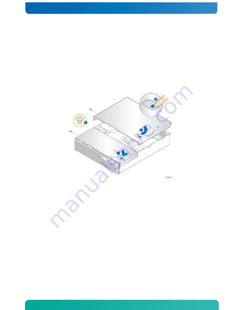
While holding the blue button at the top right of the front cover (Figure 10, 
“B”), slide the cover forward until it stops. 

3.


Lift the cover straight up to remove it from the chassis. 

Removing the Back Cover 

1.


Remove the shipping screw on the left side edge of the cover, if it is still 
attached, and save it for future use. (Figure 10, “A”) 

2.


While holding the blue button at the top right of the rear cover (Figure 10, 
“B”), slide the cover backwards until it stops and the edge clears the lock 
bracket on the rear panel of the chassis. 

3.


Lift the cover straight up to remove it from the chassis. 

Figure 10. Removing the Covers 


Re-installing the Chassis Covers 

When you are finished working inside the chassis, you must put the cover(s) back on 
before turning the server back on. This step is required to ensure proper cooling. 

If you are reinstalling both covers, start with the back cover and then install the 
front cover. 

Re-Installing the Back Cover 

1.


Starting from the rear of the chassis, align the tab on the rear left edge of 
the back cover with the lock bracket on the outside of the rear panel and place 
the cover down over the chassis with the side edges outside the chassis walls. 

2.


Slide the cover forward until it clicks into place. 

3.


Install the shipping screw if tooled entry is required or if the unit will be 
shipped. 

4.


Reconnect all peripheral devices and the power cord(s). 

Re-Installing the Front Cover 

1.


Place the front cover over the chassis with the side edges of the cover outside 
the chassis walls. 

Summary of Contents for CG2100

Page 1: ...Kontron CG2100 Carrier Grade Server Document Revision 1 2 ...

Page 2: ...r Board Baseboard 16 2 9 Riser Card Assembly 17 2 10 Ethernet NIC Ports 18 2 11 Remote Management Module 3 18 2 12 Power Supply Subsystem 18 2 13 System Cooling 19 2 14 Processors and Memory DIMMs 19 Processors 20 Memory 20 3 Standard Component Installations and Upgrades 21 3 1 Before You Begin 21 Tools and Supplies Needed 21 System References 21 3 2 General Installation Procedures 21 Removing the...

Page 3: ...stalling or Replacing Hard Disk Drives 40 Removing an HDD Carrier from the Chassis 40 Installing a Hard Drive in a Carrier 41 4 3 Installing a SAS SATA Control Module 42 4 4 Installing a Hardware RAID Module 45 4 5 Installing a RAID Intelligent Battery Backup Unit IBBU 46 4 6 Adding a Second Power Supply Module 47 4 7 Installing a PCI Riser Card 48 4 8 Installing PCI Add in Cards 49 4 9 Installing...

Page 4: ...arms Module TAM 68 Removing the Old Telco Alarms Module 68 Installing the New Telco Alarms Module 69 5 7 Replacing the Power Distribution Board 69 Removing the Old Power Distribution Board 70 Installing the New Power Distribution Board 71 5 8 Replacing the T5520UR Server Board 71 Removing the Old Server Board from the Chassis 72 Installing the New Server Board 73 5 9 Replacing the SAS SATA Backpla...

Page 5: ... Stopped Working When an Add in Adapter was Installed 86 The Add in Adapter Stopped Working without Apparent Cause 86 System Boots When Installing a PCI Card 87 Problems with Newly Installed Application Software 87 Problems with Application Software that Ran Correctly Earlier 87 Devices are not Recognized under Device Manager Windows OS 87 Hard Drive s are not Recognized 88 7 5 LED Information 88 ...

Page 6: ...iance 105 Certifications Registrations Declarations 105 10 2 Electromagnetic Compatibility Notices 106 FCC USA 106 Industry Canada ICES 003 106 Europe CE Declaration of Conformity 106 VCCI Japan 107 BSMI Taiwan 107 Regulated Specified Components 107 11 Appendix C Getting Help 108 11 1 World Wide Web 108 11 2 Telephone 108 11 3 Email 108 ...

Page 7: ...components such as PCI add in cards personality modules hardware RAID5 components and an SD flash module Use this chapter for step by step instructions and diagrams for installing components Chapter 5 Server Component Replacements provides instructions for replacing components such boards and fans Use this chapter for step by step instructions and diagrams for replacing components Chapter 6 Server...

Page 8: ...ntel Xeon processor 5600 series and appropriate heat sink s RDIMM UDIMM DDR3 memory SAS or SATA hard disk drives system maximum six HDDs Hard disk drive carriers SAS SATA control module for basic hard drive support Hardware RAID 5 and 6 kit Optional battery backup IBBU for hardware RAID SMART embedded USB solid state drive for use on front panel board and baseboard SD flash module for up to two SD...

Page 9: ...e Technical Product Specifications TPSs for the system and the server board The TPS documents are located on the Kontron support website at http us kontron com support The system TPS provides in depth technical information about the server The server board TPS provides in depth technical information about the server board including BIOS settings and chipset information ...

Page 10: ...ne front and one rear with same physical connection that allows front or rear use only Two RJ45 10 100 1000 Mbps network connections rear Four USB 2 0 connectors rear One USB 2 0 connector front Internal connections Two low profile USB 2x5 pin headers for low profile USB solid state drives such as the SMART Embedded USB Solid State Drive One header is located on the front panel board and the other...

Page 11: ...nt Panel Buttons Power on off System reset Chassis ID NMI Front Panel LEDs Power status Chassis identification System status Fan status HDD activity fault NIC activity Alarms critical major minor power Power Supply Up to two 600W power supply modules AC or DC Fans Four redundant hot swappable CPU memory area cooling fans Two redundant hot swappable PCI area cooling fans Two optional redundant powe...

Page 12: ...11 Figure 2 CG2100 Carrier Grade Server Components ...

Page 13: ...board and SAS SATA module location O Two CPUs CPU 1 shown F Power distribution board PDB P DDR3 memory DIMM sockets CPU 2 DIMM slots shown G SAS SATA control module or SAS SATA RAID module Q System fans H Power supply cage for two power supply modules R Front panel board with optional SD flash module and TAM module I Redundant hot swappable power supply modules S LED switch board and telco alarm L...

Page 14: ... Front View Bezel Removed Item Description Item Description A ESD ground strap attachment G Hard drive bay 0 B Hard drive bay 5 H Front panel control buttons status indicator and telco alarm LEDs C Hard drive bay 4 I RJ45 serial port COM2 serial B D Hard drive bay 3 J USB port E Hard drive bay 2 K SD flash module 0 optional F Hard drive bay 1 L SD flash module 1 optional Figure 5 shows the CG2100 ...

Page 15: ...g Yellow is the default color 2 3 CG2100 Server Back Panel Figure 6 shows the back panel of the CG2100 server Figure 6 CG2100 Server Rear View Ite m Description Ite m Description A Two low profile PCIe add in cards or filler panels H GbE NIC 2 connector4 B Three full length PCIe add in cards or filler panels I GbE NIC 1 connector4 C Power supply 2 optional filler panel shown J 1 USB 2 and 3 3 on t...

Page 16: ...uitry for driving the NIC activity LED the system status LED the power LED and the disk activity LED all located on the LED switch board Control circuitry for driving a composite fan fault LED to the LED switch board On board LED indicating USB flash drive activity System power state and status indicators power reset and NMI switches Control circuitry for driving telco alarm activity LEDs to the L...

Page 17: ...flash module that supports two SD cards For a list of validated SD cards to use with this module see the Tested Hardware and Operating System List THOL on the Kontron website at http us kontron com support search for CG2100 click on Product Downloads and then Compatibility Matrix 2 8 Server Board Baseboard The CG2100 server uses the Intel server board T5520UR for the baseboard The processors and m...

Page 18: ...nnector L CPU2 Y Internal USB header M Fan header 2 9 Riser Card Assembly The CG2100 server has a PCI riser assembly that supports the installation of both PCI X and PCI Express add in cards There are three riser card options that can each use the super slot on the T5520UR server board the baseboard Once PCI add in cards are installed and the riser card assembly is remounted in the chassis the car...

Page 19: ... Module 3 RMM3 is implemented on the iBMC on the server board To use this feature a separately orderable GCM4 NIC module must be installed 2 12 Power Supply Subsystem The power supply subsystem consists of up to two AC or DC power supply modules two needed for redundancy and a power distribution board PDB One power supply module is included with the server with a filler panel in the second power s...

Page 20: ...lso cool the hard disk drives The air flow is adequate even with a single power supply module installed as long as the filler panel is installed in the unused power supply slot Figure 9 CG2100 Server Cooling Areas The three zone cooling subsystem is sized to provide cooling for Up to two server board processors Up to 96 GB of DDR3 memory Up to six SAS SATA hard disk drives Up to five PCI add in ca...

Page 21: ...or supports DDR3 800 DDR3 1066 and DDR3 1333 memory technologies The memory controller supports both registered DIMMs RDIMMs and unbuffered DIMMs UDIMMs RDIMMs must be ECC only while UDIMMs can be ECC or non ECC RDIMMs and UDIMMs cannot be mixed ECC and non ECC UDIMMs can be mixed but the presence of a single non ECC UDIMM disables ECC functionality The T5520UR server board supports six DDR3 memor...

Page 22: ...edures The following sections present general installation and removal procedures that are required before removing or installing internal components that are not hot swappable from the front or rear panels Removing the Chassis Covers The CG2100 server must be operated with the top covers in place to ensure proper cooling You will need to remove one or both top covers to add or replace components ...

Page 23: ...n you are finished working inside the chassis you must put the cover s back on before turning the server back on This step is required to ensure proper cooling If you are reinstalling both covers start with the back cover and then install the front cover Re Installing the Back Cover 1 Starting from the rear of the chassis align the tab on the rear left edge of the back cover with the lock bracket ...

Page 24: ...aptive bezel retention screw on the right side of the bezel A 2 Rotate the bezel to the left to free it from the pins on the front panel as shown in Figure 11 B and remove it Figure 11 Removing the Front Bezel Re Installing the Front Bezel 1 Insert the tabs on the left side of the bezel into the slots on the front panel of the chassis 2 Move the bezel toward the right of the front panel and align ...

Page 25: ...ge Figure 12 Riser Card Assembly Retention Screw Re Installing the Riser Card Assembly To re install the riser card assembly 1 Position the riser front tab guide hole over the guide pin on the server board See Figure 13 C 2 Make sure the forks on the back of the assembly rest securely on the guide pins on the rear of the chassis B 3 Using the blue touch points on the top of the assembly A press do...

Page 26: ...he back cover To remove the processor air duct 1 Power down the server and remove all peripheral devices and the power cord s 2 Remove the back chassis cover For instructions see Removing the Chassis Covers 3 Remove the riser card assembly For instructions see Removing the Riser Card Assembly 4 Slide the air duct back to free it from the fan bracket and towards the center of the chassis to free it...

Page 27: ...le components that must be installed for your server to operate It also covers replacing these components and where relevant such as with memory DIMMs how to configure them You install your separately orderable DIMMs and processors on the Intel Server Board T5520UR which is the baseboard for this server NOTE Be sure to read the following detailed information about the configuration rules and memor...

Page 28: ... DDR3 800 DDR3 1066 and DDR3 1333 memory technologies Memory modules of mixed speed are supported by automatic selection of the highest common frequency of all memory modules Publishing System Memory The BIOS displays the Total Memory of the system on the diagnostic screen at the end of POST if Display Logo is disabled in the BIOS setup This is the total size of memory discovered by the BIOS durin...

Page 29: ...ndent mode One exception to this rule is when all DIMM slots for a socket are empty for example when only sockets A1 B1 C1 are populated mirroring is possible on the platform The memory slots of DDR3 channels from the Intel Xeon Processor 5600 Series should be populated in a farthest first fashion This holds true even in the Channel Independent mode This means for example that A2 cannot be populat...

Page 30: ...first two adjacent channels to be active Socket configuration Mirroring requires that both socket 1 and socket 2 DIMM population meets the requirements for mirroring mode The platform BIOS configures the system in mirroring mode only if both nodes qualify The only exception to this rule is when all socket 2 DIMM slots are empty Because of these requirements the minimal DIMM population is A1 B1 In ...

Page 31: ...ets are populated but channel A through channel C are empty the platform can still function with remote memory in channel D through channel F However platform performance suffers latency with remote memory The memory operational mode is configurable at the channel level Two modes are supported Independent Channel and Mirrored Channel The memory slots of each DDR3 channel from the Intel Xeon Proces...

Page 32: ...DIMMs on adjacent channels of a socket are not identical the BIOS configures both the processor sockets to default to the Independent Channel mode If DIMM D1 and DIMM E1 are not identical then the system switches to the Independent Channel Mode Installing Memory DIMMs NOTE To reduce the risk of electrostatic discharge ESD damage to the processor or the DIMM be sure to follow these procedures 1 Tou...

Page 33: ...low these steps 1 Remove the back chassis cover For instructions see Removing the Back Cover 2 Remove the riser card assembly so the processor air duct can be removed For instructions see Removing the Riser Card Assembly 3 Remove the processor air duct For instructions see Removing the Processor Air Duct 4 Open the DIMM slot levers for the DIMM you want to remove 5 Using both hands hold the DIMM b...

Page 34: ...cessor by doing the following Touch the metal chassis before touching the processor or server board Keep part of your body in contact with the metal chassis to dissipate the static charge while handling the processor Avoid moving around unnecessarily Use a ground strap attached to the front panel with the bezel removed When opening a socket do not touch the gold socket wires When unpacking a proce...

Page 35: ...load plate all the way Figure 19 A Figure 19 Opening the Load Plate 6 Remove the processor Installing a New Processor NOTE Follow the ESD precautions covered in ESD and Processor Handling Precautions To install a processor follow these instructions 1 Take the processor out of its packaging and remove the protective shipping cover Figure 20 A Figure 20 Removing the Shipping Cover ...

Page 36: ...e processor cutouts match the socket notches 4 Figure 22 A 5 Gently place the processor in the socket B Figure 22 Installing the Processor in the Processor Socket 6 Close the load plate 7 Figure 23 A Figure 23 Closing the Processor Load Plate and Socket Lever 8 Close the socket lever and ensure that the load plate tab engages under the socket lever when fully closed B and C Inserting the Heat Sink...

Page 37: ... with the jumpers defined in this section you must first power down the chassis remove the back cover remove the riser card assembly and remove the processor air duct as described in Section 3 2 General Installation Procedures The other components on the server board can remain in place The server board has several 3 pin jumper blocks that can be used to configure protect or recover specific featu...

Page 38: ...er passwords are cleared within 5 10 seconds after the system is powered on These pins should not be jumpered for normal operation J1D4 BIOS Recover 1 2 These pins should have a jumper in place for normal system operation Default 2 3 Since the main system BIOS will not boot with these pins jumpered the system can only boot from EFI bootable recovery media with the recovery BIOS image J1H2 BMC Forc...

Page 39: ... product pay close attention to the safety instructions provided in this manual See Appendix A Safety Information Warning Electrostatic discharge ESD and ESD protection ESD can damage disk drives boards and other parts We recommend that you perform all procedures in this chapter only at an ESD workstation If one is not available provide some ESD protection by wearing an antistatic wrist strap atta...

Page 40: ...9 Figure 25 Cable Routing Table 5 System Cables Cable Number and Name End 1 Connection End 2 Connection End 3 Connection 1 Power distribution Power distribution board SAS SATA backplane Front panel board ...

Page 41: ...d disk drives the unused drive bays must contain the empty carriers that ship with the server to maintain proper cooling The CG2100 server does not support all SAS SATA hard disk drives To see a list of validated manufacturers and drive models refer to the THOL The latest version of the THOL is located on the Kontron support website at http us kontron com support Search for CG2100 click on Product...

Page 42: ...rive 2 Lift the drive out of the carrier B Figure 27 Removing a Hard Drive 3 Install the new drive in the drive carrier Figure 28 A and secure the drive with the four screws that come with the carrier B Figure 28 Installing a Hard Drive 4 With the drive carrier locking lever fully open push the hard drive carrier into the drive bay in the chassis until it stops Figure 29 A 5 Press the locking leve...

Page 43: ...ridge board The SAS SATA control module is located in the front left of the chassis between the power supply system and the SAS SATA backplane board The module s gold edge connector C mates with the SAS SATA backplane board Figure 30 SAS SATA Control Module Before you can install the SAS SATA control module you need to slide the power supply module s out a little for easy access to the module brac...

Page 44: ...ane board and insert the SAS SATA control module card edge into the edge connector on the backplane board Figure 32 A and B Figure 32 Installing the SAS SATA Control Module 6 Fasten the bracket to the SAS SATA backplane hold down plate with one screw C 7 Attach the flex circuit cable Figure 33 A to the connector on the SAS SATA control module B ...

Page 45: ... protective cover Figure 34 A over the flex cable and snap it into the grooves on the side wall B and C Figure 34 Installing the Flex Circuit Cable Cover 9 Place the metal retention clip over the flex circuit cable connector Figure 35 A and secure it with the screw B ...

Page 46: ...e RAID module which provides SAS SATA RAID functionality for the server using an LSI Logic LSISAS1078 hardware RAID controller B The module s interface to the baseboard is through a PCI Express bus flex circuit cable A to the bridge board The SAS SATA hardware RAID module is located in the front left of the chassis between the power supply system and the SAS SATA backplane board The module s gold ...

Page 47: ...igure 34 A over the flex cable and snap it into the grooves on the side wall B and C 10 Place the metal retention clip over the flex circuit cable connector See Figure 35 A Secure it with the screw B 11 If this is the last task you are performing inside the chassis slide the power supply modules back into place and replace the top front cover 4 5 Installing a RAID Intelligent Battery Backup Unit I...

Page 48: ...re 40 A 2 Press and hold the green safety lock downward and using the handle slide the power supply into the slot until it latches into place B and C 3 If you are installing a DC power supply there are two threaded studs for chassis enclosure grounding D A 90 standard barrel two hole compression terminal lug with 5 8 inch pitch suitable for a 14 10 AWG conductor must be used for proper safety grou...

Page 49: ...and two low profile PCIe x4 slots 2U PCIe passive riser three full height full length PCIe x8 slots In this section the riser card example is a full height full length riser as shown in Figure 41 Figure 41 Riser Card Assembly with 2U PCIe PCI X Butterfly Riser CAUTION When handling the riser card observe normal safety and ESD precautions See Appendix A Safety Information for more information To in...

Page 50: ...e riser card assembly upside down so it is resting on the top of the sheet metal cage 2 Figure 42 A Save the screw to use with the new add in card 3 If you are replacing a PCI card in a slot remove the rear retention screw that fastens the add in card to the riser card B and remove the card from the riser card socket 4 For a full height add in card remove the front retention clip by loosening the ...

Page 51: ...ly in Section 3 2 3 Remove the processor air duct For instructions see Removing the Processor Air Duct in Section 3 2 4 For the 10 GbE I O module both filler panels must be removed to support all the ports Squeeze the sides of the module filler panel to remove it from the rear panel of the chassis Figure 43 A Figure 43 Removing a Personality Module Filler Panel 5 Locate the three plastic standoffs...

Page 52: ...on cable to connect the module to the server board To install the GCM NIC module you must first remove the back chassis cover the riser card assembly and the processor air duct 1 Remove the back chassis cover For instructions see Removing the Back Cover in Section 3 2 2 Remove the riser card assembly so the processor air duct can be removed For instructions see Removing the Riser Card Assembly in ...

Page 53: ...rear panel over the NIC C Figure 46 Installing the GCM NIC Module 8 If this is the last task you are performing replace the processor air duct the riser card assembly and the back chassis cover Reconnect all the external devices and plug in the power cord s 4 11 Installing an SD Flash Module The CG2100 server SD flash module supports the use of two SD flash memory card The SD flash module package ...

Page 54: ...n the black protective cover over the front panel board 4 Remove the filler panel from the front on the server chassis Figure 47 A and save the two screws for use with the SD flash module bracket Slide the filler panel out of the chassis through the front B Figure 47 Removing the SD Flash Module Filler Panel 5 Line up the SD flash module with the stand offs on the bracket and secure the module wit...

Page 55: ...USB Cable 7 Insert the SD flash module bracket from the front of the chassis Figure 50 A 8 Fasten the bracket with the two screws that were used to attach the filler panel originally B Figure 50 Attaching the SD Module Bracket to the Front Panel 9 Secure the SD flash module to the FP board with the screw provided C ...

Page 56: ...guration data There are two places where a solid state drive can be installed on the CG2100 server on the front panel board and on the server board Installing a Solid State Drive on the Front Panel Board 1 Remove the front chassis cover For instructions see Removing the Front Cover in Section 3 2 2 Unfasten the black protective cover over the front panel board 3 Insert the drive module onto the fr...

Page 57: ...ssor Air Duct in Section 3 2 4 Locate the white plastic standoff on the server board Figure 52 A 5 Insert the drive module onto the server board by connecting the drive module to the standoff on the server board and the USB connector on the drive module onto the server board USB header B 6 If this is the last task you are performing re install the processor air duct the riser card assembly and the...

Page 58: ...t also consider the weight of any other device installed in the rack Mains power disconnect The power cord s is considered the mains disconnect for the server and must be readily accessible when installed If the individual server power cord s will not be readily accessible for disconnection then you are responsible for installing a power disconnect for the entire rack unit This main disconnect mus...

Page 59: ...circuit with more than 20 amperes of protection you must provide supplemental protection for the server The overall current rating of a server configured with two power supplies is less than 4 amperes CAUTION Temperature The operating temperature of the server when installed in an equipment rack must not go below 5 C 41 F or rise above 40 C 104 F Extreme fluctuations in temperature can cause a var...

Page 60: ...d 2 Phillips bits Personal grounding device such as an anti static wrist strap and a grounded conductive pad System References All references to left right front top and bottom assume that you are facing the front of the server as it would be positioned for normal operation Cable Routing Reference It is important for cables to be connected correctly See Figure 25 and Table 5 for cable routing and ...

Page 61: ...the header on the side of the metal enclosure 5 If this is the last task you are performing close the front chassis cover Replacing 60mm PCI Fans The two 60mm fan assemblies are located next to the HDD bay enclosure See Figure 2 Q These fans are in front of the riser card assembly and provide cooling for the PCI cards in this assembly 1 Remove the front chassis cover For instructions see Removing ...

Page 62: ...he power cord s from the system and wall outlet When handling the bridge board observe the normal safety and ESD precautions See Appendix A Safety Information for more information For the location of the cables connected to the bridge board see Figure 7 and Table 5 Removing the Bridge Board To remove the bridge board from the chassis 1 Remove both of the chassis covers For instructions see Removin...

Page 63: ...ure 56 A and B Figure 56 Disconnecting the Flex Circuit Cable Removing the Guide Bracket and Releasing the Bridge Board 1 Disconnect the serial port cable from the bridge board 2 Remove the black plastic riser card assembly baffle bridge board guide bracket by loosening the two screws that secure it to the chassis base Figure 57 A and B Figure 57 Removing the Guide Bracket from the Bridge Board ...

Page 64: ...rd Figure 58 Removing the Bridge Board from the Chassis Re Installing the Bridge Board To replace the bridge board back into the chassis 1 Align the bridge board edge connectors with the latch clip headers on the FP board and the baseboard Make sure that the keying slot in the rear bridge board edge connector aligns with the key in the baseboard header 2 Press down to make a firm connection at bot...

Page 65: ...front panel board provides the interface to the controls at the front of the server the power interconnect for the server board the USB and serial port B interface The FP board also houses the LED switch board that controls the front panel LEDs and the telco alarm manager as well as the optional USB SSD and SD flash modules To replace the FP board you must first remove the following components The...

Page 66: ...e riser card assembly For instructions see Removing the Riser Card Assembly in Section 3 2 3 Remove the processor air duct For instructions see Removing the Processor Air Duct in Section 3 2 4 Unfasten the black protective cover on top of the FP board 5 Disconnect all of the cables connected to the FP board See Figure 7 and Table 4 for the cable routing For the location of each connector see Figur...

Page 67: ...panel of the chassis and the two keyhole slots fit over the standoffs on the bottom of the chassis Figure 61 A 3 Tighten the screw at the rear of the board to secure it to the chassis base B Figure 61 Installing the New FP Board 4 Reconnect all of the cables on the FP board For locations of each header on the board see Figure 59 4 1 Reconnect the front panel power cable that comes from the SAS SAT...

Page 68: ...ct the LED switch board ribbon cable and then unfasten the screw on the top right side of the LED switch board If you do not have enough room to access this screw you will have to remove or at least slide back the FP board For instructions see Removing the Old Front Panel Board in Section 5 4 5 The LED switch board is also attached to the front of the chassis by two standoffs Once the retaining sc...

Page 69: ...front panel board or at least loosen it and slide it back in order to access the TAM board CAUTION Before replacing any of the boards on the CG2100 server you must first take the server out of service turn off all peripheral devices connected to the server turn off the server by pressing the power button and unplug the power cord s from the system and wall outlet Removing the Old Telco Alarms Modu...

Page 70: ...ctions see Installing the New Front Panel Board in Section 5 4 4 Connect the alarms cable from the FP board to the TAM board Figure 63 A 5 Connect the alarms cable from the rear of the chassis to the TAM board B 6 Re fasten the black protective cover over the FP board 7 If this is the last task you are performing inside the server chassis replace the front chassis cover reconnect the power cord s ...

Page 71: ...n Section 3 2 4 Remove the black plastic riser card assembly bridge board guide bracket by loosening the two screws that secure it to the chassis base See Figure 57 for the location of this bracket and the screws that attach it 5 Slide the power supply module s out a few inches to disengage it from the PDB 6 Remove the SAS SATA control module or SAS SATA hardware RAID module if installed See Secti...

Page 72: ... a SAS SATA Control Module or Section 4 4 Installing a Hardware RAID Module for help with how to fasten the module reconnect the flex cable and replace the sheet metal cover 7 Replace the power supply module s so they are mated with the PDB 8 Replace the black plastic PCI air baffle bridge board guide bracket with the two screws that secure it to the chassis base See Figure 57 for the location of ...

Page 73: ...ion 3 2 4 Remove the processor air duct For instructions see Removing the Processor Air Duct in Section 3 2 5 Remove the black plastic riser card assembly bridge board guide bracket by loosening the two screws that secure it to the chassis base See Figure 57 for the location of this bracket and the screws that attach it 6 Disconnect all the cables attached to the server board or routed over it a T...

Page 74: ...led and you are re using components from the old server board install components as follows To install memory DIMMs see Installing Memory DIMMs in Section 3 3 To install heat sink s and processor s see Installing a New Processor in Section 3 3 4 Re install the personality module s if used For information about how these cards are installed see Section 4 9 Installing a Personality Module 5 Re insta...

Page 75: ...backplane board CAUTION Before replacing any of the boards on the CG2100 server you must first take the server out of service turn off all peripheral devices connected to the server turn off the server by pressing the power button and unplug the power cord s from the system and wall outlet When handling the SAS SATA backplane board observe the normal safety and ESD precautions See Appendix A Safet...

Page 76: ...to the drive bay assembly Figure 67 A Slide the cover plate towards the side chassis wall B to release the four tabs C Lift the cover plate off of the HDD bay assembly D Figure 67 Removing the HDD Bay Assembly Cover Plate 7 Lift the backplane board part way out Figure 68 A Disconnect the power cable B from the front of the backplane board C ...

Page 77: ... the board fits securely between the edge of the HDD bay assembly and the guide pins on the HDD bay assembly Figure 69 A and B Figure 69 Installing the Backplane Board 2 Connect the power cable into the front of the backplane board leaving the board only partially inserted C 3 Make sure the metal clips on the bottom of the backplane board line up with the HDD bay assemble flange Figure 70 A Press ...

Page 78: ... 5 Re install the SAS SATA control module or SAS SATA hardware RAID module if used and the sheet metal bracket For instructions see either Section 4 3 Installing a SAS SATA Control Module or Section 4 4 Installing a Hardware RAID Module 6 Re attach the front panel bezel For instructions see Re Installing the Front Bezel in Section 3 2 7 If this is the last task you are performing inside the server...

Page 79: ...pt Press F2 to enter SETUP Pressing F2 when prompted invokes BIOS setup The BIOS continues to perform necessary initialization procedures and then displays the BIOS Setup menus If You Cannot Access Setup If you are not able to access BIOS Setup you might need to restore the BIOS options to their factory settings For instructions on restoring factory defaults see Section 6 3 Restoring Factory Defau...

Page 80: ...e is a submenu or to display a pick list if a selected feature has a value field or to select a sub field for multi valued features like time and date If a pick list is displayed the Enter key undoes the pick list and allows another selection in the parent menu Esc Exit The ESC key provides a mechanism for backing out of any field This key undoes pressing the Enter key When the ESC key is pressed ...

Page 81: ... to service See Section 1 4 Additional Information and Software for additional information Obtaining the Upgrade Download the BIOS image file to a temporary folder on your hard drive See Section 1 4 Additional Information and Software for more information Note Review the instructions and release notes that are provided in the readme file distributed with the BIOS image file before attempting a BIO...

Page 82: ...2 for instructions 7 Power up the system 6 4 Clearing the Password If the user or administrator password s is lost or forgotten moving the password clear jumper J1E8 into the clear position clears both passwords The password clear jumper must be restored to its original position before a new password s can be set The password clear jumper is shown in Figure 24 1 Power down the system and disconnec...

Page 83: ...r stating that the BMC is still in update mode Use the following procedure to get out of Update mode 1 Power down the server and unplug the power cord s 2 Open the server chassis See Removing the Chassis Covers in Section 3 2 for instructions 3 Locate jumper block J1H2 and move the jumper to the Enable position pins 2 3 4 Close the server chassis See Re installing the Chassis Covers in Section 3 2...

Page 84: ...ng system Ctrl Alt Del Clear system memory restart POST and reload the operating system Reset button Cold boot reset Turn the system power off and then on This clears system memory restarts POST reloads the operating system and halts power to all peripherals Power on off 7 2 Problems Following Initial System Installation Problems that occur at initial system startup are usually caused by an incorr...

Page 85: ... its source CAUTION Turn off devices before disconnecting cables Before disconnecting any peripheral cables from the system turn off the system and any external peripheral devices Failure to do so can cause permanent damage to the system and or the peripheral devices 1 Turn off the system and all external peripheral devices Disconnect each of devices from the system except for the keyboard and the...

Page 86: ...o Characters Appear on Screen Check the following 1 Is the keyboard functioning Test it by turning the Num Lock function on and off to make sure the Num Lock light is functioning 1 Is the video monitor plugged in and turned on If you are using a switch box is it switched to the correct system 1 Are the brightness and contrast controls on the video monitor properly adjusted 1 Is the video monitor s...

Page 87: ...rrect and the current drivers Go to http us kontron com products systems and platforms communication rackmount se rvers carrier grade servers cg2100 carrier grade server html for a link to the drivers 1 Make sure the driver is loaded and the protocols are bound 1 Make sure the hub port is configured for the same duplex mode as the network controller 1 Make sure the correct networking software is i...

Page 88: ...hat occur after the system hardware and software have been running correctly sometimes indicate equipment failure However they can also be caused by file corruption or changes to the software configuration Check the following 1 Uninstall and reinstall the software Make sure all necessary files are installed 1 If the problems are intermittent there may be a loose cable dirt in the keyboard if keybo...

Page 89: ...server html for a link to the list tested drives 1 Make sure you have not exceeded the power budget for the server Go to http us kontron com products systems and platforms communication rackmount se rvers carrier grade servers cg2100 carrier grade server html for a link to software to check your power budget 7 5 LED Information The Intel Server Board T5520UR includes LEDs that can aid in troublesh...

Page 90: ...Green blinking activity no action required Amber drive fault Off no access no HDD fault See CG2100 Technical Product Specification for more information about hard drive LED operation Memory fault 1 12 Identify failing memory module DIMM end rear of server Amber On fault Diagnostic LEDs 1 8 LSB bit1 bit2 MSB Display port 80 POST codes Center back edge of server board Each LED can be off green amber...

Page 91: ...ted by BIOS beep codes Table 8 POST Error Beep Codes Number of Beeps Reason for the Beeps and Action to Take 1 2 or 3 Memory error Reseat the memory or replace the DIMMs with known good modules 4 7 or 9 11 Fatal error indicating a possible serious system problem Remove all add in cards and re start the system If the error still occurs contact your system manufacturer If the beep codes are not gene...

Page 92: ... processor 1 5 2 1 No processor is installed or the CPU 1 socket is empty Reseat or replace the failed processor 1 5 2 3 Processor configuration error or CPU 1 socket is empty Reseat or replace the failed processor In a two processor system make sure the processors are identical 1 5 2 4 Front side bus select configuration error 1 5 4 2 DC power unexpectedly lost 1 5 4 3 Chipset control failure 1 5...

Page 93: ...repair of products is free of charge as long as warranty conditions are observed The warranty does not apply to defects resulting from improper or inadequate maintenance or handling by the buyer unauthorized modification or misuse operation outside of the product s environmental specifications or improper installation or maintenance Kontron will not be responsible for any defects or damages to oth...

Page 94: ...e equipment rack must be anchored to an unmovable support to prevent it from falling over when one or more servers are extended in front of the rack on slides You must also consider the weight of any other device installed in the rack A crush hazard exists should the rack tilt forward which could cause serious injury WARNING The intra building port s of the equipment or subassembly is suitable for...

Page 95: ...ted Access Location in accordance with articles 110 26 and 110 27 of the National Electric Code ANSI NFPA 70 The DC source must be electrically isolated from any hazardous AC source by double or reinforced insulation The DC source must be capable of providing up to 300 watts of continuous power per feed pair Mains DC power disconnect You are responsible for installing a properly rated DC power dis...

Page 96: ...he exact type required A product with more than one power supply will have a separate AC power cord for each supply The power button on the system does not turn off system AC power To remove AC power from the system you must unplug each AC power cord from the wall outlet or power supply The power cord s is considered the disconnect device to the main AC power The socket outlet that the system plug...

Page 97: ...e made with care Consider wearing protective gloves Danger of explosion if the battery is incorrectly replaced Replace only with the same or equivalent type recommended by the equipment manufacturer Dispose of used batteries according to manufacturer s instructions The system is designed to operate in a typical office environment Choose a site that is Clean and free of airborne particles other tha...

Page 98: ...hres Systems aus der Steckdose 4 Auf der Rückseite des Systems beschriften und ziehen Sie alle Anschlußkabel von den I O Anschlüssen oder Ports ab 5 Tragen Sie ein geerdetes Antistatik Gelenkband um elektrostatische Ladungen ESD über blanke Metallstellen bei der Handhabung der Komponenten zu vermeiden 6 Schalten Sie das System niemals ohne ordnungsgemäß montiertes Gehäuse ein Nachdem Sie die oben ...

Page 99: ...Das System wurde für den Betrieb in einer normalen Büroumgebung entwickelt Der Standort sollte sauber und staubfrei sein Hausstaub ausgenommen gut gelüftet und keinen Heizquellen ausgesetzt sein einschließlich direkter Sonneneinstrahlung keinen Erschütterungen ausgesetzt sein keine starken von elektrischen Geräten erzeugten elektromagnetischen Felder aufweisen in Regionen in denen elektrische Stür...

Page 100: ...le système 5 Pour prévenir les décharges électrostatiques lorsque vous touchez aux composants portez une bande antistatique pour poignet et reliez la à la masse du système toute surface métallique non peinte du boîtier 6 Ne faites pas fonctionner le système tandis que le boîtier est ouvert Une fois TOUTES les étapes précédentes accomplies vous pouvez retirer les panneaux du système Procédez comme ...

Page 101: ...a poussière normale Bien aéré et loin des sources de chaleur y compris du soleil direct A l abri des chocs et des sources de vibrations Isolé de forts champs électromagnétiques géenérés par des appareils électriques Dans les régions sujettes aux orages magnétiques il est recomandé de brancher votre système à un supresseur de surtension et de débrancher toutes les lignes de télécommunications de vo...

Page 102: ...ante protegerse contra la descarga electrostática ESD Puede hacerlo si utiliza una muñequera antiestática sujetada a la toma de tierra del chasis o a cualquier tipo de superficie de metal sin pintar 6 No ponga en marcha el sistema si se han extraído las tapas del chasis Después de completar las seis instrucciones de SEGURIDAD mencionadas ya puede extraer las tapas del sistema Para ello 1 Desbloque...

Page 103: ...alejado de fuentes de calor incluida la luz solar directa Alejado de fuentes de vibración Aislado de campos electromagnéticos fuertes producidos por dispositivos eléctricos En regiones con frecuentes tormentas eléctricas se recomienda conectar su sistema a un eliminador de sobrevoltage y desconectar el módem de las líneas de telecomunicación durante las tormentas Provisto de una toma de tierra cor...

Page 104: ...ta 6 Non far operare il sistema quando il telaio è senza le coperture Dopo aver seguito i sei passi di SICUREZZA sopracitati togliere le coperture del telaio del sistema come seque 1 Aprire e rimuovere il lucchetto dal retro del sistema qualora ve ne fosse uno installato 2 Togliere e mettere in un posto sicuro tutte le viti delle coperture 3 Togliere le coperture Per il giusto flusso dell aria e r...

Page 105: ...tato per funzionare in un ambiente di lavoro tipo Scegliere una postazione che sia Pulita e libera da particelle in sospensione a parte la normale polvere presente nell ambiente Ben ventilata e lontana da fonti di calore compresa la luce solare diretta Al riparo da urti e lontana da fonti di vibrazione Isolata dai forti campi magnetici prodotti da dispositivi elettrici In aree soggette a temporali...

Page 106: ...magnetic compatibility EMC regulations FCC ICES 003 Emissions USA Canada CISPR 22 Emissions International EN55022 Emissions Europe EN55024 Immunity Europe EN61000 3 2 Harmonics Europe EN61000 3 3 Voltage Flicker Europe CE EMC Directive 89 336 EEC Europe VCCI Emissions Japan AS NZS CISPR 22 Emissions Australia New Zealand BSMI CNS13438 Emissions Taiwan GOST R Approval Emissions and Immunity Russia ...

Page 107: ...other than the one to which the receiver is connected Consult the dealer or an experienced radio TV technician for help Any changes or modifications not expressly approved by the grantee of this device could void the user s authority to operate the equipment The customer is responsible for ensuring compliance of the modified product Only peripherals computer input output devices terminals printers...

Page 108: ... must be adhered to and the following regulated components must be used Interchanging or using other components will void the UL listing and other product certifications and approvals 1 Add in boards must have a printed wiring board flammability rating of minimum UL94V 1 Add in boards containing external power connectors and or lithium batteries must be UL recognized or UL listed Any add in board ...

Page 109: ...able for technical support We are committed to making our product easy to use and will help you use our products in your systems Please consult our Web site at http us kontron com support for the latest product documentation utilities drivers and support contacts 11 2 Telephone 800 480 0044 11 3 Email support us kontron com ...

Page 110: ...165 77 777 Fax 49 0 8165 77 219 info kontron com 14118 Stowe Drive North America Poway CA 92064 7147 USA Tel 1 888 294 4558 Fax 1 858 677 0898 info us kontron com 17 Building Block 1 ABP Asia Pacific 188 Southern West 4th Ring Road Beijing 100070 P R China Tel 86 10 63751188 Fax 86 10 83682438 info kontron cn ...

Reviews: