background image

Configuration

AM4100

Page 4 - 10

ID 36126, Rev. 2.0

P R E L I M I N A R Y

4.6.2

Interface Configuration Register

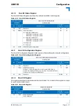
The Interface Configuration Register holds a series of bits defining the Ethernet, PCI Express
(PCIe) and Serial RapidIO (sRIO) configurations.

Table 4-11: Interface Configuration Register

REGISTER NAME

INTERFACE CONFIGURATION REGISTER

ADDRESS

0xEC00_0008

BIT

NAME

DESCRIPTION

RESET 

VALUE

ACCESS

7

CFV

Configuration Valid:

0 = Configuration of registers not finished by MMC
1 = Configuration of registers finished by MMC

0

R

6 - 4

Res.

Reserved

000

R

3 - 1

SDT

CPU SerDes type:

000 = SerDes 1/2 disabled
001 = x4 PCIe 
010 = Reserved
011 = Reserved
100 = Reserved
101 = sRIO 3.125 Gbit
110 = sRIO 1.25 Gbit
111 = sRIO 2.5 Gbit

N/A

R

0

SC

CPU SerDes configuration:

0 = PCIe end point / sRIO slave 
1 = PCIe route complex / sRIO master

N/A

R

Summary of Contents for AM4100

Page 1: ...If it s embedded it s Kontron User Guide P R E L I M I N A R Y AM4100 Single Mid and Full Size AMC Module based on the Freescale MPC8641D Dual Core PowerPC Processor Doc ID 36126 Rev 2 0 May 11 2011...

Page 2: ...s reserved All data is for information purposes only and not guaranteed for legal purposes Information has been carefully checked and is believed to be accurate however no responsibility is assumed fo...

Page 3: ...ons xv Special Handling and Unpacking Instructions xv General Instructions on Usage xvi Two Year Warranty xvii 1 Introduction 1 3 1 1 Board Overview 1 3 1 2 Board Specific Information 1 4 1 3 System R...

Page 4: ...Ethernet Connectors 2 12 2 4 AMC Interconnection 2 13 2 4 1 Fabric Interface 2 13 2 4 2 Synchronization Clock Interface 2 15 2 4 3 System Management Interface 2 15 2 4 4 JTAG Interface 2 15 2 4 5 Mod...

Page 5: ...6 2 Interface Configuration Register 4 10 4 6 3 POST Code Register 4 11 4 6 4 Firmware Configuration Register 4 11 4 6 5 MMC I O Status Register 4 12 4 6 6 Watchdog Timer Control Register 4 13 4 6 7...

Page 6: ...TFTP FTP Server Access 5 7 5 3 4 NBL Flash Operation 5 7 5 3 5 Motorola S Records 5 8 5 4 Operating the NetBootLoader 5 8 5 4 1 Initial Setup 5 8 5 4 2 Accessing the NetBootLoader 5 8 5 4 3 NetBootLoa...

Page 7: ...4 6 2 3 Module Management Power Consumption 6 4 6 3 Payload Power Consumption of the AM4100 6 4 6 4 IPMI FRU Payload Power Consumption 6 5 6 5 Payload Start Up Current of the AM4100 6 5 7 Thermal Con...

Page 8: ...Preface AM4100 Page viii ID 36126 Rev 2 0 P R E L I M I N A R Y This page has been intentionally left blank...

Page 9: ...ded Options Region Pins Description 2 20 2 10 JTAG Pins Description 2 20 2 11 Processor Supervision 2 22 2 12 AMC Specific Signals 2 22 2 13 Onboard Power Supply Supervision 2 22 2 14 Temperature Sign...

Page 10: ...d Status Register 4 22 4 27 MMC Configuration Register 4 23 5 1 NetBootLoader Control Commands 5 5 5 2 System Status Monitoring Commands 5 6 5 3 TFTP FTP Server Commands 5 7 5 4 NBL Flash Operation Co...

Page 11: ...Port Mapping 2 14 4 1 SW2 DIP Switch 4 3 4 2 SW3 DIP Switch 4 5 7 1 Processor Temperature Sensor Placement AM4100 Top View 7 3 7 2 Board Temperature Sensor Placement AM4100 Bottom View 7 3 7 3 Operati...

Page 12: ...Preface AM4100 This page has been intentionally left blank Page xii ID 36126 Rev 2 0 P R E L I M I N A R Y...

Page 13: ...f any circuit product or example shown in this document Kontron reserves the right to change modify or improve this document or the product described herein as seen fit by Kontron without further noti...

Page 14: ...ensitive Device This symbol and title inform that electronic boards and their compo nents are sensitive to static electricity Therefore care must be taken during all handling operations and inspection...

Page 15: ...hing the product with his her hands or tools This is most easily done by touching a metal part of your system housing Warning All operations on this device must be carried out by sufficiently skilled...

Page 16: ...echnical Support as a special han dling instruction will void your warranty This device should only be installed in or connected to systems that fulfill all necessary techni cal and specific environme...

Page 17: ...und the original cost of purchase if appropriate In the event of repair refunding or replacement of any part the ownership of the removed or replaced parts reverts to Kontron and the remaining part of...

Page 18: ...Preface AM4100 This page has been intentionally left blank Page xviii ID 36126 Rev 2 0 P R E L I M I N A R Y...

Page 19: ...AM4100 Introduction ID 36126 Rev 2 0 Page 1 1 Introduction Chapter 1 1 P R E L I M I N A R Y...

Page 20: ...Introduction AM4100 Page 1 2 ID 36126 Rev 2 0 P R E L I M I N A R Y This page has been intentionally left blank...

Page 21: ...dedicated Module Management Controller MMC is used to manage the board and support a defined subset of Intelligent Platform Management Interface IPMI commands and PICMG ATCA AMC command extensions wh...

Page 22: ...rface in the Fat Pipes Region operates as host or as agent Two Gigabit SerDes connections in the Fat Pipes Region optional Serial port in the Extended Options Region Debug port in the Extended Options...

Page 23: ...lane with the following AMC Card edge connector port mapping Common Options Region ports 0 1 Two Gigabit Ethernet SerDes ports Fat Pipes Region ports 4 7 One x4 PCI Express interface or alternatively...

Page 24: ...AM EEP 64 kbit Temp Sense AMC Card edge Con Port No 0 1 DC DC converters 12V payload Clocks 15 IPMB L Local bus Ctrl TSEC 1 TSEC 3 TSEC 2 RGMII RGMII RGMII S E R D E S TSEC 4 DDR2 Local bus 16bit DMA...

Page 25: ...the user on the hot swap state of the module The HS LED states are off short blink long blink and on User Specific LEDs ULED3 red green amber AMC Eth port A link signal status or POST code LED ULED2...

Page 26: ...ure 1 3 AM4100 Board Layout Top View Figure 1 4 AM4100 Board Layout Bottom View MPC8641D SoC J1 1 85 GbE PHY J4 DDR2 Memory NBL Flash NBL Flash J3 GbE A J2 GbE B Hot Swap Microswitch DDR2 Memory J5 J1...

Page 27: ...h chips 2 x 4 MB Mass Storage Device Up to 4 GB NAND Flash via an onboard IDE Flash Controller Serial EEPROM with 64 kbit AMC Interconnection Gigabit Ethernet Common Options Region ports 0 1 Two Gigab...

Page 28: ...40 kB RAM and redundant 512 kB MMC Firmware Flash with automatic roll back strategy The MMC carries out IPMI commands such as monitoring several on board temperature conditions board voltages and the...

Page 29: ...and Play capability PCI Express device enumeration NetBootLoader NBL Firmware parameters are saved in the EEPROM Board serial number is saved within the EEPROM Software IPMI Module Management Controll...

Page 30: ...s 3 directions x y z Vibration random transporta tion GR 63 CORE EN300019 2 2 IEC60068 2 64 5 20 Hz 0 01 g Hz ASD 20 200 Hz 3 dB slope 8 8 m s RMS acceleration 30 min test time axis 3 directions x y z...

Page 31: ...n five minutes Otherwise condensation may cause irre versible damage especially when the board is powered up again Kontron does not accept any responsibility for damage to products resulting from dest...

Page 32: ...Introduction AM4100 Page 1 14 ID 36126 Rev 2 0 P R E L I M I N A R Y This page has been intentionally left blank...

Page 33: ...AM4100 Functional Description ID 36126 Rev 2 0 Page 2 1 Functional Description Chapter 1 2 P R E L I M I N A R Y...

Page 34: ...Functional Description AM4100 Page 2 2 ID 36126 Rev 2 0 P R E L I M I N A R Y This page has been intentionally left blank...

Page 35: ...computing and outstanding dual core performance with low power consumption and high system integration The MPC8641D processor supports symmetric multiprocessing SMP and asymmetric multi processing AM...

Page 36: ...interfaces SIN SOUT RTS CTS Programming model compatible with the original 16450 UART and the PC 16550D IEEE 1149 1 compliant JTAG boundary scan 2 1 2 Memory The AM4100 supports a single channel 72 b...

Page 37: ...s after the threshold voltag es have been passed 2 2 4 Flash Memory There are three Flash devices available as described below two for the NetBootLoader and one for the NAND Flash Disk Controller 2 2...

Page 38: ...odule Management LEDs and four User Specific LEDs The User Specific LEDs can be configured via two onboard registers see section 4 6 14 User Specific LED Configuration Register Figure 2 1 Front Panel...

Page 39: ...r or user On module out of service Pulsing traffic on the IPMB L bus LED2 red Any action health error detected Depends on carrier or user green Any action no health error detected red green Blinking s...

Page 40: ...105 C green POST bit 3 and bit 7 AMC Ethernet port A link signal status ULED2 red When lit up during power on it indicates a clock failure processor overtemperature above 105 C green POST bit 2 and b...

Page 41: ...ow nibble state 2 is followed by state 0 Note Under normal operating conditions the User Specific LEDs should not remain lit during boot up They are intended to be used only for debug purposes In the...

Page 42: ...20P 1H is in cluded to facilitate software debugging using an emulation probe The following table provides pinout information for the debug connector J5 Table 2 4 Debug Connector J5 Pinout PIN SIGNAL...

Page 43: ...s SerDes ports Channels 2 and 4 can be directed to the front panel RJ45 connector In certain board versions these channels are configured as SerDes ports and directed to the AMC ports 8 9 in the Exten...

Page 44: ...a valid link has not been established due to a missing or a faulty cable connection SPEED green yellow This LED lights up to indicate a successful 100Base TX or 1000BASE T connection When green it ind...

Page 45: ...Fabric Interface The Fabric interface is the real communication path and comprises 20 high speed ports pro viding point to point connectivity for module to carrier and module to module implementations...

Page 46: ...tions Region GbE A GbE B x4 PCI Express AM4100 w x4 PCIe Port Mapping not used not used not used Fat Pipes Region PCI Express Reference Clock TCLKC D System Tick optional GbE C optional Debug LVTTL Se...

Page 47: ...t from the module to the carrier via the Local Intelli gent Platform Management Bus IPMB L The Module Management Controller uses this port for the communication with the Carrier Intelligent Platform M...

Page 48: ...und 164 GND Logic Ground 8 RSV Reserved 163 Tx20 Not Connected AMC 9 PWR Payload Power Carrier 162 Tx20 Not Connected AMC 10 GND Logic Ground 161 GND Logic Ground 11 Tx0 GbE A Transmitter AMC 160 Rx20...

Page 49: ...r 42 PWR Payload Power Carrier 129 Rx15 Not Connected AMC 43 GND Logic Ground 128 GND Logic Ground 44 Tx4 PCIe 0 Transmitter Serial RapidIO 0 Trans mitter AMC 127 Tx14 Reserved for debug serial data o...

Page 50: ...gic Ground 110 GND Logic Ground 62 Rx6 PCIe 2 Receiver Serial RapidIO 2 Receiver Carrier 109 Tx11 Not Connected AMC 63 Rx6 PCIe 2 Receiver Serial RapidIO 2 Receiver Carrier 108 Tx11 Not Connected AMC...

Page 51: ...ound 92 GND Logic Ground 80 FCLKA PCIe Reference Clock Carrier 91 Tx8 GbE C Transmitter AMC 81 FCLKA PCIe Reference Clock Carrier 90 Tx8 GbE C Transmitter AMC 82 GND Logic Ground 89 GND Logic Ground 8...

Page 52: ...9 Extended Options Region Pins Description AMC PIN AMC PORT FUNCTION I O SIGNALING VOLTAGE 133 15 Tx serial port SER1 O 3 3V TTL level 132 15 Rx serial port SER1 I 3 3V TTL level 127 14 Reserved for...

Page 53: ...boot parameters The MMC is used to manage the AM4100 for example it monitors several onboard tempera ture conditions board voltages and the power supply status manages hot swap LEDs and op erations r...

Page 54: ...Hot swap LED Control LED Hot swap switch Status of hot swap switch Monitor switch User specific LED Basic feedback about failures Control user specific LED Gigabit Ethernet A B Gigabit Ethernet link s...

Page 55: ...C sensor temperature Inlet board temperature sensor near the AMC Card edge connector Monitor temperature Outlet AMC sensor temperature Outlet board temperature sensor near the AMC Card edge connector...

Page 56: ...Functional Description AM4100 Page 2 24 ID 36126 Rev 2 0 P R E L I M I N A R Y This page has been intentionally left blank...

Page 57: ...AM4100 Installation ID 36126 Rev 2 0 Page 3 1 Installation Chapter 1 3 P R E L I M I N A R Y...

Page 58: ...Installation AM4100 This page has been intentionally left blank Page 3 2 ID 36126 Rev 2 0 P R E L I M I N A R Y...

Page 59: ...stallation or to unlock and pull it out of the chassis carrier during removal When installing or remov ing the board apply only as much force as required to lock unlock the board or to pull the board...

Page 60: ...rd is seated in the AMC carrier backplane connector 3 Using minimal force push the extractor locking handle towards the board until fully re tracted 4 Connect all external interfacing cables to the bo...

Page 61: ...g handle has three positions retracted locked mid position hot swap microswitch disengaged and extended unlocked During operation the han dle is in the retracted position In this position the board is...

Page 62: ...to Chapter 4 3 To install the AM4100 perform the following 1 Ensure that the board extractor locking handle is fully extended away from the board 2 Carefully insert the board into the slot designated...

Page 63: ...the BLUE HS LED will be turned off If the module FRU information is invalid or the carrier cannot provide the necessary payload power the hot swap process is stopped and the BLUE HS LED keeps blinkin...

Page 64: ...Installation AM4100 This page has been intentionally left blank Page 3 8 ID 36126 Rev 2 0 P R E L I M I N A R Y...

Page 65: ...AM4100 Configuration ID 36126 Rev 2 0 Page 4 1 Configuration Chapter 1 4 P R E L I M I N A R Y...

Page 66: ...Configuration AM4100 This page has been intentionally left blank Page 4 2 ID 36126 Rev 2 0 P R E L I M I N A R Y...

Page 67: ...NetBootLoader NBL Firmware Flash configuration and switch 4 for configuring the low memory address offset mode of the e600 core 1 Switch 3 is reserved for future use Figure 4 1 SW2 DIP Switch The foll...

Page 68: ...s in the OFF position switching to the ON position will force the use of the redundant Flash during the next boot op eration 4 1 1 3 Core 1 LM Address Offset Mode Configuration Switch 4 controls the o...

Page 69: ...dicates the functions of the two switches integrated in the SW3 DIP switch For further information refer to the IPMI FW User Guide for the AM4100 Module provided with the documentation CD Table 4 5 SW...

Page 70: ...pt Setting IRQ STANDARD FUNCTION IRQ0 Reserved PCIe1 INTA IRQ1 Reserved PCIe1 INTB IRQ2 Reserved PCIe1 INTC IRQ3 Reserved PCIe1 INTD IRQ4 Reserved PCIe2 INTA IRQ5 Reserved PCIe2 INTB IRQ6 Reserved PCI...

Page 71: ...00 0x0_FDFF_FFFF currently used Flash 32MB LCS1 16bit NOR Flash 0 NOR Flash 1 0x0_F800_0000 0x0_FBFF_FFFF redundant Flash 64MB LCS2 16bit NOR Flash 1 NOR Flash 0 0x0_F400_0000 0x0_F7FF_FFFF 64MB LCS3...

Page 72: ...2 Watchdog Timer Control Register 0xEC00_0283 AMC Geographic Addressing Register 0xEC00_0284 Board and Logic Revision Register 0xEC00_0285 Host Reset Status Command Register 0xEC00_0286 Host I O Statu...

Page 73: ...te Take care when modifying the contents of these registers as the NetBootLoader may be relying on the state of the bits under its control Table 4 10 Memory Configuration Register REGISTER NAME MEMORY...

Page 74: ...ME INTERFACE CONFIGURATION REGISTER ADDRESS 0xEC00_0008 BIT NAME DESCRIPTION RESET VALUE ACCESS 7 CFV Configuration Valid 0 Configuration of registers not finished by MMC 1 Configuration of registers...

Page 75: ...read only and can be configured only by the Module Management Controller Table 4 12 POST Code Register REGISTER NAME POST CODE REGISTER ADDRESS 0xEC00_0080 BIT NAME DESCRIPTION RESET VALUE ACCESS 7 0...

Page 76: ...MMC AMC Extended Options Region configuration 0 AMC Extended Options Region is disabled 1 AMC Extended Options Region is enabled With this bit the SER1 port and the debug port of the AMC Extended Opti...

Page 77: ...iod Nor mally the Watchdog is retriggered by writing a 1 to the WTR bit In the event a timeout occurs the WTE bit is set to 1 This bit can then be polled by the application and handled accordingly To...

Page 78: ...trol bit 0 Watchdog Timer has not been enabled Prior to the Watchdog being enabled this bit is known as WEN After the Watchdog is enabled it is known as WTR Once the Watchdog Timer has been enabled th...

Page 79: ...ue 0x00 for the initial board prototypes and will be incremented with each changed in hardware as development continues Table 4 16 AMC Geographic Addressing Register REGISTER NAME AMC GEOGRAPHIC ADDRE...

Page 80: ...nerated by software warm reset 1 System host reset generated by power on cold reset Writing a 1 to this bit clears this bit N A R W 6 5 Res Reserved 00 R 4 SYRST Forced system host reset 0 No action 1...

Page 81: ...Flash boot status 00 Boot from NOR Flash 0 NOR Flash 0 is mapped to LCS1 NOR Flash 1 is mapped to LCS2 01 Boot from NOR Flash 1 NOR Flash 0 is mapped to LCS2 NOR Flash 1 is mapped to LCS1 10 Reserved...

Page 82: ...Hardware reset red ULED2 Clock fail red ULED3 Power fail red Table 4 22 Hot Swap Status Register REGISTER NAME HOT SWAP STATUS REGISTER ADDRESS 0xEC00_028A BIT NAME DESCRIPTION RESET VALUE ACCESS 7 Re...

Page 83: ...green 3 Configured for MODE B the User Specific LEDs are dedicated to functions as follows ULED0 User Specific LED 0 controlled by MMC red green ULED1 User Specific LED 1 controlled by MMC red green U...

Page 84: ...LED command 0000 Get User Specific LED 0 0001 Get User Specific LED 1 0010 0111 Reserved 1000 Set User Specific LED 0 1001 Set User Specific LED 1 1010 1111 Reserved 0000 R W 3 0 ULCOL User Specific L...

Page 85: ...EGISTER NAME SERIAL OVER LAN CONFIGURATION REGISTER ADDRESS 0xEC00_028E BIT NAME DESCRIPTION RESET VALUE ACCESS 7 4 SCOM Host SER0 port configuration for serial over LAN 0000 SER0 is routed to the fro...

Page 86: ...ne the timer capability Therefore writing a 0 to the Delay Timer Control and Status Register followed by reading indicates the timer capability not the timer outputs For example writing 0x00 and then...

Page 87: ...figured as SMI interrupt Table 4 27 MMC Configuration Register REGISTER NAME MMC CONFIGURATION REGISTER ADDRESS 0xEC00_029C BIT NAME DESCRIPTION RESET VALUE ACCESS 7 MPGC MMC program request 0 No acti...

Page 88: ...Configuration AM4100 This page has been intentionally left blank Page 4 24 ID 36126 Rev 2 0 P R E L I M I N A R Y...

Page 89: ...AM4100 NetBootLoader ID 36126 Rev 2 0 Page 5 1 NetBootLoader Chapter 1 5 P R E L I M I N A R Y...

Page 90: ...NetBootLoader AM4100 This page has been intentionally left blank Page 5 2 ID 36126 Rev 2 0 P R E L I M I N A R Y...

Page 91: ...takes place the image is copied into DDR2 SDRAM and control is passed to the application If the NetBootLoader does not find a valid image or operator intervention has oc curred control is passed to t...

Page 92: ...ay inter face with a terminal emulator 5 2 2 SER1 Serial Interface The SER1 serial port is used to provide the NetBootLoader with the ability to access Motorola S Records for programming an image to N...

Page 93: ...thernet port parameters Requires that a DHCP or BOOTP server be available in the same network as the AM4100 FDT Enable or disable FDT Generates a flattened device tree for OS HELP or Display online HE...

Page 94: ...is configured the commands TFTP and FTP are available to download bootable images or other files as required 5 3 3 1 DHCP BOOTP Server Access Use of this access method requires the availability of ei...

Page 95: ...e provides an overview of the available NBL Flash memory opera tion functions Table 5 3 TFTP FTP Server Commands CMD TITLE ALIAS FUNCTION REMARKS BYE Terminate session with FTP server CD Change Direct...

Page 96: ...provide information on how to set up and operate the NetBootLoader itself initiation of the telnet interface and how to program an image to the NBL Flash memory 5 4 2 Accessing the NetBootLoader Init...

Page 97: ...tBootLoader for interfacing operations These commands are BW BootWait CBL Change Bootline DHCP FDT NET PASSWD PF Port Format SCRIPT SQ Boot Sequence Default settings are available for all the above co...

Page 98: ...thernet interfaces are only available after these settings have been made 5 4 3 6 PASSWD This command is used to set the password used by the NetBootLoader for the operation of the telnet interface No...

Page 99: ...word If the password is valid the operator can now access the NetBootLoader If the password is invalid the telnet login procedure is terminated and the boot operation continues In the case of an inval...

Page 100: ...ecutable PPC code must be at offset 0x0 FDT enabled or 0x100 FDT disabled Gaining access to the image for programming to NBL Flash memory depends on where it is located The NetBootLoader can access fo...

Page 101: ...must be at address 0x0 FDT enabled or 0x100 FDT disabled If S1 or S2 record input is preferred please note that these records only include 16 and 24 bit wide addresses For accessing the Motorola S Rec...

Page 102: ...the session is finished 5 5 Plug and Play The AM4100 NetBootLoader includes Plug and Play functionality This ensures that the board is completely initialized and that all resources necessary for PCI...

Page 103: ...r boot operation SYNTAX abort DESCRIPTION This command is used by the operator to terminate the boot operation during the boot wait time to allow the operator to perform other NetBootLoader operations...

Page 104: ...LED ULED0 blinks green slowly Therefore if the boot wait is set to 2 seconds the LED will only blink approximately four times The option f is used to force updating of the CRC value of boot section o...

Page 105: ...rs x x defines the bootline to be used with the kernel indicated by num or the common bootline DESCRIPTION When an image is programmed to NBL Flash memory it is assigned an ID number 0 1 2 or 3 This n...

Page 106: ...string x x new directory path DESCRIPTION If an FTP server session has been established with the LOGIN command the command CD is used to change the current FTP server directory The argument new path m...

Page 107: ...h the image The CHECK command provides status information for the current images in NBL Flash memory USAGE Verify valid image is stored in NBL Flash memory COMMAND RESPONSE check Checking Image 0 chec...

Page 108: ...option is used with the SCRIPT command to confirm that cloning is to be performed DESCRIPTION To update the NetBootLoader itself the command CLONE is used The image source for programming is the data...

Page 109: ...e current NetBootLoader in the fallback flash are you sure no yes clone System transferred to fallback flash NetBtLd Note When responding to the overwrite query yes must be spelled out Any other respo...

Page 110: ...terface is inoperable The initial configuration must be done either manually from the SER0 interface using the command NET or if a DHCP or BOOTP server is available it can be done automatically by the...

Page 111: ...of an FDT image is booted from 0x0 when not specified displays current setting DESCRIPTION This command is used to specify the creation of an FDT for an operating system if required An FDT is require...

Page 112: ...r string 0 1 2 3 ID number of the image for which FDT information is to be displayed no other values than those above are supported when not specified displays FDT information for image 0 DESCRIPTION...

Page 113: ...t before a file can be downloaded and the file must be in binary format The argument filename must refer to an existing and accessible file on the server and the syntax must follow the requirements on...

Page 114: ...ader and the programmed images This information is displayed in hexadecimal offsets Images programmed using the o option of the command LF are not shown USAGE Display system information COMMAND RESPON...

Page 115: ...s adr parameter hexadecimal x x absolute address of image to be programmed l option length len parameter hexadecimal x x length of image to be programmed DESCRIPTION If num is not specified 0 is assum...

Page 116: ...used to retain the surrounding data however this slows down the operation significantly To achieve fast programming of parameter images without destroying other NBL Flash memory contents the data sho...

Page 117: ...o establish an FTP server session The password parameter is not necessary if the server does not require one USAGE Initiate FTP server session COMMAND RESPONSE login 192 168 47 12 johndoe mypassword R...

Page 118: ...then made to program the NBL Flash memory after the LS command has been issued it will fail MD FUNCTION Display visible memory SYNTAX md adr where md command adr parameter hexadecimal x x starting ad...

Page 119: ...1 n logical identifier of Ethernet port addressed by this command where 0 TSEC1 1 TSEC2 2 TSEC3 3 TSEC4 ip addr parameter string nnn nnn nnn nnn IP address of AM4100 netmask option netmask netmask pa...

Page 120: ...f Using the f option forces a CRC to be performed and stored along with the other configuration parameters in the serial EEPROM Once the configuration of an Ethernet port is done it is available for o...

Page 121: ...esponds with an appropriate request to the operator which must be properly acknowledged or the operation fails refer to USAGE below To set the password in the event it is unknown use the option f This...

Page 122: ...ed IRQ number PF FUNCTION Set or display the serial port parameters format SYNTAX pf port baud bitschar parity stops where pf command port parameter string ser0 or ser1 defines serial port to be confi...

Page 123: ...ters are used for the operator con sole Issuing this command without parameters being specified will display the current serial port settings Syntax wise no spaces are permitted between the parameters...

Page 124: ...packets in seconds DESCRIPTION To verify the operational status of an Ethernet interface the command PING is used This command tests the network connection and target server s ability to respond If n...

Page 125: ...oad the contents of the data buffer to a file on an FTP server the command PUT is used The file indicated by the parameter filename is created on the server In the event that a file with this name alr...

Page 126: ...ets the entire system If this command is issued over a remote telnet connection the telnet session is terminated prior to the generation of the reset RUN FUNCTION Loads and starts a bootable image SYN...

Page 127: ...the boot process During booting if a valid script is available the NetBootLoader will process it once the boot wait time is expired If this command is issued without any parameters the currently acti...

Page 128: ...or area of visible mem ory to be stored to the data buffer m option memory address adr parameter hexadecimal x x absolute address of image to be programmed num parameter numerical string 0 1 2 3 numbe...

Page 129: ...instead of SER0 DESCRIPTION With the command SL Motorola S Records are downloaded to the data buffer and the record addresses modified accordingly as required for DDR2 SDRAM operation for copying to...

Page 130: ...y The boot sequence defines to the NetBootLoader the order in which images are to be accessed when booting The NetBootLoader starts with num1 and continues until a valid image is found In the case tha...

Page 131: ...n is to be swapped the SWAP command is invoked with the t option temporary at the next power on the configuration reverts to the previous setting or the p option permanently The current configuration...

Page 132: ...E NetBtLd swap t Flash config swapped till next reboot via HOST bit NetBtLd NetBtLd swap Active Flash is NOR flash 1 Fallback Flash is NOR flash 0 Configuration Details IPMI straight HOST reverse DIP...

Page 133: ...le to download a file from a TFTP server via an Ethernet port If used with the DHCP command it is possible to use the IP address and file information returned by the DHCP command If this command is is...

Page 134: ...NetBootLoader AM4100 This page has been intentionally left blank Page 5 46 ID 36126 Rev 2 0 P R E L I M I N A R Y...

Page 135: ...AM4100 Power Considerations ID 36126 Rev 2 0 Page 6 1 Power Considerations Chapter 1 6 P R E L I M I N A R Y...

Page 136: ...Power Considerations AM4100 This page has been intentionally left blank Page 6 2 ID 36126 Rev 2 0 P R E L I M I N A R Y...

Page 137: ...hould be selected at the higher end of the specified voltage range The continuous current limit value is based on the power limit of 60 W per module at the minimum supply value The maximum current val...

Page 138: ...rations and applications The processor and the memory dissipate the majority of the payload power The payload power consumption tables below list the voltage and power specifications for the AM4100 bo...

Page 139: ...information on the start up current contact Kontron s Technical Support Table 6 2 Power Consumption AM4100 MPC8641D 1 0 GHz 400 MHz Platform Freq AIRFLOW 3 m s 2 5 m s 2 m s 1 5 m s 1 m s 0 6 m s POWE...

Page 140: ...Power Considerations AM4100 This page has been intentionally left blank Page 6 6 ID 36126 Rev 2 0 P R E L I M I N A R Y...

Page 141: ...AM4100 Thermal Considerations ID 36126 Rev 2 0 Page 7 1 Thermal Considerations Chapter 1 7 P R E L I M I N A R Y...

Page 142: ...Thermal Considerations AM4100 This page has been intentionally left blank Page 7 2 ID 36126 Rev 2 0 P R E L I M I N A R Y...

Page 143: ...ent damage to the board To ensure functionality at the maximum temperature the Module Management Controller supports several temperature monitoring and control features The AM4100 includes five temper...

Page 144: ...sor types is as follows Freescale MPC8641D all versions 105 C 7 2 CPU Internal Thermal Regulation The Instruction Cache Throttling mechanism allows for the reduction of the CPU s power con sumption an...

Page 145: ...ature or at a reduced flow rate and still provide some margin for temporarily requested peak performance before thermal protection will be activated How to read the diagram Select a specific CPU and c...

Page 146: ...NBench benchmark software running under Linux Both processor cores were enabled during the measurements Figure 7 3 Operational Limits for the Mid Size AM4100 with 1 0 GHz Note The maximum airflow inpu...

Page 147: ...Operational Limits for the Mid Size AM4100 with 1 32 GHz Figure 7 5 Operational Limits for the Full Size AM4100 with 1 5 GHz Workload level 99 both cores Volumetric Flow Rate m h 3 Volumetric Flow Ra...

Page 148: ...epends on individual configuration of the AMC carrier or MicroTCA system The following figure shows the impedance curves of a Mid size and a Full size AM4100 mod ule Figure 7 6 Mid Size and Full Size...

Page 149: ...wing table indicates the deviation of the airflow rate on a Mid size AM4100 module Table 7 2 Deviation of the Airflow Rate on a Mid Size AM4100 VOLUMETRIC FLOW RATE CFM DEVIATION OF THE AIRFLOW RATE Z...

Page 150: ...AIRFLOW RATE ZONE A ZONE B ZONE C ZONE D 10 2 83 0 43 1 98 1 29 20 2 58 0 29 1 43 1 43 30 2 87 0 57 1 72 1 72 40 2 80 0 50 1 51 1 79 Note The Full size AM4100 module has an airflow rate deviation of m...

Reviews: