
Board Features
14
the M5 state. When main RTM payload power is successfully removed from the RTM slot, the Hot
Swap LED remains lit, indicating it is safe to remove the RTM from the chassis.
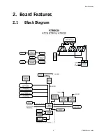
2.8
Debugging Features
2.8.1
IPMI controlled LED (LED3)
The green Management LED represents the MMC heart beat when it blinks slowly.
The blinking amber or yellow Management LED represents MMC communication over IPMB-L when
pulsing.
2.8.2
RTM Health (LED2)
The green LED indicates that the RTM is working properly.
The amber LED indicates that the RTM is in fault.
2.8.3
Out of service (LED1)
When this LED is off, it indicates that the board is working properly.
When this LED is on, it indicates a major fault or an RTM malfunction.
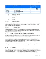
LED Status
Meaning
Off
Normal status
Blinking Blue
Preparing for removal/insertion: Long blink indicates activation is in progress, short blink
when deactivation is in progress.
Solid Blue
Ready for hot swap


