y
Alarm Input Pin:
Please refer to the schematic diagram in Figure 3 for how the external detector collects
alarm information.
PIR
Switch
Input pins
PIR Power
Figure 3
The detector should be a switched type (always on or always off). If the detector has detected smoke, or
people or animals entering the area, the detector will switch on or switch off and it will send the external
alarm signal to the IP camera.
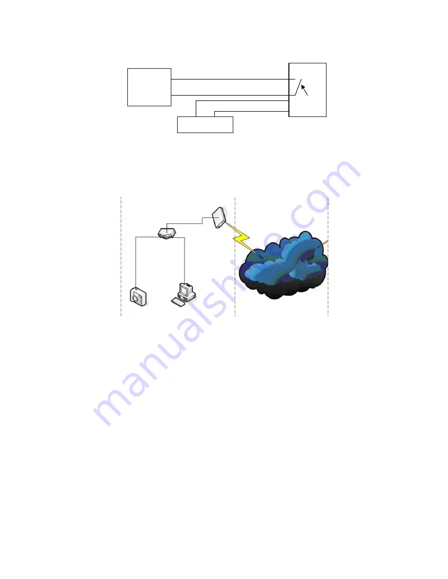
Connecting to the Network
LAN IP: 192.168.0.1
WAN IP: 202.96.82.177
Internet
ADSL
Modem
Router-1
PC-1
192.168.0.175
IP Camera-1
192.168.1.139
Home
Figure 4
Connection Instructions
Before visiting the IP Camera, connect it to the network first, supply power to it, and check if the light of the
RJ45 Socket is normal to make sure all of the communication links are fluent. The connection method is like
that of Figure 4.
Setting the IP Address
The IP addresses of the IP Camera and PC should be at the same segment. The example in Figure 5.1
shows that IP Camera-1 can’t be visited. Run BSearch_en.exe in the CD, click the Search button, and then
select IP Camera-1 to reset the IP address, as shown in Figure 5.2.
Setup Instructions:
y
Carefully check the “Local PC information” on the top left corner which lists the PC configuration. If there
are several network adapters in the PC, please select the one you are using and make sure the IP
address of the IP Camera is at the same segment of the PC.
y
Change the content of “IP config” on the right to make sure that the content is the same as “Local PC
information”. You only need to set the last section of the IP address, you can set it as 139 just like the
example in Figure 5.2.
y
If you don’t know how to fill out the contents of “IP config”, you could also tick “Set IP
automatically” to automatically get the IP address from the router.
3


