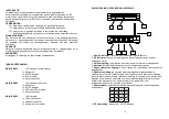
INTRODUCTION:
This wireless microphone system uses advanced wireless communication
technology to deliver consistently high quality audio up to 100 meters in open
area and 30 meters through walls and ceilings. The PLL (Phase Locked Loop)
circuit controls the strength and quality of the signal.
REMARKS:
1) Always use transmitter and receiver on the same frequency
2) Do not use two transmitters with same frequency.
3) Enlarge, to avoid possible interference, the distance between the
channels when using two or more systems at the same time.
WARNING
:
To reduce risk of electric shock, this product should ONLY be opened by an
authorized technician if service is required. Disconnect the product from mains
and other equipment if a problem should occur. Do not expose the product to
water or moisture.
WARRANTY:
No guarantee or liability can be accepted for any changes and modifications of
the product or damage caused due to incorrect use of this product.
GENERAL:
Designs and specifications are subject to change without notice.
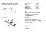
PACKAGING CONTENTS:
KN
-MICW410
1x Receiver (non-diversity)
1x
Microphone
1x
AC/DC
adapter
1x
6.3mm
cable
1x
Accesory
set
KN
-MICW420
1x Receiver (diversity)
1x
Microphone
1x
AC/DC
adapter
1x XLR to 6.3mm cable
1x
Accesory
set
KN-
MICW430
1x Bodypack
1x
Clip-on
microphone
1x
Headset
microphone
1x Instrument (line) cable
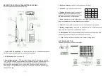
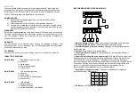
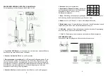
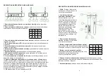
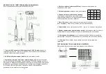
DESCRIPTION RECEIVER
KN
-MICW410:
1.
Power indicator:
lights up when receiver is on
2.
RF indicator:
lights up to indicate that signal is receiving
3.
Volume control:
controls the volume output of the receiver
4.
Antenna:
fixed antenna for receiving signals
5.
Unbalanced output:
6,3mm output for connecting to mixer or amplifier
6.
Squelch adjustment:
The squelch adjusts the output level to suppress the
noise. Turn the button to the right for maximum adjustment with minimum noise
interference. With this adjustment the range of the system is limited. Turn the
button to the left for maximum range of the system but with possible noise
interference (use mini screwdriver from the accessory set to adjust)
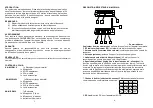
7.
Channel selector:
select the channel with the following combinations of the
switches
8.
DC Jack:
DC input for AC/DC adapter
1
.
5
6
7
8
1
2
3
4
CH
1
CH
2
CH
3
CH
4
CH
5
CH
6
CH
7
CH
8
CH
9
CH
10
CH
11
CH
12
CH
13
CH
14
CH
15
CH
16
2
.


