CHECK, MAINTAIN, CLEAN
- Always carry out maintenance work under unloaded condition.
- Watch out for possible hazards during maintenance work (bumping, falling down).
- Use a slightly damp cloth and a non-abrasive cleaning agent for cleaning.
TECHNICAL DATA / SPECIFICATIONS
Material
Tubes, angle: steel, powder-coated black
Screws, washers, threads: galvanised steel
Plastic parts: PA, PE, TPE black
Dimensions
Threaded connection: 3/8" and 5/8"
Arm: 240-400 mm - 160 mm adjustment range
Height: 268-418 mm - 150 mm adjustment range
Weight
1.61
Cardboard
inside: 380 x 136 x 57 mm
KÖNIG & MEYER
GmbH & Co. KG
Kiesweg 2, 97877 Wertheim, www.k-m.de
18807-000-55 Rev.07 03-80-379-00 7/20
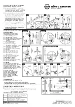
4. MOUNTING THE STAND/EXTENSION TUBE
Assembly of the individual components
4.1
Boom arm and adjustable tube cpl.
b
are already
4.1
pre-assembled ex-factory. The removal of the
4.1
screw
b.1
enables the separation of both tubes,
4.1
e.g. for maintenance or cleaning purposes.
4.2
Insert bolts of the stand/extension tube
a
into
4.2
the holder of the adjustable tube
b
and secure
4.2
connection by screwing the set screw
f
.
4.2
Use Allen key SW3
i
for this purpose.
4.2
The set screw has to be screwed in the stand/
4.2
extension tube until you can still turn the set
4.2
screw but not remove it. Subsequently tighten
4.2
the clamping screw
e
.
4.3
At the upper end of the extension tube you will find
4.3
a.2
an ex-factory mounted 5/8" reduction thread.
4.3
However, if the ACCESSORIES
6
are furnished
4.3
with 3/8" threaded bushes, remove the above-
4.3
mentioned reduction thread and use the 3/8"
4.3
threaded bolt together with the thumb wheel that is
4.3
firmly connected to the standtube.
USER INSTRUCTIONS / FUNCTIONS
5. SETTINGS
Undertake setting(s) changes if necessary,
under unloaded condition.
5.1 HEIGHT - EXTRACTION (0-150 mm)
5.1.1
Slightly loosen clamping nut
a.1
.
5.1.2
Slide the pull-out to the desired position.
5.1.3
Then retighten the clamping nut.
5.2 HEIGHT - FASTENING
5.2
(only for 18810, 18820)
5.2.1
Loosen both clamping nuts
g
of
5.2.1
the clamping angle with slots
c
.
5.2.2
Position boom/adjustment
b
and
5.2.2
clamping angle with slots
c
.
5.2.3
Tighten the clamping nuts again.
5.3 DIRECTION
5.3.1
Loosen clamping screw
e
slightly.
5.3.2
If necessary, also loosen set screw
f
.
5.3.3
Turn the universal holder in chosen
5.3.3
direction.
5.3.4
Retighten the clamping screw.
5.3.5
If necessary, tighten set screw
f
.
5.4 DISTANCE of LOADING
5.4.1
Slightly loosen clamp
b.1
.
5.4.2
Move the holder as required.
5.4.3
Tighten the clamp again.
6. ACCESSORIES
The universal holder 18807 has a threaded
bolt size 3/8" and 5/8" adapter (see
a.2
/
4.3
).
The counterpart must be connected via a
suitable threaded bushing. If necessary, use a
thread adapter (e.g. K&M 215).
Examples of ACCESSORIES:
6.1
18805 Sheet music and concept holder
6.2
19685 Adapter for screens
6.3
19712/14/17 iPad stand holder
6.4
19742 Tablet PC stand holder
6.5
19790/95 Tablet PC stand holder
6.6
211 Boom arm
6.7
223 Gooseneck
7. DIMENSIONS
FAULT-FINDING (F) and REPAIR (R)
F
Installation wobbles.
R
Check if the parts are correctly arranged and the threads are tightened.
R
:
In particular: - Mounting bracket (
3.4
and
3.11
) - Telescopic tubes (
5.1
and
5.4
)
R
:In particular:
- Screw connections of accessories (
4.3
and
6
)
4.1
6.1
6.2
6.3
7
6.4
6.5
6.6
6.7
5.3 DIRECTION
5.4 DISTANCE of LOADING
5.1 HEIGHT
5.2 HEIGHT
4.2
4.3


