background image

FS-107

1-5

1

O

UTLINE

2

UNIT EXPLANA

TION

3

DIS./ASSEMBL

Y

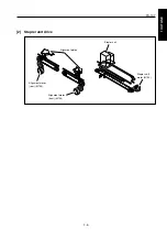
[2]

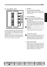
Stapler unit drive

Alignment plates

Alignment motor

(rear) (M703)

Alignment motor

(front) (M704)

Stapler unit

Stapler shift

motor (M705)

Summary of Contents for FS-107

Page 1: ...KONICA CORPORATION TECHNOLOGY SUPPORT CENTER TOKYO JAPAN SERVICE HANDBOOK FS 107 2001 02 Ver 3 0...

Page 2: ...CN26NF1780 KONICA CORPORATION COPYRIGHT 2001...

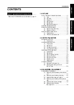
Page 3: ...sition 2 1 CONVEYANCE SECTION 2 2 1 Composition 2 2 2 Mechanisms 2 2 3 Conveyance control 2 3 4 Tray up down control 2 5 PAPER EXIT STAPLER UNIT 2 7 1 Composition 2 7 2 Mechanisms 2 7 3 Paper alignmen...

Page 4: ...Blank page 2 1 OUTLINE 2 UNIT EXPLANATION 3 DIS ASSEMBLY...

Page 5: ...1 OUTLINE 2 UNIT EXPLANATION 3 DIS ASSEMBLY OUTLINE 1...

Page 6: ...Blank page 2 1 OUTLINE 2 UNIT EXPLANATION 3 DIS ASSEMBLY...

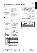
Page 7: ...rays 100 x 4 400 sheets Copy Paper weight 50 to 200g m2 papers Stack capacity 80g m2 high quality paper With 2 standard trays Non staple Staple Non staple Staple Special media 10 sheets 50 sheets Larg...

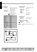
Page 8: ...1 x 17 8 5 x 11 8 5 x 14 8 5 x 11R 5 5 x 8 5 5 5 x 8 5R C mm 60 4 53 4 90 4 80 4 63 4 90 4 91 5 4 93 4 95 4 52 4 95 4 95 4 60 4 4 Machine data Power source DC24V 5V supplied from the main body Maximum...

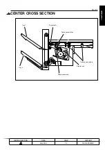
Page 9: ...TLINE 2 UNIT EXPLANATION 3 DIS ASSEMBLY CENTER CROSS SECTION Tray 1 Tray 2 Conveyance roller Conveyance rollers Conveyance belt Stapler unit Exit rolle A 1 METHOD REPLACEMENT PAGE 1 3 DATE May 2000 RE...

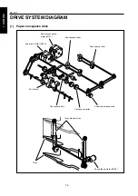
Page 10: ...Y DRIVE SYSTEM DIAGRAM 1 Paper conveyance drive Paper conveyance motor M701 Paper exit motor M702 Conveyance roller Exit roller A Conveyance belt Conveyance roller Paper jam release knob Tray up down...

Page 11: ...FS 107 1 5 1 OUTLINE 2 UNIT EXPLANATION 3 DIS ASSEMBLY 2 Stapler unit drive Alignment plates Alignment motor rear M703 Alignment motor front M704 Stapler unit Stapler shift motor M705...

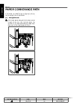
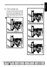
Page 12: ...ance paths are used changing by the mode selected 1 Straight mode In this mode paper conveyed to the finisher is exited straight into the tray For small size paper the operation of 2 Offset Mode Stapl...

Page 13: ...d once by the reverse rotation of the exit roller In the offset mode this stacked paper is offset by the paper alignment plates In the staple mode the paper is stapled When the respective process is f...

Page 14: ...Blank page 2 1 OUTLINE 2 UNIT EXPLANATION 3 DIS ASSEMBLY...

Page 15: ...1 1 OUTLINE 2 UNIT EXPLANATION 3 DIS ASSEMBLY UNIT EXPLANATION 2...

Page 16: ...Blank page 2 1 OUTLINE 2 UNIT EXPLANATION 3 DIS ASSEMBLY...

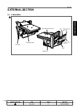
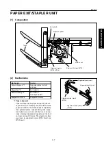
Page 17: ...TION 3 DIS ASSEMBLY EXTERNAL SECTION 1 Composition Tray 1 Optional tray 1 FT 107 Optional tray 2 FT 107 Tray 2 Paper conveyance cover Stapler unit Front door Conveyance door METHOD REPLACEMENT PAGE 2...

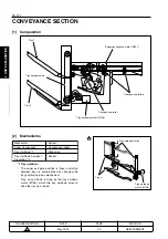
Page 18: ...Conveyance rollers Tray Up Down 1 Wire drive Tray Up Down Accident Shutter Prevention 2 1 Tray up down The paper exit gate position is fixed switching between trays is accomplished by changing the tr...

Page 19: ...ve force of the M701 paper conveyance motor which is transmitted to the conveyance rollers The M701 is linked with the main body so that rotation is set to low or high speed according to the conveyanc...

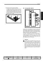
Page 20: ...24VDC is supplied to each load 5 S ACK MAIN BODY FS CB Transmission of OK signal from the main body to the finisher 6 M TXD MAIN BODY FS CB Serial data sign sending the movement condition of the main...

Page 21: ...t of the tray has been detected the machine judges that no optional trays are installed When PS716 is ON optional tray 1 is in place in this condition the M706 rotates normally raising the tray one st...

Page 22: ...nal L Top face H Not at top face 3 PS716 PS716 FS CB Tray installation detection signal L No tray H Tray in position 4 PS702 PS702 FS CB The power supply line for each load 24VDC is supplied to each l...

Page 23: ...pler Unit Shift 4 Stapler shift motor 1 Paper alignment Paper conveyed to the paper exit gate by the con veyance roller is stacked by reverse rotation of the paper exit roller A The stacked paper is a...

Page 24: ...gate by the conveyance rollers is then conveyed to the stack position by paper exit roller A running in reverse direction The conveyed paper is sent to the stopper by the friction of the conveyance b...

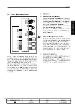
Page 25: ...ment operation The front and rear alignment plates work in symmetry to the front and rear based on the center of the alignment section alternately aligning and releasing To create this symmetrical mov...

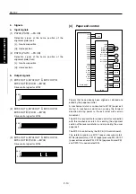
Page 26: ...CB M702 24VDC 24VDC M702 OUT A M702 OUT A M702 OUT B M702 OUT B 24VDC 24VDC 24VDC 5VDC 5VDC SGND SGND PGND PGND PGND SGND SGND M ACK SGND S REQ M RXD SGND S ACK M REQ SGND M TXD MAIN BODY M708 M708 DR...

Page 27: ...controlled by two signals which change the direction of the electrical current 2 M708 DRIVE 1 2 FS CB M708 M708 drive control signal The drive direction of the M708 is controlled by two signals which...

Page 28: ...PS716 is turned ON and then up until PS703 is turned ON set tray 1 at the paper exit position 2 Signal a Input signal 1 PS704 PS704 FS CB Paper full detection signal Goes H when paper full condition i...

Page 29: ...Y PS701 5VDC PS701 SGND PS708 5VDC PS708 SGND PS712 5VDC PS712 SGND PS713 5VDC PS713 SGND M707 DRIVE 1 M707 DRIVE 2 M708 M708 DRIVE 1 M708 DRIVE 2 FS CB In staple mode stapling is performed using the...

Page 30: ...05 moves the stapler unit for the second stapling operation After the copy is finished the stapler unit returns to its home position b No staple detection control The PS713 is equipped to detect the n...

Page 31: ...alignment plates front and rear 4 The paper exit gate shutter closes and the tray count operation takes place 2 Opening and closing motion of the front door 1 In case PS707 is ON it makes M702 go thro...

Page 32: ...Blank page 2 1 OUTLINE 2 UNIT EXPLANATION 3 DIS ASSEMBLY...

Page 33: ...1 OUTLINE 2 UNIT EXPLANATION 3 DIS ASSEMBLY DISASSEMBLY ASSEMBLY 3...

Page 34: ...y work 1 Be sure to unplug the power cord before working on the machine 2 Perform all reassembly work by reversing the order in which the component was disassembled unless otherwise specified 3 Do not...

Page 35: ...remove it 2 Removing and reinstalling of the tray 1 Take out each 3 sets of set screws and remove the cover s front and rear 2 Take out each 2 sets of set screws from the wire fittings on front and r...

Page 36: ...rizontal adjustment Set screws Lids Paper conveyance cover Set screws Plate spring rollers 3 Replacing the paper exit roller A 1 Remove the finisher from the main body 2 Take off 5 lids and 6 set scre...

Page 37: ...e E ring that affixes the belt gear slide the gear and remove the belt Caution Be careful to not drop the pin inside the gear E rings Shaft E rings Pin Paper exit roller A Pin 8 Remove the 5 E rings a...

Page 38: ...nger from the wire fitting Also check to see if the gear position at which the pulley is installed is in line with the opposite side rear Set screws Pulley tension plate Caution Ensure that the pulley...

Page 39: ...the side of the lower pulley rear 14 Attach the E ring and affix the lower pulley rear 15 Fasten the 2 set screws while pulling up the pulley tension plate rear applying 3kg tension Stapler unit Cart...

Page 40: ...the plate and remove Caution When reinstalling the plate be sure to insert the plate into the insides of the hooks 4 Take out the connector and 1 grounding screw from the stapler unit Stapler units Se...

Reviews: