background image

Field Service Ver. 1.0 Dec. 2008

5. Firmware upgrade

45

bizhub 362/282/222

MAINTENANCE

5.3

Firmware rewriting by the Internet ISW

5.3.1

Outline

• [Internet ISW] is the system which gives the instruction for updating the firmware with the 

CS Remote Care, so the main body will automatically receive the firmware from the pro-
gram server over a network for updating.

5.3.2

Service environment

The following conditions are necessary for using the Internet ISW function.
• The main body is connected to such a network environment that the firmware can be 

downloaded on the internet using the ftp protocol.

The “Internet ISW” will not operate under the following conditions.
• Main power switch is set to OFF.
• Sub power switch is set to OFF.
• The main body has the job currently performing.
• Modes other than normal mode are used.
• Machine has a paper jam.
• The version of firmware provided from the program server and MFBS board on the 

machine are not compatible with each other.

5.3.3

Preparations

• For details of each setting item, refer to ADJUSTMENT/SETTING “Internet ISW”.

See P.164

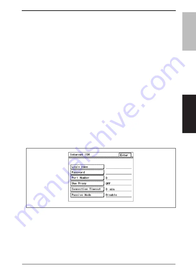
A. Internet ISW

1.

Call the Tech. Rep. Mode to the screen.

2.

Touch [Tech. Rep. Choice]

3.

Touch [Internet ISW]

4.

Touch [Login name], and enter the login name which is necessary for connecting to the 
program server on the on-screen keyboard, and touch [Enter].

5.

Touch [Password], and enter the password which is necessary for connecting to the 
program server on the on-screen keyboard, and touch [Enter].

6.

Touch [Port Number], and set the port number for the proxy server from 1 through 
65535.

7.

Touch [Use Proxy], for connecting via proxy server, select [Enter].

8.

Touch [Connection Timeout], set the time for the connection time out between 1 min 
and 60 min.

9.

Touch [Passive Mode] and, if connection through PASV (passive mode) is to be 
enabled, select [Enable].

A11UF3E501DA

Summary of Contents for Bizhub 222

Page 1: ...he is available only for North America This service manual is designed for copier with Firmware Ver 4040 0100 G20 44 00X and onward The is available only for North America This service manual is designed for copier with Firmware Ver 4040 0100 G20 44 00X and onward ...

Page 2: ...the service manual C 1 Notation of the service manual C 2 bizhub 362 282 222 Main body OUTLINE 1 MAINTENANCE 7 ADJUSTMENT SETTING 113 TROUBLESHOOTING 237 APPENDIX 291 Duplex Unit Switchback Unit OUTLINE 1 MAINTENANCE 3 ADJUSTMENT SETTING 7 Troubleshooting 11 Standard Controller OUTLINE 1 MAINTENANCE 3 TROUBLESHOOTING 5 FK 503 OUTLINE 1 MAINTENANCE 5 ADJUSTMENT SETTING 11 TROUBLESHOOTING 175 DF 620...

Page 3: ...USTMENT SETTING 17 TROUBLESHOOTING 25 JS 502 OUTLINE 1 MAINTENANCE 3 ADJUSTMENT SETTING 5 FS 530 PU 501 OT 602 OUTLINE 1 MAINTENANCE 5 ADJUSTMENT SETTING 23 TROUBLESHOOTING 35 MT 502 OUTLINE 1 MAINTENANCE 3 ADJUSTMENT SETTING 7 TROUBLESHOOTING 11 SD 507 OUTLINE 1 MAINTENANCE 3 ADJUSTMENT SETTING 29 TROUBLESHOOTING 37 ...

Page 4: ...rse of technical training and even after that for performing maintenance and control of the product properly Keep this Service Manual also for future service In this Service Manual each of three expressions DANGER WARNING and CAUTION is defined as follows together with a symbol mark to be used in a limited meaning When servicing the product the relevant works disassembling reassembling adjustment ...

Page 5: ...erformance and safety Such modifications are therefore strictly prohibited the points listed below are not exhaustive but they illustrate the reason ing behind this policy SAFETY WARNINGS Prohibited Actions DANGER Using any cables or power cord not specified by KMBT Using any fuse or thermostat not specified by KMBT Safety will not be assured leading to a risk of fire and injury Disabling fuse fun...

Page 6: ...cable having enough cur rent capacity and the cord set meets regulatory requirements for the area Use of inadequate cord set leads to fire or electric shock Attach power plug which meets the following criteria having configuration intended for the connection to wall outlet appropriate for the product s rated voltage and current and the plug has pin terminal s for grounding and meets regulatory req...

Page 7: ...er leads to the product connecting to inadequate power supply voltage current capacity grounding and may result in fire or electric shock If proper wall outlet is not available advice the customer to contact qualified electrician for the installation Plug the power cord into the dedicated wall outlet with a capacity greater than the maximum power consumption If excessive current flows in the wall ...

Page 8: ...o a risk of fire Check whether the power cord is damaged Check whether the sheath is damaged If the power plug cord or sheath is damaged replace with a new power cord with plug and connector on each end specified by KMBT Using the damaged power cord may result in fire or electric shock Do not bundle or tie the power cord Overheating may occur there leading to a risk of fire Check whether dust is c...

Page 9: ...not use an extension cable reel with the cable taken up Fire may result Prohibited Installation Places WARNING Do not place the product near flammable materials or vola tile materials that may catch fire A risk of fire exists Do not place the product in a place exposed to water such as rain A risk of fire and electric shock exists When not Using the Product for a long time WARNING When the product...

Page 10: ...ion before Servicing CAUTION Before conducting an inspection read all relevant docu mentation service manual technical notices etc and proceed with the inspection following the prescribed pro cedure using only the prescribed tools Do not make any adjustment not described in the documentation If the prescribed procedure or tool is not used the prod uct may break and a risk of injury or fire exists ...

Page 11: ... risk of elec tric shock exists Safety Checkpoints WARNING Check the exterior and frame for edges burrs and other damage The user or CE may be injured Do not allow any metal parts such as clips staples and screws to fall into the product They can short internal circuits and cause electric shock or fire Check wiring for squeezing and any other damage Current can leak leading to a risk of electric s...

Page 12: ...ng a lithium battery replace it with a new lith ium battery specified in the Parts Guide Manual Dispose of the used lithium battery using the method specified by local authority Improper replacement can cause explosion After replacing a part to which AC voltage is applied e g optical lamp and fixing lamp be sure to check the installa tion state A risk of fire exists Check the interlock switch and ...

Page 13: ... breathe excessive amounts or let the substances come into contact with eyes etc It may be stimulative If the substances get in the eye rinse with plenty of water immediately When symptoms are noticeable consult a physician Never throw the used cartridge and toner into fire You may be burned due to dust explosion Handling of Service Materials CAUTION Unplug the power cord from the wall outlet Drum...

Page 14: ...eaner at a time and take care not to spill any liquid If this happens immediately wipe it off A risk of fire exists When using any solvent ventilate the room well Breathing large quantities of organic solvents can lead to discomfort Handling of Service Materials CAUTION ...

Page 15: ...ar le constructeur Mettre au rebut les batteries usagées conformément aux instructions du fabricant Denmark ADVARSEL Lithiumbatteri Eksplosionsfare ved fejlagtig håndtering Udskiftning må kun ske med batteri af samme fabrikat og type Levér det brugte batteri tilbage til leverandøren Finland Sweden VAROlTUS Paristo voi räjähtää jos se on virheellisesti asennettu Vaihda paristo ainoastaan laitevalmi...

Page 16: ...ation Laser Aperture of the Print Head Unit This product employs a Class 3b laser diode that emits an invisible laser beam The laser diode and the scanning polygon mirror are incorporated in the print head unit The print head unit is NOT A FIELD SERVICE ITEM Therefore the print head unit should not be opened under any circumstances Semiconductor laser Maximum average radiation power 28 9 µW Wavele...

Page 17: ...s and must be attached to laser products marketed in the United States CAUTION Use of controls adjustments or performance of procedures other than those spec ified in this manual may result in hazardous radiation exposure All Areas CAUTION Use of controls adjustments or performance of procedures other than those spec ified in this manual may result in hazardous radiation exposure Denmark ADVARSEL ...

Page 18: ...aren utsättas för osynlig laserstrålning som överskrider gränsen för laser klass 1 VARNING Osynlig laserstrålning när denna del är öppnad och spärren är urkopplad Betrakta ej strålen Norway ADVERSEL Dersom apparatet brukes på annen måte enn spesifisert i denne bruksanvisning kan brukeren utsettes for unsynlig laserstråling som overskrider grensen for laser klass 1 LOUKAN 1 LASERLAITE KLASS 1 LASER...

Page 19: ... be used select ones with a lens conforming to the above specifications When a disassembly job needs to be performed in the laser beam path such as when working around the printerhead and PC Drum be sure first to turn the copier OFF If the job requires that the copier be left ON take off your watch and ring and wear laser protective goggles A highly reflective tool can be dangerous if it is brough...

Page 20: ...tion labels shown are attached in some areas on in the machine When accessing these areas for maintenance repair or adjustment special care should be taken to avoid burns and electric shock WARNING INDICATIONS ON THE MACHINE A11UP0C503DA CAUTION ...

Page 21: ...SAFETY AND IMPORTANT WARNING ITEMS S 18 A11UP0C504DA High voltage ...

Page 22: ...A High voltage You may be burned or injured if you touch any area that you are advised not to touch by any caution label Do not remove caution labels If any caution label has come off or soiled and therefore the caution cannot be read contact our Service Office ...

Page 23: ...of a serious accident has been received from a customer an on site evalua tion must be carried out quickly and KMBT must be notified 3 To determine the cause of the accident conditions and materials must be recorded through direct on site checks in accordance with instructions issued by KMBT 4 For reports and measures concerning serious accidents follow the regulations speci fied by every distribu...

Page 24: ...formation The basic configuration of each section is as follows However some options may not be applied to the following configuration Theory of Operation section Field service section OUTLINE Explanation of system configuration product specifications unit configuration and paper path COMPOSITION OPERATION Explanation of configuration of each unit operating system and control system OUTLINE Explan...

Page 25: ... the paper size No specific notation is added for the long edge feeding When the size has only the short edge feeding with no long edge feeding S will not be added to the paper size Sample notation 1 IC board Standard printer 2 bizhub 362 282 222 Main body 3 Microsoft Windows 98 Windows 98 Microsoft Windows Me Windows Me Microsoft Windows NT 4 0 Windows NT 4 0 or Windows NT Microsoft Windows 2000 ...

Page 26: ...SERVICE MANUAL 2008 12 Ver 1 0 FIELD SERVICE Main body ...

Page 27: ... represents the number of times the revision has been made To indicate clearly a section revised show in the lower outside section of the correspond ing page A number within represents the number of times the revision has been made NOTE Revision marks shown in a page are restricted only to the latest ones with the old ones deleted When a page revised in Ver 2 0 has been changed in Ver 3 0 The revi...

Page 28: ...ssy 19 3 4 3 Replacing the Tray 1 Feed Roller 20 3 4 4 Replacing the Tray 1 Pick up Roller 21 3 4 5 Replacing the Tray 1 Separation Roller Assy 23 3 4 6 Replacing the Tray 2 Feed Roller 25 3 4 7 Replacing the Tray 2 Pick up Roller 26 3 4 8 Replacing the Tray 2 Separation Roller 28 3 4 9 Replacing of the Registration Roller Bearings and Registration Roller Gears 1 2 30 3 4 10 Cleaning of the Paper ...

Page 29: ... Assembly Cleaning list Other parts 48 6 2 1 Disassembly Assembly parts list 48 6 2 2 Cleaning parts list 49 6 3 Disassembly Assembly procedure 50 6 3 1 IR Upper Left Cover Original Scanning Glass Front Holding Bracket Original Glass 50 6 3 2 Lower Rear Cover Lower Right Rear Cover Tray Rear Cover 50 6 3 3 Upper Rear Cover 51 6 3 4 Rear Right Cover Front Right Cover 51 6 3 5 IR Right Cover Rear Co...

Page 30: ... 6 3 31 Exposure Unit 79 6 3 32 Exposure Lamp 80 6 3 33 Scanner Drive Cables 81 6 3 34 Main Motor 86 6 3 35 IU Motor 86 6 3 36 Fusing Unit Cooling Fan Motor 87 6 3 37 Toner Suction Fan Motor 87 6 3 38 Temperature humidity Sensor 88 6 3 39 ATDC Sensor 88 6 3 40 Thermistor 90 6 3 41 Paper Exit Roll 1 92 6 3 42 Paper Exit Roll 2 92 6 3 43 Separation Claw 93 6 4 Cleaning procedure 95 6 4 1 Manual Bypa...

Page 31: ...ng Sensor Layout 109 6 7 2 Mounting of the Original Size Detecting Sensors Option 110 6 8 EEPROM 111 6 8 1 Remounting of the EEPROM 111 ADJUSTMENT SETTING 7 How to use the adjustment section 113 8 Utility Counter Mode 114 8 1 Utility Counter Mode function tree 114 8 2 Utility Counter Mode function setting procedure 118 8 2 1 Procedure 118 8 2 2 Exiting 118 8 2 3 Changing the setting value in Utili...

Page 32: ... MFP Set 148 8 7 2 Default Set 148 8 7 3 PDL Set 150 8 7 4 Test Print 151 8 8 Check Detail 151 9 Adjustment item list 152 10 Tech Rep Mode 154 10 1 Tech Rep Mode function setting procedure 154 10 2 Tech Rep Mode function tree 155 10 3 Settings in the Tech Rep Choice 157 10 3 1 System Set 157 10 3 2 Printer 159 10 3 3 Sheet through ADF 162 10 3 4 Center Erase Width 163 10 3 5 Country Set 163 10 3 6...

Page 33: ...0 6 9 Maintenance Counter 170 10 6 10 Fax Comm Error Counter 170 10 7 Settings in the Function 171 10 7 1 F1 171 10 7 2 F2 171 10 7 3 F7 1 171 10 7 4 F7 2 171 10 7 5 F8 171 10 7 6 F12 172 10 7 7 Hard Disk Format 172 10 7 8 FD 172 10 7 9 FC 173 10 7 10 Org Width Detect Adjust 173 10 7 11 Download Firmware 173 10 8 I O Check 174 10 8 1 Electrical Components Check Procedure Through Input Data Check 1...

Page 34: ... 1 2 Exiting 211 11 2 Service Security Mode Function Tree 211 11 3 Settings in the Service Security Mode 211 11 3 1 Service Code Change 211 12 Meter Count 212 12 1 Meter Count Function Setting Procedure 212 12 1 1 Procedure 212 12 1 2 Exiting 212 12 2 Meter Count Function Tree 212 12 3 Settings in the Meter Count 213 12 3 1 Management Function Choice 213 12 3 2 Counter Setting 215 13 Adjust Mode 2...

Page 35: ...d parts on PWBs 233 16 1 Test Print Switch S1 233 16 1 1 Procedure 233 16 2 Read white reference position adjustment 234 16 2 1 Jumper switch setting 234 16 3 Sub Power Switch SW49 235 16 4 Warm Restart Switch 235 16 4 1 Procedure 235 TROUBLESHOOTING 17 Jam Display 237 17 1 Misfeed Display 237 17 1 1 Misfeed Display Resetting Procedure 237 17 2 Sensor layout 238 17 2 1 System Mounted with PC 108 P...

Page 36: ...58 18 3 9 C2351 Toner Suction Fan Motor Failure 258 18 3 10 C2557 ATDC Sensor Failure 259 18 3 11 C255C ATDC Adjustment Failure 259 18 3 12 C2654 EEPROM Failure 259 18 3 13 C2702 Abnormal Image Transfer Voltage 259 18 3 14 C3451 Fusing Warm Up Failure Main 260 18 3 15 C3452 Fusing Warm Up Failure Sub 260 18 3 16 C3751 High Fuser Temperature Failure Main 260 18 3 17 C3752 High Fuser Temperature Fai...

Page 37: ...round 273 20 3 4 Scanner System Black streaks or bands 274 20 3 5 Scanner System Black spots 275 20 3 6 Scanner System White streaks or bands 276 20 3 7 Scanner System Uneven pitch 277 20 3 8 Printer System Blank copy or black copy 278 20 3 9 Printer System Low image density or rough image 279 20 3 10 Printer System Foggy background 280 20 3 11 Printer System Black streaks or bands 281 20 3 12 Pri...

Page 38: ... 300 22 8 FS 530 Option 301 22 9 PU 501 Option 302 22 10 MT 502 Option 303 22 11 SD 507 Option 304 23 Connector layout drawing 305 24 Timing chart 307 24 1 Main body 307 24 2 DF 620 308 24 2 1 1 Sided Mode A4 two sheets feeding 308 24 2 2 2 Sided Mode A4 two sheets feeding 309 24 2 3 Fax Fine mode A4 two sheets feeding 311 24 2 4 Fax real time transmission mode A4 two sheets feeding 312 ...

Page 39: ...bizhub 362 282 222 OUTLINE MAINTENANCE ADJUSTMENT SETTING TROUBLESHOOTING APPENDIX Field Service Ver 1 0 Dec 2008 xii Blank Page ...

Page 40: ...net PC 108 2 Stamp Unit SP 501 11 Desk DK 506 3 Reverse Automatic Document Feeder DF 620 12 Finisher FS 530 4 Data Controller D 103 13 Output Tray OT 602 5 Key Counter Kit 4 14 Saddle Sticher SD 507 6 Key Counter 1 15 Job Separator JS 502 7 Key Counter Mount Kit 2 16 Punch Unit PU 501 8 Paper Feed Cabinet PC 407 17 Mailbin Kit MT 502 9 Paper Feed Cabinet PC 206 A11UF1E500DA 1 3 2 8 10 9 11 15 12 1...

Page 41: ... However if the Fax Kit or the Scanner Unit is mounted the Expanded Memory unit is not necessary 3 Ones for Europe will be with the standard equipment 1 Machine 6 Scanner Unit SU 501 1 2 Fax Kit FK 503 7 Expanded Memory Unit EM 303 EM 304 EM 305 1 3 Fax Multi Line ML 502 8 Hard Disk HD 504 2 4 Local Interface kit EK 502 9 Security Kit SC 504 5 Dehumidifier Heater 1C 10 Mount Kit MK 709 3 A11UF1E50...

Page 42: ...ing System Separator fingers Fusing System Heat roller Types of Original Sheets books and three dimensional objects Max Original Size A3 or 11 17 Multiple Copies 1 to 999 Warming up Time 14 sec or less when the Auxiliary Power Switch is turned ON from a stabilized state in which the Main Power Switch is ON and Auxiliary Power Switch is OFF with the rated power source voltage and at a room temperat...

Page 43: ...m2 24 1 4 to 55 3 4 lb Postcards Envelopes Labels Thin Paper 50 to 55 g m2 13 1 4 to 14 3 4 lb Copy paper dimensions Max width length 297 to 420 mm 11 5 x 16 5 inches 297 to 432 mm 11 17 inches Min width length 148 to 210 mm 5 75 x 8 25 inches 90 to 140 mm 3 5 x 5 5 inches Power Requirements Voltage AC 120 V 220 240 V Frequency 50 60 Hz Max Power Consump tion 120 V 1380 W 10 200 V 1300 1470 W 10 D...

Page 44: ...r Driver PCL5e Emulation PCL6 XL Ver 2 1 Emulation PostScript3 Emulation 3011 xx xx Scan Driver TWAIN driver OS Compatibility Server Windows NT 4 0 Windows 2000 Service Pack 4 or later Windows Server 2003 or Windows Server 2008 Client Windows 2000 Windows XP Windows Vista or Windows NT 4 0 Mac OS 9 2 or later Mac OS X 10 2 Mac OS X 10 3 Mac OS X 10 4 Mac OS X 10 5 Interface Ethernet 10 Base T 100 ...

Page 45: ...2 Product specifications Field Service Ver 1 0 Dec 2008 6 bizhub 362 282 222 OUTLINE Blank Page ...

Page 46: ... personnel Check Clean Replace Lubri cation Descrip tions 1 Overall Paper take up and image conditions 2 Appearance 3 DF 620 Pick up Roller 2 4 Feed Roller 1 5 Separation Roller 1 6 Rollers and rolls 7 Scanning Guide 1 8 Reflective Sensor section 1 No Class Parts to be replaced Number of personnel Check Clean Replace Lubri cation Descrip tions 1 Overall Paper take up and image conditions 2 Appeara...

Page 47: ...aced Number of personnel Check Clean Replace Lubri cation Descrip tions 1 Overall Paper take up and image conditions 2 Appearance 3 DF 620 Pick up Roller 2 4 Feed Roller 1 5 Separation Roller 1 No Class Parts to be replaced Number of personnel Check Clean Replace Lubri cation Descrip tions 1 Overall Paper take up and image conditions 2 Appearance 3 Bypass Feed Roller 1 4 Separation Roller Assy 1 5...

Page 48: ...Main body 1 No Class Parts to be replaced Number of personnel Check Clean Replace Lubri cation Descrip tions 1 Overall Paper take up and image conditions 2 Appearance 3 Fusing section Fusing Unit 1 No Class Parts to be replaced Number of personnel Check Clean Replace Lubri cation Descrip tions 1 Overall Paper take up and image conditions 2 Appearance 3 Transport section Registration Roller Bearing...

Page 49: ...itions 2 Appearance 3 Processing section Photo Conductor Unit 1 4 Developer 1 5 Toner Filter Developing Unit 1 No Class Parts to be replaced Number of personnel Check Clean Replace Lubri cation Descrip tions 1 Overall Paper take up and image conditions 2 Appearance 3 Transport section Paper Dust Remover 1 4 Image Transfer Section Transfer Roller Unit 1 No Class Parts to be replaced Number of perso...

Page 50: ...ler 1 7 Separation Roller Assy 1 8 Tray 2 Feed Roller 1 9 Pick up Roller 1 10 Separation Roller Assy 1 11 PC 108 PC 206 PC 407 Pick up Roller 1 12 Feed Roller 1 13 Separation Roller Assy 1 14 FS 530 Rollers and rolls 15 MT 502 Rollers and rolls 16 SD 507 Rollers and rolls No Class Parts to be replaced Number of personnel Check Clean Replace Lubri cation Descrip tions 1 Overall Paper take up and im...

Page 51: ...ing Guide 1 8 Reflective Sensor section 1 No Class Parts to be replaced Number of personnel Check Clean Replace Lubri cation Descrip tions 1 Overall Paper take up and image conditions 2 Appearance 3 Processing section Photo Conductor Unit 1 4 Developer 1 5 Toner Filter Developing Unit 1 No Class Parts to be replaced Number of personnel Check Clean Replace Lubri cation Descrip tions 1 Overall Paper...

Page 52: ... replaced Number of personnel Check Clean Replace Lubri cation Descrip tions 1 Overall Paper take up and image conditions 2 Appearance 3 Bypass Feed Roller 1 4 Separation Roller Assy 1 5 Tray 1 Feed Roller 1 6 Pick up Roller 1 7 Separation Roller Assy 1 8 Tray 2 Feed Roller 1 9 Pick up Roller 1 10 Separation Roller Assy 1 11 PC 108 PC 206 PC 407 Pick up Roller 1 12 Feed Roller 1 13 Separation Roll...

Page 53: ... 6 Tray 2 Feed Roller 1 300 K 4030 3005 Replace those three parts at the same time P 25 7 Pick up Roller 1 300 K 4030 3005 P 26 8 Separation Roller Assy 1 300 K 4030 0151 P 28 9 Transport section Registration Roller Bearing 4 900 K 1164 3549 P 30 10 Registration Roller Gear 1 1 900 K 1164 3508 P 30 11 Registration Roller Gear 2 1 900 K 1164 3515 P 30 12 Paper Dust Remover 1 150 K 4040 0778 P 31 13...

Page 54: ... body bizhub 362 1 400 K 4040 2093 3 P 33 28 bizhub 282 1 320 K 4040 2093 29 bizhub 222 1 260 K 4040 2093 30 Ozone Filter 1 300 K 4011 2031 P 33 No Classification Parts name Qua ntity Actual durable cycle 1 Parts No Descriptions Ref Page in this manual 1 PC 108 PC 407 Pick up Roller 1 300 K 4030 3005 Replace those three parts at the same time 2 2 Feed Roller 1 300 K 4030 3005 3 Separation Roller A...

Page 55: ...anual 4 See MT 502 Service manual 5 See SD 507 Service manual No Classification Parts name Actual durable cycle 1 Descriptions Ref Page in this manual 1 DF 620 Pick up Roller 50 K 2 2 Feed Roller 50 K 3 Separation Roller 50 K 4 Misc rollers and rolls 50 K 5 Scanning Guide 50 K 6 Reflective Sensor section 50 K 7 FS 530 Rollers and rolls 300 K 3 8 MT 502 Rollers and rolls 300 K 4 9 SD 507 Rollers an...

Page 56: ... the machine operating conditions of each individual user Description Life value Specifica tion value Lift stop Photo Conductor Unit The distance through which the Photo Con ductor has been rotated is converted to a cor responding number of printed pages produced on A4 paper at 4P J and the life condition is detected when a predetermined value is reached 100 K 1 3 Not stopped 2 Developer Developin...

Page 57: ... Frame 2 3 Remove two screws 3 and the Feed Roller Cover 4 4 Snap off the C clip 5 for the Feed Roller and remove the bearing 6 5 Snap off the C clip 7 and remove the Bypass Feed Roller 8 6 To reinstall reverse the order of removal 7 Select Tech Rep Mode Counter Special Parts Counter Bypass and clear the counter NOTE Replace the Bypass Feed Roller and the Bypass Separation Roller Assy at the same ...

Page 58: ...Paper Separation Roller fix ing bracket Assy 2 3 Snap off the C clip 3 and remove the spring 4 and the guide plate 5 Remove the Bypass Paper Separa tion Roller Assy 6 4 To reinstall reverse the order of removal 5 Select Tech Rep Mode Counter Special Parts Counter Bypass and clear the counter NOTE Replace the Bypass Feed Roller and the Bypass Separation Roller Assy at the same time 2 1 4037F2C515DA...

Page 59: ... holding the stopper 2 remove Tray 1 3 2 Remove two screws 4 and the Con nector Cover 5 3 Remove the Connector 6 4 Remove two screws 7 and the Tray 1 Feed Roller Assy 8 5 Remove four screws 9 and the Tray 1 Feed Roller Assy Cover 10 and the Tray 1 Separator Roll Assy 11 A11UF2C500DA 1 2 3 A11UF2C501DA 5 4 A11UF2C502DA 8 7 6 4040F2C512DA 11 10 9 9 ...

Page 60: ...move the C clip 19 and the Tray 1 Feed Roller 20 9 To reinstall reverse the order of removal 10 Select Tech Rep Mode Counter Special Parts Counter Tray 1 and clear the counter 3 4 4 Replacing the Tray 1 Pick up Roller 1 Remove the screw 1 and holding the stopper 2 remove Tray 1 3 2 Remove two screws 4 and the Con nector Cover 5 4040F2C513DA 13 12 4040F2C514DA 15 14 16 18 17 4040F2C515DA 19 20 A11U...

Page 61: ...Roller Assy Cover 10 and the Tray 1 Separator Roll Assy 11 6 Remove two C clips 12 and two bearings 13 Then remove the Pick up Roller Assy 14 7 Remove one C clip 15 and the Tray 1 Pick up Roller 16 8 To reinstall reverse the order of removal 9 Select Tech Rep Mode Counter Special Parts Counter Tray 1 and clear the counter A11UF2C502DA 8 7 6 4040F2C512DA 11 10 9 9 4040F2C517DA 12 13 14 13 4040F2C51...

Page 62: ... 1 and holding the stopper 2 remove Tray 1 3 2 Remove two screws 4 and the Con nector Cover 5 3 Remove the Connector 6 4 Remove two screws 7 and the Tray 1 Feed Roller Assy 8 5 Remove four screws 9 and the Tray 1 Feed Roller Assy Cover 10 and the Tray 1 Separator Roll Assy 11 A11UF2C500DA 1 2 3 A11UF2C501DA 5 4 A11UF2C502DA 8 7 6 4040F2C512DA 11 10 9 9 ...

Page 63: ...lation plate 15 8 Remove the C clip 16 and the Tray 1 Separation Roller Assy 17 9 To reinstall reverse the order of removal 10 Select Tech Rep Mode Counter Special Parts Counter Tray 1 and clear the counter NOTE Install the Tray 1 Separation Roller Mounting Bracket Assy 18 while pressing the holder up so that it coheres to the metal bracket of the copier 4040F2C520DA 12 13 4040F2C521DA 14 14 15 40...

Page 64: ...ws 2 and the Transport Roller Cover 3 5 Remove two screws 4 and the Mis feed Clearing Cover 5 6 Unplug two connectors 6 7 Remove three screws 7 and the Tray 2 Feed Roller Assy 8 8 Remove four screws 9 and the C clip 10 Then remove the Tray 2 Feed Roller Cover 11 the Tray 2 Separation Roller Assy 12 and the Tray 2 Feed Roller Clutch 13 4040F2C524DA 1 4040F2C526DA 3 2 4040F2C527DA 5 4 4040F2C591DA 6...

Page 65: ... and the Tray 2 Feed Roller 22 12 To reinstall reverse the order of removal 13 Select Tech Rep Mode Counter Special Parts Counter Tray 2 and clear the counter 3 4 7 Replacing the Tray 2 Pick up Roller 1 Slide out the Tray 2 2 Remove the Multi Bypass Unit See P 72 3 Remove the Lower Right Cover 1 4 Remove two screws 2 and the Transport Roller Cover 3 4040F2C529DA 14 15 14 4040F2C530DA 17 16 18 20 1...

Page 66: ...y 2 Feed Roller Cover 11 the Tray 2 Separation Roller Assy 12 and the Tray 2 Feed Roller Clutch 13 9 Remove two C clips 14 and two bearings 15 Then remove the Tray 2 Pick up Roller Assy 16 10 Remove the C clip 17 and the Tray 2 Pick up Roller 18 11 To reinstall reverse the order of removal 12 Select Tech Rep Mode Counter Special Parts Counter Tray 2 and clear the counter 4040F2C527DA 5 4 4040F2C59...

Page 67: ...crews 2 and the Transport Roller Cover 3 5 Remove two screws 4 and the Mis feed Clearing Cover 5 6 Unplug two connectors 6 7 Remove three screws 7 and the Tray 2 Feed Roller Assy 8 8 Remove four screws 9 and the C clip 10 Then remove the Tray 2 Feed Roller Cover 11 the Tray 2 Separation Roller Assy 12 and the Tray 2 Feed Roller Clutch 13 4040F2C524DA 1 4040F2C526DA 3 2 4040F2C527DA 5 4 4040F2C591D...

Page 68: ...ation plate 17 11 Remove the C clip 18 and the Tray 2 Separation Roller Assy 19 12 To reinstall reverse the order of removal 13 Select Tech Rep Mode Counter Special Parts Counter Tray 2 and clear the counter NOTE Install the Tray 2 Separation Roller Mounting Bracket Assy 20 while pressing the holder up so that it coheres to the metal bracket of the copier 4040F2C536DA 14 15 4040F2C537DA 16 16 17 4...

Page 69: ...d Registration Roller Gears 2 4 3 Remove the screw 5 and the ground plate 6 CAUTION When reinstalling the ground plate make sure that the ground plate 7 is in contact with the side faces of the bushings 8 4 Remove the spring 9 and two Reg istration Roller Bearings 10 NOTE When reinstalling the bearings make sure that the flanges of the bearings are on the outside 4040F2C540DA 1 4040F2C544DA 2 3 4 ...

Page 70: ...he washer 14 and two wave washers 15 7 Remove the spring 16 two E rings 17 and two Registration Roller Bearings 18 NOTE When reinstalling the bearings make sure that the flanges of the bearings are on the outside 3 4 10 Cleaning of the Paper Dust Remover 1 Open the Right Door 1 2 Remove the Paper Dust Removal 2 4040F2C548DA 11 13 14 15 12 4040F2C549DA 16 17 18 4040F2C540DA 1 4040F2C541DA 2 ...

Page 71: ...3 4 11 Replacing of the Toner Filter Developing Unit 1 Open the Right Door 2 Remove the IU 1 3 Remove the Toner Filter Cover 2 4 Remove the Toner Filter Develop ing Unit 3 NOTE Replace the Photo Conductor Unit with a new one at the same time 4040F2C555DA 1 4040F2C655DA 2 4040F2C654DA 3 ...

Page 72: ...the tape portion 3 and peel off the Toner Filter Main body 4 NOTE When mounting the filter not the correct mounting position that is shown on the left Replace the Developing Unit with a new one at the same time 3 4 13 Replacement of the Ozone Filter 1 Remove the Upper Rear Cover See P 51 2 Remove the Rear Cover See P 52 3 Remove the Ozone Filter 1 4040F2C558DA 1 2 4040F2C557DA 4 3 4040F2C559DA 1 ...

Page 73: ...he PC Life counter before removing the IU After clearing the PC Life counter be sure to turn OFF the main power switch The Developer has to be replaced together with the Photo Conductor Unit 4 Open the Right Door 5 Remove the IU 1 6 Remove four screws silver 2 and disassemble the Photo Conductor Unit 3 and the Developing Unit 4 7 Remove three screws 5 and the Developer Scattering Prevention Plate ...

Page 74: ...llar is com pletely covered with the mylar sheet 9 11 Remove the developer 10 Removal of the Developer Dump the developer on the Sleeve Roller by rotating the gear in the direction of the arrow If you rotate the gear in reverse mylar for cleaning the ATDC Sen sor Dump developer until almost no developer sticks to the Sleeve Roller 4040F2C773DA 8 4040F2C772DA 9 9 Collar Collar 4040F2C581DB 10 4040F...

Page 75: ...ly Port 12 15 Using three screws 13 secure the Developer Scattering Prevention Plate 14 16 Install the four screws 15 to secure the New Photo Conductor Unit 16 and Developing Unit 17 17 Install the IU in the copier 18 Turn ON the main power switch 19 Select Tech Rep Mode Function F8 and press the Start key NOTE After replacing the developer be sure to execute F8 under Function of Tech Rep Mode Whe...

Page 76: ...ever that the thermistor and several other parts mentioned in this machine may be replaced as an individual part with a new one 1 Open the Right Door 2 Remove the Rear Right Cover See P 51 3 Remove the screw 1 and the Front Right Cover 2 4 Unplug two connectors 3 of the Switch Back Unit 5 Loosen the screw 4 in front 6 Remove the screw 5 in front 7 Loosen the screw 6 in the back 8 Remove the screw ...

Page 77: ...d the Con nector Cover 10 11 Remove two screws 11 and unplug three connectors 12 Then remove the Fusing Unit 13 3 5 2 Replacement of the Transfer Roller Unit 1 Open the Right Door 2 Pull down the knobs 1 forward and remove the Transfer Roller 2 4040F2C658DA 9 10 4040F2C566DA 11 12 12 12 13 4040F2C554DA 2 1 1 ...

Page 78: ...r with the Developing Unit 4 Open the Right Door 5 Remove the IU 1 6 Remove four screws silver 2 and disassemble the Photo Conductor Unit 3 and the Developing Unit 4 7 Replace the Developing Unit 4 8 Supply new developer to the new Developing Unit See P 34 9 Install the four screws 5 to secure the Photo Conductor Unit 6 and Developing Unit 7 10 Install the IU in the copier 11 Turn ON the main powe...

Page 79: ...vice tool Field Service Ver 1 0 Dec 2008 40 bizhub 362 282 222 MAINTENANCE 4 Service tool 4 1 CE Tool list Tool name Shape Personnel Parts No Remarks Thermistor Holding Check Jig 1 4040 7901 01 4040F2C728DA ...

Page 80: ...es to be upgraded to the compact flash If wrong firmware is copied no control panel display is given and thus no firmware can be downloaded 5 1 3 Checking ROM version Before attempting to upgrade the firmware check the current ROM version See P 210 5 2 Firmware rewriting by the compact flash NOTE NEVER attempt to remove or insert the compact flash with the machine power turned ON 5 2 1 MSC 1 Turn ...

Page 81: ... When the upgrading sequence is completed which is notified by the message FINISH appearing on the screen turn OFF the main power switch NOTE NEVER turn OFF the main power switch until the message FINISH appears on the screen 7 Remove the Compact flash card 2 from the slot 8 Turn ON the main power switch 9 Call the Tech Rep Mode to the screen See P 154 10 Select ROM Version 11 Make sure if the ver...

Page 82: ... the compact flash card are those of either the engine or Fin isher or wrong no screen display is given and thus no firmware can be down loaded 1 Turn OFF the main power switch 2 Remove the Compact flash Cover 1 3 Insert the compact flash card 2 to which the engine upgrading files have been copied into the slot 4 Open the Right Door NOTE Be sure to open the Right Door before turning ON the main po...

Page 83: ...r 5 to 6 min During this period NEVER turn off the machine power If the Finisher firmware is also upgraded the entire sequence will take about 10 to 11 min 12 When the upgrading sequence is completed turn OFF the main power switch 13 Remove the compact flash card 2 from the slot After some while there after turn ON the main power switch 14 Call the Tech Rep Mode to the screen See P 154 15 Select R...

Page 84: ...ode are used Machine has a paper jam The version of firmware provided from the program server and MFBS board on the machine are not compatible with each other 5 3 3 Preparations For details of each setting item refer to ADJUSTMENT SETTING Internet ISW See P 164 A Internet ISW 1 Call the Tech Rep Mode to the screen 2 Touch Tech Rep Choice 3 Touch Internet ISW 4 Touch Login name and enter the login ...

Page 85: ...te Care refer to CS Remote Care Center Manual For detailed error information relating to CS Remote Care refer to ADJUSTMENT SET TING CS Remote Care See P 205 NOTE Before updating firmware using Internet ISW contact the dministrator to get agreement Do not update firmware via Internet ISW when a job is processed Internet ISW does not function when a job is processed ...

Page 86: ...o or more screws are used for a single part only one repre sentative screw may be marked with the red paint C Variable Resistors on Board NOTE Do not turn the variable resistors on boards for which no adjusting instructions are given in Adjustment Setting D Removal of PWBs CAUTION When removing a circuit board or other electrical component refer to SAFETY AND IMPORTANT WARNING ITEMS and follow the...

Page 87: ...P 55 12 Rear Left Cover P 55 13 Front Right Cover P 51 14 Rear Right Cover P 51 15 Lower Right Rear Cover P 50 16 Lower Right Cover P 56 17 Rear Cover P 52 18 Upper Rear Cover P 51 19 Lower Rear Cover P 50 20 Tray 1 P 57 21 Tray 2 P 58 22 Tray Rear Cover P 50 23 Front Manual Bypass Cover P 56 24 Rear Manual Bypass Cover P 56 25 IR Right Cover P 52 26 IR Left Cover P 55 27 IR Upper Left Cover P 50 ...

Page 88: ...idity Sensor P 88 53 ATDC Sensor P 88 54 Fusing Unit Thermistor P 90 55 Paper Exit Roll 1 P 92 56 Paper Exit Roll 2 P 92 57 Separation Claw P 93 No Section Part name Ref Page No Section Part name Ref Page 1 Bypass Feed Roller P 95 2 Separation Roller P 95 3 Tray1 Feed Roller P 96 4 Pick up Roller P 97 5 Separation Roller P 98 6 Tray 2 Feed Roller P 99 7 Pick up Roller P 99 8 Separation Roller P 10...

Page 89: ...and remove the IR Upper Left Cover 2 2 Remove the Original Scanning Glass 3 3 Remove two Screws 4 and remove the Front Holding Bracket 5 4 Remove two Screws 6 and remove the Original Glass 7 6 3 2 Lower Rear Cover Lower Right Rear Cover Tray Rear Cover 1 Remove four Screws 1 and remove the Lower Rear Cover 2 2 Remove two Screws 3 and remove the Lower Right Rear Cover 4 A11UF2C504DA 4 5 7 6 3 2 1 A...

Page 90: ...r is installed at the correct position 6 3 3 Upper Rear Cover 1 Remove three screws 1 and push ing down the actuator 2 remove the Upper Rear Cover 3 6 3 4 Rear Right Cover Front Right Cover 1 Open the Right Door 2 Remove two Screws 1 and remove the Rear Right Cover 2 3 Remove the Screws 3 and remove the Front Right Cover 4 4040F2C660DA 6 5 7 A11UF2C506DA 1 2 3 A11UF2C507DA 1 2 3 4 ...

Page 91: ... Rear Cover 1 Open the Right Door 2 Remove the Upper Rear Cover See P 51 3 Remove the IR Right Cover 1 4 Remove thirteen Screws 2 and remove the Rear Cover 3 6 3 6 Front Door 1 Open the Front Door 1 2 Remove the screw 2 C clip 3 and the Front Door 1 A11UF2C508DA 3 2 2 2 1 2 2 A11UF2C509DA 1 3 2 ...

Page 92: ... Front Cover 1 Open the Front Door 1 2 Remove three screws 2 and the Paper Output Cover 3 3 Slide out the Tray 1 4 Remove two screws 4 and the Con nector Cover 5 5 Remove the Front Door See P 52 6 Remove five screws 6 and the Lower Front Cover 7 A11UF2C510DA 2 1 2 3 A11UF2C511DA 4 5 A11UF2C512DA 6 7 6 6 ...

Page 93: ...ight Door 2 Remove the Front Right Cover See P 51 3 Remove the screw 1 and the Upper Front Cover 2 4 Remove three screws 3 and the Middle Front Cover 4 5 Remove the Toner Hopper Unit See P 75 6 Remove the Paper Output Cover See P 53 7 Remove the Front Door See P 52 8 Remove the Lower Front Cover See P 53 A11UF2C513DA 1 2 A11UF2C515DA 4 3 3 ...

Page 94: ...3 9 IR Left Cover Rear Left Cover Left Cover 1 Remove the Upper Rear Cover See P 51 2 Remove the IR Left Cover 1 3 Remove two screws 2 and the Rear Left Cover 3 4 Remove the Rear Cover See P 52 5 Remove the Paper Output Cover See P 53 6 Remove three screws 4 and the Left Cover 5 A11UF2C514DA 3 4 3 A11UF2C516DA 5 3 4 2 1 ...

Page 95: ...l Bypass Cover Front Manual Bypass Cover Lower Right Cover 1 Remove two screws 1 and the Rear Manual Bypass Cover 2 2 Remove the screw 3 and the Front Manual Bypass Cover 4 3 Remove the Manual Bypass Unit See P 72 4 Remove two tabs 5 and the Lower Right Door Cover 6 A11UF2C517DA 1 2 5 6 3 4 ...

Page 96: ...screw covers 1 2 Remove the four screws 2 on the sides of the Control Panel 3 Disconnect the connector 3 and remove the Control Panel 4 6 3 12 Tray 1 1 Slide out the Tray 1 3 2 Remove the screw 1 and holding the stopper 2 remove the Tray 1 3 4040F2C592DA 1 4040F2C593DA 2 2 4040F2C594DA 3 4 A11UF2C500DA 1 2 3 ...

Page 97: ...ve the Rear Cover See P 52 3 Remove five screws 1 and the Mechanical Control Board Cover 2 4 Unplug the all connectors 5 Remove five screws 3 and the Mechanical Control Board 4 NOTE When replacing the Mechanical Control Board be sure to replace the EEPROM See P 111 When the Mechanical Control Board has been replaced with a new one check the ROM version and upgrade the firmware to the latest versio...

Page 98: ... Rear Cover See P 52 3 Remove five screws 1 and the Mechanical Control Board Cover 2 4 Remove the Tray 1 See P 57 5 Disconnect two connectors PJ23 PJ24 3 from the Mechanical Con trol Board 6 Remove two screws 4 and the Lift Up Assy 5 7 Remove four tabs 6 and the FD Paper Size Board Assy 7 4040F2C561DA 2 1 4040F2C656DA 3 4040F2C573DA 5 4 4040F2C572DA 6 7 ...

Page 99: ...ws 1 and the Mechanical Control Board Cover 2 4 Remove the Tray Rear Cover See P 50 5 Remove the Lower Rear Cover See P 50 6 Remove the Tray 2 See P 58 7 Disconnect two connectors PJ25 PJ26 3 from the Mechanical Con trol Board 8 Remove two screws 4 and the Lift Up Assy 5 9 Remove four tabs 6 and the FD Paper Size Board Assy 7 4040F2C561DA 2 1 4040F2C657DA 3 4040F2C571DA 5 4 4040F2C572DA 6 7 ...

Page 100: ...2 4 Remove the Rear Left Cover See P 55 5 Remove the Left Cover See P 55 6 Remove seven screws 1 and the Power Supply Unit Cover 2 7 Remove two screws 3 and the Power Supply Cooling Fan Motor 4 8 Unplug seven connectors 6 and remove three screws 5 and the Power Supply Unit Assy 7 CAUTION At reinstallation make sure that the harness is not slack 4040F2C599DA 1 1 2 1 4040F2C601DA 4 3 4040F2C602DA 6 ...

Page 101: ...e Rear Cover See P 52 5 Remove the Toner Suction Fan Motor See P 87 6 Remove the screw 1 and unhook two tabs 2 on the rear side surface Then remove the Toner Suction Duct 3 7 Unplug the connector 4 and remove two screws 5 and the High Voltage Unit Cover 6 8 Unplug four connectors 7 and remove two screws 8 and the High Voltage Unit 9 4040F2C672DA 1 2 3 4040F2C609DA 6 5 4 4040F2C610DA 7 8 7 7 7 9 ...

Page 102: ... mounted discon nect the two connectors CN7 1 CN6 2 4 Remove three screws 3 and the MFBS Board Assy 4 5 Remove five screws 5 and the MFBS Board mounting bracket 6 NOTE Remove the Hard Disk if one is mounted 6 Remove the stopper RAMS Board 7 and MEMS Board 8 7 Remove the MFBS Board 9 NOTE Remove the MEM Board 10 if mounted in the expansion slot 4040F2C693DA 2 1 4040F2C694DA 3 4 4040F2C751DA 5 5 6 4...

Page 103: ...INTENANCE 6 3 20 Inverter Board 1 Remove the IR Upper Left Cover See P 50 2 Remove the Front Holding Bracket See P 50 3 Remove the Original Glass See P 50 4 Disconnect the connector 1 and remove the flat cable 2 screw 3 and the Inverter Board 4 4040F2C695DA 1 3 2 4 ...

Page 104: ... the IR Upper Left Cover See P 50 3 Remove the Front Holding Bracket See P 50 4 Remove the Original Glass See P 50 5 Remove four screws 1 flat cable 2 and the BCRS Board cover 3 6 Unplug eight connectors 4 7 Remove three screws 5 disconnect the connector 6 and remove the BCRS Board 7 4040F2C696DA 3 2 1 4040F2C697DA 4 4 4040F2C698DA 5 6 7 ...

Page 105: ...screws 5 and two flat springs 6 Then remove the CCD Unit 7 NOTE When the CCD Unit has been replaced with a new one make the installation adjustment that must be made when the CCD Unit is replaced See P 66 B Installation Adjustment to be Made when CCD Unit is Replaced NOTE Make this adjustment only when the CCD Unit has been replaced with a new one Before attempting to make this adjustment make sur...

Page 106: ...ed through the subsequent procedures and there is no need to tighten the screws of the Original Glass Front Holding Bracket and IR Upper Left Cover 7 Turn ON the main power switch 8 If the setting in Scanner Registration or Scanner Zoom Adjust available from the Adjust mode has been changed set the function to 0 zero or 1 000 zoom ratio 9 Prepare a test chart as shown on the left and make a copy o...

Page 107: ...Deviation Adjustment Procedure Using Screws A and B If tilt or deviation in the FD direction is as shown on the left A Using an Allen wrench 3 mm turn screw A counterclockwise B Using an Allen wrench 3 mm turn screw B clockwise 1 4 turn of the screw results in deviation of 1 mm If tilt or deviation in the FD direction is as shown on the left A Using an Allen wrench 3 mm turn screw A counterclockwi...

Page 108: ...that have been removed CD Deviation Adjustment Procedure Using Adjustment Plate E If deviation in the CD direction is as shown on the left 1 Using a flat blade screwdriver turn adjustment plate E counterclock wise 2 Tighten screws C and D If deviation in the CD direction is as shown on the left 1 Using a flat blade screwdriver turn adjustment plate E clockwise 2 Tighten screws C and D 4030D597AA A...

Page 109: ...nect two connectors 1 and remove three flat cables 2 3 Remove two screws 3 and the Operation Board 1 4 4 Remove two screws 5 and the Bracket 6 5 Remove ten screws 7 and the Operation Key Board 1 8 6 Remove two screws 9 connector 10 and the Operation Key Board 2 11 4040F2C758DA 2 3 1 3 4 4040F2C759DA 5 6 4040F2C760DA 7 7 8 4040F2C761DA 9 10 11 ...

Page 110: ...e the screw 12 two connec tors 13 and the Operation Board 2 14 8 Remove two screws 15 and the Bracket 16 9 Remove two screws 17 and the LCD Board Cover 18 10 Remove four screws 19 and the LCD Board 20 4040F2C762DA 13 14 12 13 4040F2C763DA 15 16 4040F2C764DA 17 18 4040F2C765DA 19 20 ...

Page 111: ...ct the three con nectors 3 and remove the Manual Bypass Unit 4 NOTE When the Manual Bypass Unit has been mounted be sure to perform the Manual Bypass Unit Installation Check procedures See P 230 6 3 25 PH Unit 1 Remove the Upper Rear Cover See P 51 2 Remove the Rear Cover See P 52 3 Open the Front Door 4 Remove the Paper Output Cover See P 53 5 Remove nine screws 1 and the PH protective metal brac...

Page 112: ...ness protective metal brackets 6 8 Remove the harness from the cord holder 9 Remove five screws 7 and the Mechanical Control Board Cover 8 10 Remove two flat cables PJ3 PJ35 9 11 Remove three screws 10 and the PH Unit 11 4040F2C613DA 5 6 5 6 5 4040F2C614DA 4040F2C615DA 8 7 4040F2C674DA 9 4040F2C616DA 11 10 10 ...

Page 113: ...ffixed to the PH Spacers Used Should be screw installation position Screw Position PH label color A B C Green label No spacer No spacer No spacer Blue label No spacer 0 1 mm spacer 0 2 mm spacer Yellow label 0 2 mm spacer 0 1 mm spacer No spacer Part No Spacer Color 0 1 mm spacer 4030 2053 01 Black 0 2 mm spacer 4030 2054 01 White 4040F2C659DA A C B ...

Page 114: ...ont Door See P 52 3 Remove the Paper Output Cover See P 53 4 Open the Right Door 5 Remove the Front Cover See P 54 6 Remove the Lower Front Cover See P 53 7 Remove five screws 1 and the toner hopper protective metal bracket 2 8 Remove the screw 3 and the Toner Hopper Unit 4 9 Close the right door and remove the pressure spring 5 NOTE Make sure that the right door is kept closed 4040F2C568DA 1 2 40...

Page 115: ...etal bracket 7 11 Unplug two connectors 8 and remove four screws 9 and the Toner Hopper Assy 10 12 Remove the two screws 11 and dis connect the connector 12 from the rear side surface 13 Remove two screws 13 and the Toner Replenishing Drive Unit 14 4040F2C606DA 6 6 7 4040F2C607DA 9 8 9 9 8 10 4040F2C673DA 11 12 4040F2C624DA 13 14 ...

Page 116: ...he connector 1 and remove the screw 2 and ground wire 3 3 Remove four screws 4 and the Duplex Unit 5 6 3 29 Switch Back Unit 1 Open the Right Door 2 Remove the Rear Right Cover See P 51 3 Remove the screw 1 and the Front Right Cover 2 4 Unplug two connectors 3 of the Switch Back Unit 4040F2C569DA 2 1 3 4040F2C570DA 4 5 4040F2C560DA 2 1 4040F2C563DA 3 ...

Page 117: ... back 8 Remove the screw 7 in the back 9 Remove the Switch Back Unit 8 10 Remove two screws 9 and the lower Switch Back Unit 10 6 3 30 Scanner Motor 1 Remove the Upper Rear Cover See P 51 2 Remove the IR Right Cover See P 52 3 Remove ten wiring saddles 1 and disconnect the connector 2 4040F2C564DA 4 5 6 7 4040F2C565DA 8 4040F2C567DA 10 9 4040F2C699DA 1 1 1 1 2 ...

Page 118: ...racket See P 50 3 Remove the Original Glass See P 50 4 Slide the Exposure Unit 1 to the removal position 5 Remove two screws 2 6 Remove the screw 3 and the flat cable 4 7 Remove the flat cable 5 and the Exposure Unit 6 8 To reinstall reverse the order of removal NOTE If the Exposure Unit has been removed be sure to make the Scan ner positioning adjustment See P 228 4040F2C690DA 3 4 5 4040F2C700DA ...

Page 119: ...emove the Original Glass See P 50 4 Move the Exposure Unit 1 to the removal position 5 Disconnect the connector 2 and remove the Exposure Lamp harness 3 Reinstall the Exposure Lamp harness as follows 6 Remove the screw 4 7 Slide the Exposure Lamp 5 to the front and pull it off the holder 6 4040F2C705DA 1 4040F2C709DA 2 3 4040F2C706DA Back View Side View Front View 4040F2C710DA 4 6 5 ...

Page 120: ... 4 Remove the Original Glass See P 50 5 Remove the Exposure Unit See P 79 6 Remove the Scanner Motor See P 78 7 Remove six screws 1 and the Origi nal Cover hinge support 2 8 Remove the screw 3 and the Scan ner Drive Gear 4 from the shaft 9 Remove two screws 5 and the front and rear pulleys 10 Remove the bearing 6 and shaft 7 11 Remove the Scanner Drive Cables from each hook 4040F2C707DA 1 1 2 4040...

Page 121: ...turns counter clockwise from the rear toward the front side NOTE Make sure that no part of the cable rides on the other 3 Wind Scanner Drive Cable 2 4 four turns clockwise from the front to the rear side Then secure the cable with tape NOTE Make sure that no part of the cable rides on the other 4040F2C714DA Pulley A Pulley B Pulley C Pulley D Pulley E Pulley G Pulley F Pulley H Scanner Drive Cable...

Page 122: ...m the rear toward the front side NOTE Make sure that no part of the cable rides on the other 6 Wind Scanner Drive Cable 4 8 four turns clockwise from the rear to the front side Then secure the cable with tape NOTE Make sure that no part of the cable rides on the other 7 Install two pulleys front and rear 9 to the shaft 8 Attach two bushings 10 to the shaft 9 Secure the front and rear pulleys 11 us...

Page 123: ...lley B 15 hook the fixing bead to the fixing spring 16 and then hook the spring to the catch 17 in the frame 13 Wind Scanner Drive Cable 1 around pulley A 18 and pulley C 19 and hook the bead to the side surface 20 of the Scanner Frame Rear 14 Wind Scanner Drive Cable 4 around pulley E 21 and pulley G 22 and hook the fixing bead to the fixing spring 23 and then hook the spring to the catch 24 in t...

Page 124: ... Scanner Drive Cable 3 around pulley H 25 and pulley F 26 and hook the bead to the side surface 27 of the Scanner Frame 16 Remove the pulley tape 17 Mount the cable to the Exposure Unit 28 18 Readjust the position of the Exposure Unit See P 228 4040F2C726DA 25 27 26 4040F2C727DA 28 ...

Page 125: ... Rear Right Cover See P 51 4 Remove two screws 1 and the Ozone Filter Assy 2 5 Remove four screws 3 disconnect the connector 4 and remove the Main Motor 5 6 3 35 IU Motor 1 Remove the Upper Rear Cover See P 51 2 Remove the Rear Cover See P 52 3 Remove four screws 1 disconnect the connector 2 and remove the IU Motor 3 4040F2C617DA 1 2 4040F2C618DA 3 3 4 5 4040F2C619DA 1 1 2 3 ...

Page 126: ...e wiring saddles 1 and disconnect the connector PJ33 2 4 Remove two screws 3 and the Fus ing Unit Cooling Fan Motor 4 6 3 37 Toner Suction Fan Motor 1 Remove the Upper Rear Cover See P 51 2 Remove the Rear Cover See P 52 3 Remove two screws 1 and two wir ing saddles 2 disconnect the con nector 3 and remove the Toner Suction Fan Motor 4 4040F2C622DA 1 2 4040F2C623DA 3 4 3 4040F2C621DA 1 4 1 3 2 ...

Page 127: ...p Mode Counter Special Parts Counter Developer and clear the counter 2 Turn OFF the main power switch NOTE Clear the counter before removing the IU After clearing the counter be sure to turn OFF the Main Power Switch 3 Open the Right Door 4 Remove the Imaging Unit 1 5 Remove four screws silver 2 and disassemble the Photo Conductor Unit 3 and the Developing Unit 4 6 Remove three screws 5 and the De...

Page 128: ...he gear in the direction of the arrow If you rotate the gear in reverse mylar for cleaning the ATDC Sensor Dump developer until almost no developer sticks to the Sleeve Roller 9 Remove two screws 9 and open the Cover 10 10 Remove two screws 11 disconnect the connector 12 and remove the ATDC Sensor 13 11 Add developer See P 34 4040F2C580DA 7 4040F2C581DA 8 4040F2C582DA 4040F2C745DA 9 10 4040F2C746D...

Page 129: ... off the C clip 1 and remove the Fusing Entrance Guide Plate 2 3 Remove two shoulder screws 3 the screw 4 and the Exit Rolls 2 Assy 5 4 Remove two wiring saddles 6 and the harness 5 Disconnect the connector 7 of the Exit Sensor and remove the Exit Rolls 2 Assy 8 4040F2C625DA 2 1 4040F2C643DA 3 4 5 3 4040F2C730DA 6 4040F2C431DA 7 8 ...

Page 130: ... the bracket that supports the thermistor and the jig 7 Remove two screws 10 the Fusing Roller Thermistor 11 and Fusing Roller Sub Thermistor 12 Precautions for mounting the ther mistors When reinstalling the thermistors use the Thermistor Holding Check Jig After installation use the jig to make sure that the bracket is not bent 4040F2E753DA 9 9 Bracket Fusing Roller Sub Thermistor side Fusing Rol...

Page 131: ...e four screws 1 and four Exit Rolls 1 Assy 2 3 Remove the Exit Roll 1 3 6 3 42 Paper Exit Roll 2 1 Remove the Fusing Unit See P 37 2 Snap off the C clip 1 and remove the Fusing Entrance Guide Plate 2 3 Remove two shoulder screws 3 the screw 4 and the Exit Rolls 2 Assy 5 4040F2C641DA 1 2 4040F2C642DA 3 4040F2C625DA 2 1 4040F2C643DA 3 4 5 3 ...

Page 132: ...7 of the Exit Sensor and remove the Exit Rolls 2 Assy 8 6 Remove the screw 9 and the Sepa ration Claw Assy 10 7 Remove four Exit Rolls 2 11 6 3 43 Separation Claw 1 Remove the Fusing Unit See P 37 2 Snap off the C clip 1 and remove the Fusing Entrance Guide Plate 2 4040F2C730DA 6 4040F2C431DA 7 8 4040F2C644DA 9 10 4040F2C645DA 11 4040F2C625DA 2 1 ...

Page 133: ...5 4 Remove two wiring saddles 6 and the harness 5 Disconnect the connector 7 of the Exit Sensor and remove the Exit Rolls 2 Assy 8 6 Remove the screw 9 and the Sepa ration Claw Assy 10 7 Remove five springs 11 the shaft 12 and five Separation Claws 13 4040F2C643DA 3 4 5 3 4040F2C730DA 6 4040F2C431DA 7 8 4040F2C644DA 9 10 4040F2C747DA 11 13 12 ...

Page 134: ...s 1 and the Man ual Bypass Separation Fixing Bracket Assy 2 3 Using a soft cloth dampened with alcohol wipe the Manual Bypass Feed Roller 3 clean of dirt 6 4 2 Manual Bypass Separation Roller 1 Remove the Manual Bypass Unit See P 72 2 Remove two screws 1 and the Man ual Bypass Separation Fixing Bracket Assy 2 3 Using a soft cloth dampened with alcohol wipe the Manual Bypass Separation Roller 3 cle...

Page 135: ...lding the stopper 2 remove the Tray 1 3 2 Remove two screws 4 and the Con nector Cover 5 3 Unplug the connector 6 4 Remove two screws 7 and the Tray 1 Feed Roller Assy 8 5 Using a soft cloth dampened with alcohol wipe the Tray 1 Feed Roller 9 clean of dirt A11UF2C500DA 1 2 3 A11UF2C501DA 5 4 A11UF2C502DA 8 7 6 4040F2C511DA 9 ...

Page 136: ...lding the stopper 2 remove the Tray 1 3 2 Remove two screws 4 and the Con nector Cover 5 3 Remove the connector 6 4 Remove two screws 7 and the Tray 1 Feed Roller Assy 8 5 Using a soft cloth dampened with alcohol wipe the Tray 1 Pick up Roller 9 clean of dirt A11UF2C500DA 1 2 3 A11UF2C501DA 5 4 A11UF2C502DA 8 7 6 4040F2C516DA 9 ...

Page 137: ...lding the stopper 2 remove the Tray 1 3 2 Remove two screws 4 and the Con nector Cover 5 3 Remove the connector 6 4 Remove two screws 7 and the Tray 1 Feed Roller Assy 8 5 Using a soft cloth dampened with alcohol wipe the Tray 1 Separation Roller 9 clean of dirt A11UF2C500DA 1 2 3 A11UF2C501DA 5 4 A11UF2C502DA 8 7 6 4040F2C519DA 9 ...

Page 138: ...wer Right Cover 1 4 Remove two connectors 2 5 Remove three screws 3 and the Tray 2 Feed Roller Assy 4 6 Using a soft cloth dampened with alcohol wipe the Tray 2 Feed Roller 5 clean of dirt 6 4 7 Tray 2 Pick up Roller 1 Slide out the Tray 2 2 Remove the Manual Bypass Unit See P 72 3 Remove the Lower Right Cover 1 4040F2C524DA 1 4040F2C595DA 2 3 3 4 4040F2C525DA 5 4040F2C524DA 1 ...

Page 139: ...ck up Roller 5 clean of dirt 6 4 8 Tray 2 Separation Roller 1 Slide out the Tray 2 2 Remove the Manual Bypass Unit See P 72 3 Remove the Lower Right Cover 1 4 Remove two connectors 2 5 Remove three screws 3 and the Tray 2 Feed Roller Assy 4 6 Using a soft cloth dampened with alcohol wipe the Tray 2 Separation Roller 5 clean of dirt 4040F2C595DA 2 3 3 4 4040F2C532DA 5 4040F2C524DA 1 4040F2C595DA 2 ...

Page 140: ...ipe the Registration Roller 1 clean of dirt 6 4 10 Paper Dust Remover 1 Open the Right Door 1 2 Remove the Paper Dust Remover 2 3 Using a brush whisk dust and dirt off the Paper Dust Remover 3 6 4 11 Transport Roller 1 Open the Lower Right Door 1 2 Using a brush whisk dust and dirt off the Transport Roller 2 4040F2C543DA 1 4040F2C540DA 1 4040F2C541DA 2 4040F2C542DA 3 4040F2C550DA 2 1 ...

Page 141: ...50 2 Remove the Front Holding Bracket See P 50 3 Remove the Original Glass See P 50 4 Remove the Exposure Unit See P 79 5 Using a soft cloth dampened with alcohol wipe three Bushings 1 clean of dirt NOTE When installing the Exposure Unit be sure to perform scanner position adjustment See P 228 6 4 14 Mirrors 1 Remove the IR Upper Left Cover See P 50 2 Remove the Front Holding Bracket See P 50 3 Re...

Page 142: ... Remove six screws 1 and the CCD Unit Cover 2 5 Using a soft cloth dampened with alcohol wipe the Lens 3 clean of dirt 6 4 16 Original Scanning Glass 1 Using a soft cloth dampened with alcohol wipe the Original Scanning Glass 1 clean of dirt 6 4 17 Original Glass 1 Using a soft cloth dampened with alcohol wipe the Original Glass 1 clean of dirt 4040F2C675DA 1 1 1 2 4040F2C703DA 3 4040F2C551DA 1 40...

Page 143: ...in power switch NOTE Clear the PC Life counter before removing the IU After clearing the PC counter be sure to turn OFF the Main Power Switch 2 Open the Right Door 3 Remove the Imaging Unit 1 4 Remove four screws silver 2 and disassemble the Photo Conductor Unit 3 and the Developing Unit 4 5 Remove three screws 5 and the Developer Scattering Prevention Plate 6 4040F2C553DA 1 4040F2C555DA 1 4040F2C...

Page 144: ...6 Other 105 bizhub 362 282 222 MAINTENANCE 6 Using a soft cloth dampened with alcohol wipe the Ds Collar 7 clean of dirt NOTE Make sure the alcohol does not touch the Developer Roller 7 Turn ON the main power switch 4040F2C588DA 7 7 ...

Page 145: ...Remove the Connector 4 6 Remove two screws 5 shield clamp and harness NOTE When the connector is to be con nected plug the side of the har ness around which red tape is wound in the connector PJ38 of the Mechanical Control Board 7 Remove the Connector 6 8 Remove two screws 7 and the Mount Kit Assy 8 9 Remove four screws 9 two shoul der screws 10 and the Mount Kit Board 11 4040F2C561DA 2 1 4040F2C7...

Page 146: ...UNTER MOUNT KIT 4623 471 1 Remove the Upper Rear Cover See P 51 2 Remove the IR Right Cover See P 52 3 Remove the harness from the wire saddle 1 4 Install the bracket 2 using two screws 1 5 Remove the knockout 1 from the IR Right Cover 6 Pass the Key Counter Harness 2 through the IR Right Cover 7 Reinstall the IR Right Cover A11UF2C523DA 1 A11UF2C522DA 2 1 1 2 A11UF2C518DA ...

Page 147: ...NTENANCE 8 Using three screws 1 secure the Counter Mounting Bracket 2 9 Connect the Key Counter Socket connector 10 Using two screws 1 secure the counter socket 2 11 Using two screws 1 secure the Key Counter Cover 2 1 2 A11UF2C519DA 1 2 A11UF2C520DA 1 2 A11UF2C521DA ...

Page 148: ...NANCE 6 7 Original Size Detecting Sensors 6 7 1 Original Size Detecting Sensor Layout A For U S B For Europe and Others 4040F2E754DA Standard Option Not Used PC207 PC201 PC202 PC203 PC204 PC205 PC206 4040F2E755DA Standard Option PC207 PC201 PC202 PC203 PC204 PC205 PC206 ...

Page 149: ... follows Tech Rep Mode System Input Original Size Detecting Option Then change the setting for Original Size Detecting Option from No to Yes 7 Select the Tech Rep Mode Function F7 1 NOTE Select F7 2 if the Fax Kit is mounted 8 Stack five sheets of blank A3 paper on the Original Glass 9 Press the Start key to perform automatic adjustment by the Original Size Detecting Sensor 10 Turn OFF the Main Po...

Page 150: ...ard 1 Remove the Upper Rear Cover See P 51 2 Remove the Rear Cover See P 52 3 Remove five screws 1 and Mechan ical Control Board Cover 2 4 Unplug the all connectors 5 Remove five screws 3 and Mechan ical Control Board 4 6 Demount the EEPROM IC3A from the new Mechanical Control Board 7 Mount the EEPROM IC3A from the old Mechanical Control Board to the new Mechanical Control Board NOTE Note the alig...

Page 151: ...6 Other Field Service Ver 1 0 Dec 2008 112 bizhub 362 282 222 MAINTENANCE Blank Page ...

Page 152: ...midity direct sunlight ventilation etc levelness of the installation site The original has a problem that may cause a defective image The density is properly selected The Original Glass slit glass or related part is dirty Correct paper is being used for printing The units parts and supplies used for printing developer PC Drum etc are properly replenished and replaced when they reach the end of the...

Page 153: ...per Setting P 120 Zoom Ratio for Combine Booklets P 120 3 6 Low Power Mode P 121 Sleep Mode P 121 LCD Back Light OFF P 121 Auto Reset P 121 Auto Reset when Account is changed P 122 4 6 4in1 Copy Order P 122 Default Quality Density Modes P 122 Default Copy Density Levels P 122 Print Density P 123 Default Finishing Mode P 123 5 6 Sort Non Sort Auto Change P 123 Output Tray Settings 1 P 123 Auto Pape...

Page 154: ... for Communication 3 P 129 Self Telephone information 1 3 P 129 TSI Registration 3 P 129 Self ID 1 3 P 129 Admin Set Administrator Code Input P 129 Max Copy Sets P 130 Disable Sleep Mode P 130 Restrict One Touch Editing 3 5 P 130 Activity Report E Mail TX 1 P 130 Call Remote Center 1 P 199 Account User Auth User Authentication ON OFF P 130 Allow Print without Authentication 1 P 131 External Server...

Page 155: ...t Admin 2 Network Setting Network Setting 1 Basic Settings P 132 DNS Settings P 134 Machine Name P 134 SMTP Settings P 134 POP3 Settings P 135 Priority Compress Level P 136 Scanner Settings P 136 LDAP Setting P 138 Frame Type Set P 141 IP Filtering P 141 Network Setting 2 IP Relay Settings 1 P 141 SIP FAX Settings 1 3 P 141 Prefix Suffix Settings P 142 Printer Setting Timeout P 142 No Matching Pap...

Page 156: ...ty mode is set ON menu is not shown 6 If enhance security is set ON different screen is shown If HD 504 is not mounted User s Choice is directly shown Utility Counter Ref page Reports 3 6 TX Report P 147 RX Report One Touch List Program List 3 Bulletin List 1 3 Confidential List 1 3 Printer Setting MFP Set Proof Print Hold Time P 148 Overwrite A4 ÅÆ Letter P 148 Document Hold Time P 148 PostScript...

Page 157: ...dure 1 Press the Utility Counter key 2 The Utility Counter mode screen will appear 8 2 2 Exiting Touch the Enter key 8 2 3 Changing the setting value in Utility Mode functions Use the key to enter or change the setting value Use the 10 Key Pad to enter the setting value To change the setting value first press the Clear key before making an entry 4040F3E540DA ...

Page 158: ...nguage Setting Procedure Select the language and then touch Enter to set the language For U S Japanese English French Spanish For Europe Japanese English French Spanish German Italian Functions To select the unit displayed on the LCD display Available only in machines for U S Use To change the unit displayed on the control panel Setting Procedure The default setting is Inch Fraction Inch Num Value...

Page 159: ... screen shifts to the initial one Use To change the default Auto mode selected when the screen shifts to the initial one Setting Procedure The default setting is Auto Paper Select Auto Paper Select Auto Zoom Manual Functions To select the priority paper source that is selected when the copier is set to Auto Size or Manual Use To set a priority paper source Setting Procedure The default setting is ...

Page 160: ...layed when Disable Sleep Mode in Admin Management is set Use To change the time until the Sleep Mode starts Setting Procedure Use the 10 Key Pad for setting The default setting is 1 min 1 min 1 to 240 OFF Functions To set the time until LCD Back Light OFF starts operating after the last key operation has been completed Use To change the time until LCD Back Light OFF starts operating after the last...

Page 161: ...tting is selected Use To change the layout of copied images when a 4in1 Copy setting is selected Setting Procedure The default setting is the following layout of copied images 1 2 1 3 3 4 2 4 Default Functions To set the default image density and image quality selected when the screen shifts to the initial one Use To change the default image density and image quality selected when the screen shift...

Page 162: ... Non Sort Non Sort Sort Group Corner Staple 2 Staples Functions To select whether to enable or disable the function that automatically switches between Sort and Non Sort according to the number of originals and the number of copy sets to be made Use To set so as to enable the function that automatically switches between Sort and Non Sort according to the number of originals and the number of copy ...

Page 163: ...ctions To set the time at which the Scanner is dehumidified in order to prevent dew condensa tions from being formed on the Scanner Becomes available when the corresponding Tech Rep Mode function is set Use To change the time at which the Scanner is dehumidified Setting Procedure The 10 Key Pad is used for setting the time Hour 00 to 24 Minute 00 to 59 Functions To specify the folding position whe...

Page 164: ... selected when the Scanner is selected If FAX kit FK 503 is mounted the screen changes to Default FAX Screen Use To change the default screen selected when the Scanner is selected Setting Procedure The default setting is One Touch One Touch Search Address Input Index Functions To set the mainly used function Use To change the mainly used function Setting Procedure The default setting is Copy Copy ...

Page 165: ...ts the user to enter an irregular size will appear Touch X or Y enter the value from the 10 Key Pad and touch Enter 8 Touch the Enter 9 Select the orientation of the original Portrait Landscape 10 Press the Start key Functions To delete an image that has previously been stored Use To delete an image that has previously been stored in the Hard Disk Setting Procedure 1 Press the Utility Counter key ...

Page 166: ...setting is 3 0 to 5 Functions To set the volume of the beep that sounds when a job is completed Use To change the volume of the beep that sounds when a job is completed Setting Procedure The default setting is 3 0 to 5 Functions To disable control panel key operations Use To disable control panel keys before cleaning the display on the control panel Setting Procedure To cancel this function press ...

Page 167: ...density occurs due to a lowered toner to carrier ratio after large numbers of copies have been made of originals having a high image density Use To replenish the supply of toner in an auxiliary manner Setting Procedure Touch Toner Supply for the copier to detect the current toner density and if the den sity is lower than the standard value a toner replenishing sequence then a developer agitation s...

Page 168: ... date and time of day Setting Procedure Use the Keypad to type in the date Month Day and Year and time of the day Touching Enter will start the clock Functions To set the time difference from the standard time appended to the mail header when sending e mail Use To change the time difference from the standard time Setting Procedure The default setting is 05 00 12 00 to 12 00 Functions To adjust day...

Page 169: ... 1 to 99 OFF Functions To display the setting OFF in the Sleep Mode Setting screen available from the User s Choice screen Use To enable the setting of OFF in the Sleep Mode Setting screen available from the User s Choice screen Setting Procedure The default setting is No Yes No Functions To set whether or not to make user authentication User Authentication ON OFF and Account Track ON OFF cannot b...

Page 170: ...cation or account track is being made Setting Procedure The default setting is OFF ON OFF Functions To set an authentication scheme depending on individual user network and server con figurations Use Setting Procedure General Settings 1 Touch External Server Authentication 2 Touch General Settings and select the authentication scheme The default setting is Active Directory Active Directory NTLM ND...

Page 171: ...ailable only when Account Track is set to ON Use To set control or delete account data Setting Procedure Set 1 Select the account number to be controlled 2 Select Counter Each of different counters of the selected account will be displayed 3 Select General Settings Change the settings made for the selected account 4 Select Clear Counter The counter of the selected account is cleared 5 Touch Enter ...

Page 172: ...Name 2 Enter the domain name of the local machine from the 10 Key Pad or the keyboard on the screen and then touch Enter Functions To set the data transfer rate of the Network Board Use To set a specific network data transfer rate Setting Procedure The default setting is Auto Auto 100M 10M NOTE Be sure to set the correct transfer rate so as to ensure that communications are carried out correctly I...

Page 173: ...chine Setting Procedure 1 Touch the Machine Name 2 Enter the machine name of the local machine from the 10 Key Pad or the keyboard on the screen and then touch Enter Functions To set the SMTP server address Use To set the SMTP server address required for performing Scan to E Mail and Internet Fax Setting Procedure IP address Version 4 format 0 to 255 0 to 255 0 to 255 0 to 255 Functions To set the...

Page 174: ...5 0 to 255 0 to 255 Functions To set the POP3 server user name Use To enter the POP3 server user name required for receiving Internet Fax Setting Procedure 1 Touch the POP3 User Name 2 Enter the POP3 User Name of the local machine from the 10 Key Pad or the keyboard on the screen and then touch Enter Functions To set the POP3 password Use To enter the POP3 password Setting Procedure 1 Touch the PO...

Page 175: ...y to be sent Setting Procedure The default setting is 600 dpi 200 dpi 400 dpi 600 dpi Functions To set the coding method for the data to be sent Use To set the coding method for the data to be sent Setting Procedure The default setting is MH MH MR MMR Functions To set the file type of the data to be sent Use To set the file type of the data to be sent Setting Procedure The default setting is TIFF ...

Page 176: ...rocedure The default setting is Fixed Text Fixed Text Custom Text OFF Functions To set whether to enable or disable transmission of e mail during fax transfer in gate way communications Use Setting Procedure The default setting is Restrict Allow Restrict Functions To set the subject during transmission Use To enter the subject during transmission Setting Procedure The maximum number of characters ...

Page 177: ...re The default setting is No Yes No Functions To set the LDAP server name Use To enter the LDAP server name Setting Procedure 1 Touch the LDAP Server Setting 2 Touch the LDAP server key to be registered or changed 3 Touch the LDAP Server Name 4 Enter the LDAP Server Name of the local machine from the 10 Key Pad or the key board on the screen and then touch Enter Functions To set the IP address of ...

Page 178: ... 10 Key Pad or the keyboard on the screen and then touch Enter Password 1 Touch the Password 2 Touch New Password enter the password and then touch Enter 3 Touch Confirm New Password enter the password once again and then touch Enter Domain Name 1 Touch the Domain Name 2 Enter the domain name from the 10 Key Pad or the keyboard on the screen and then touch Enter Functions To change the maximum num...

Page 179: ...ime the authentication setting is reset When selecting Touch and Go authentication reset is set after completing the job in Authentication Time Setting Procedure Authentication Method The default setting is Keep Card Keep Card Touch and Go Authentication Time The default setting is 1 min 1 min 2 min 3 min 4 min 5 min Authentication Log out When Job is Completed The default setting is No Yes No Fun...

Page 180: ...ions To specify a relay machine from multiple machines of this model connected to the LAN and send a fax through a telephone line Set Gateway TX to Restrict in Scanner Settings selecting Admin Management Admin 2 Network Settings Network Setting 1 Use When sending a fax through intranet When setting a IP relay machine Setting Procedure IP Relay Station Registration 1 Touch the IP Relay Settings 2 T...

Page 181: ... en size characters from the 10 Key Pad or the keyboard on the screen and then touch Enter Functions To set whether or not to fix the file format Use To select not to fix the file format Setting Procedure The default setting is ON ON OFF Functions To register or change the Prefix Use To register or change the address displayed for Prefix Setting Procedure Up to ten en size characters can be used F...

Page 182: ...tray during PC printing The job is deleted if the setting paper is not match the specified input tray Functions To set the status of each function according to the use using the software switch Use To change the status of each function using the software switch Setting Procedure 1 Call Admin 2 to the screen and touch Software SW 2 Touch Mode Selection and enter the mode number a 3 digit numeral us...

Page 183: ...ntinuously at operations that require password authentication password entering will be rejected Setting of Software DIPSW cannot be changed User List is not shown among the keys displayed on user authentication Print without authentication cannot be used Auto reset cannot be set OFF If auto reset is set OFF before adopting enhance security the time is changed to 1 min Restrict One Touch Editing b...

Page 184: ...and set data Use To delete and initialize the data in the memory Setting Procedure 1 Make sure 2 minutes passed since the main power has been turned ON 2 Press Memory Management 3 Press Overwrite All data 4 Select YES and press Enter 5 Turn off the main power wait for 10 seconds or more and turn on the power Functions To overwrite all data in Hard Disk It takes 35 hours to complete all data delete...

Page 185: ...the main power wait for 10 seconds or more and turn on the power Functions To change the password of HDD set at Input Password Use To be used for changing HDD password Setting Procedure 1 Press HDD Management 2 Press HDD Lock Setting 3 Press Change Password 4 Enter the present password and press Enter 5 Select New Password enter 20 digits password and press Enter 6 Select Confirm New Password ente...

Page 186: ... Before making this setting be sure to take out necessary data from HDD Setting Procedure 1 Touch HDD Management 2 Touch Encryption Setting 3 Touch Input 4 Type in the encryption key Touch New Encryption Key type in the encryption key and then touch Enter 5 Touch Re enter Encryption Key type in the encryption key again and then touch Enter 6 Select Enter on the confirmation screen of the encryptio...

Page 187: ...e The default setting is OFF ON OFF Functions To change the hold time of print data invoked when a condition in which memory capacity has exceeded at the expiration of which the print data is discarded Use Setting Procedure The default setting is 5Min Setting range 0 to 30 Functions To set whether or not to print error information when an error occurs during computer printing Use To print error in...

Page 188: ...etting is Portrait Functions To set a print method when none is specified by the printer driver during computer printing Use To specify a print method when one cannot be specified by the printer driver during printing from Windows DOS or in a similar case Setting Procedure Print Method The default setting is Simplex Simplex 2 Sided Print Binding Method The default setting is Left bind Left bind To...

Page 189: ...he default setting is 64 Functions To set the font size when not specified by the printer driver during PC printing Use To set the font size when it cannot be specified by the printer driver during printing from Windows DOS etc Setting Procedure The default setting is Bit Map Font Size 10 00 Pitch Setting range Scalable font 4 00 to 999 75 points Setting range Bit map font size 0 44 to 99 00 pitch...

Page 190: ...g the printer The types of report available for output are as follows Check Job Details The list of printer setting will be output PCL Demo Page PCL Demo page will be output PS Font List PS Font List will be output PCL Font List PCL Font List will be output Setting Procedure 1 Press the Utility Counter key and then touch Printer Setting and Test Print in that order 2 Touch the test print key for w...

Page 191: ...istration FD 4 Zoom CD 5 Zoom FD 6 Tech Rep Mode Function F7 1 Document detec tion adjustment 7 F8 ATDC Sensor adjustment 8 4 4 5 F1 Paper passage test 9 2 2 2 1 1 FD Bypass paper max min set 10 HDD Format 11 Counter Special Parts Counter PC Life Clear 12 1 1 1 I C Life Clear 13 2 2 2 Developer Clear 14 3 Counter clear 15 1 1 1 1 1 Tech Rep Choice Sheet through ADF Registration Loop 16 Zoom 17 Fee...

Page 192: ...the adjustment procedures is indicated by the corresponding number in the parentheses N0 Replace ATDC Sensor Replace Mechanical Control Board Replace PH Unit Replace CCD Unit Wind Scanner Drive Cables Install Scanner Unit Replace Multi Bypass Unit Install Hard Disk Install Optional Original Size Sensors 1 1 2 2 3 8 2 4 9 3 5 6 1 6 7 2 7 2 8 5 9 10 11 2 12 1 13 2 14 15 16 17 18 19 20 21 3 22 4 23 5...

Page 193: ...fourth access after entries of three wrong access codes END is not avail able on the screen It is therefore necessary to turn OFF and ON the Main Power Switch If you forget the service code it becomes necessary to replace the RAMS Board with a new one Take necessary steps not to forget the service code The RAMS Board is not available as a replacement part If it requires replacement contact Office ...

Page 194: ... P 160 Grid Voltage Adjustment P 160 Fuser Temp P 161 Sheet through ADF Registration Loop P 162 Zoom P 163 Feed CD P 163 Feed FD P 163 Center Erase Width P 163 Country Set 1 P 163 Orientation Change P 163 Finisher Punch Stop Position P 164 Punch Loop Adjustment P 164 Trail Erase Dup P 164 Internet ISW 2 P 164 System Input LCT Paper Size P 166 Change Fixed Zoom P 166 Machine Configuration P 166 Ser...

Page 195: ...2 FD P 172 FC P 173 Org Width Detect Adjust P 173 Download Firmware P 173 I O Check Printer Bypass Duplex P 177 Tray 1 Tray 2 Tray 3 Tray 4 Toner Side Cover Drive Motor Detect LCT Engine Scanner P 182 Job Tray P 182 Sheet through ADF 2 sided P 182 Finisher P 183 Operation Check ADF Paper Passage P 185 ADF Sensor Adjust P 185 Backup Data Initialization P 185 Exp Lamp Check P 185 Scanner P 185 CS Re...

Page 196: ... The default setting is Inch Metric For U S Inch Metric Inches For Europe and Others Inch Metric Metric Functions To set the paper size for foolscap Use To change the paper size for foolscap Setting Procedure Select the foolscap paper size from among the following four The default setting is F 330 mm C 210 mm F 330 mm F 330 mm F 330 mm F 330 mm C 203 mm C 210 mm C 216 mm C 220 mm Functions To sele...

Page 197: ...Disable Functions To select whether or not access to some of the copy functions is restricted Use To disable some of the copy functions Setting Procedure The default setting is OFF ON OFF Functions To select whether or not to display the special image key on the Density screen Use Highlight the key on the Density screen and then select the appropriate mode to produce a special image output When Ph...

Page 198: ... A B or C greater increase the setting value Adjustment Procedure 1 Call the Tech Rep Mode to the screen 2 Touch the keys in this order Tech Rep Choice Printer Edge Erase 3 Select the specific edge to be adjusted 4 Press the Clear key and change the setting value using the 10 Key Pad 5 Touch END to validate the new setting value 4040F3C508DA Width A Width B Width C Width C Functions To adjust the ...

Page 199: ...nge that value Use When the spare Developing Unit or the Imaging Unit has been temporarily used Current ATDC control voltage automatically adjusted using function F8 Job Setting Normally the value displayed here is the same as that displayed for Current NOTE If a Developing Unit other than a new one is installed type in the setting for the installed product Adjustment Range The adjustment range is...

Page 200: ...ce Printer Fuser Temp 3 Select the paper for which the adjustment is made 4 Press the Clear key and change the setting value using the 10 Key Pad 5 Touch END to validate the new setting value For more details see the temperature table for fusing temperature adjustment P 161 Touch Panel Setting Paper width Marketing region Mode 1 Mode 3 Heater temperature main sub 1 bizhub 362 221 or more U S 180 C...

Page 201: ...emperature main sub 1 200 C 2 190 C 3 180 C Touch Panel Setting Heater temperature main sub 1 bizhub 362 165 C bizhub 282 bizhub 222 160 C 2 bizhub 362 170 C bizhub 282 bizhub 222 170 C 3 bizhub 362 155 C bizhub 282 bizhub 222 150 C Touch Panel Setting Heater temperature main sub 1 170 C 2 180 C 3 160 C Functions To adjust the length of the loop formed in the paper before the Registration Rollers ...

Page 202: ...can start position in the sub scanning direction FD of the Sheet through ADF Use Upon setup of the Automatic Document Feeder Setting Procedure See P 18 of the DF 620 service manual Functions To set the amount of center erase for bound originals Use To change the amount of center erase for bound originals Setting Procedure The default setting is 12 mm The adjustment range is 2 to 20 mm Functions To...

Page 203: ...of the FS 530 PU 501 OT 602 service manual Functions To set the adjustment value for the amount of erase on the trailing edge for 2 sided printing Use The amount erased at the trailing edge of the second side of a 2 sided print is the Trail ing setting for Edge Erase Duplex Trailing Erase setting Setting Procedure The default setting is 2 mm The adjustment range is 0 to 5 mm Functions To register ...

Page 204: ...rver when accessing the server Use To use when accessing the server via proxy server Setting Procedure The default setting is OFF ON OFF Functions To set the timeout period for connecting to FTP server Use To change the timeout period for connecting Setting Procedure Enter the value between 1 and 60 using the 10 key pad The default setting is 1 min Functions To enable or disable the PASV passive m...

Page 205: ...s Setting Procedure 1 Call the Tech Rep Mode to the screen 2 Touch System Input and Change Fixed Zoom in that order 3 Select the specific zoom ratio to be changed 4 Press the Clear key and change the setting value using the 10 Key Pad 5 Touch Set to validate the setting value Functions Displays the machine configuration Use Yes or No indicates whether or not the option is installed Setting Procedu...

Page 206: ...ecurity mode is set ON turn OFF the enhance security mode first Use To change the presence of HDD Yes is automatically set when Hard Disk Format is executed NOTE When mounting or removing HDD with Vender 2 being selected at Meter Counter Mode Clear FAX Setting needs to be conducted Setting Procedure The default setting is No Yes No Turn OFF ON the main power after setting is changed Functions To s...

Page 207: ...ress the Interrupt key to undo the clearing operation 10 6 4 Paper 10 6 5 Jam Counter Functions To display the number of sheets used for each paper size and each paper type To clear the data for any counter Use Setting Procedure Checking the counter reading P 167 Clearing the counter reading all and a specific one P 168 Functions To display the number and frequency of misfeeds To clear the data fo...

Page 208: ...ts 2 Number of sheets of paper fed Other PM Parts 3 Number of sheets of paper fed ADF Take Up Number of document pages fed through the take up section of the ADF ADF Reverse Number of document pages fed through the turnover unit of the ADF IR 1 Number of IR scans IR 2 Number of IR scans Toner Pages Number of pages equivalent to the number of black dots on A4 original with B W 5 Fusing Unit Number ...

Page 209: ...t which maintenance should be performed for any given part Use Maintenance Counter Set Use the Keypad to type in the maintenance counter value When the reading reaches a predetermined value appears in the sub message display area Maintenance Counter Count Counts up when a sheet of paper is fed through the copier Setting Procedure Checking the counter reading P 167 Clearing the counter reading all ...

Page 210: ...ot counted with the counters Functions To automatically adjust the Original Size Detecting Sensor Use When the Original Size Detecting Sensor is replaced When an optional sensor is mounted Setting Procedure 1 From the Tech Rep Mode screen touch Function F7 1 in that order P 110 Functions To automatically adjust the Original Size Detecting Sensor only for a FAX Use When the Original Size Detecting ...

Page 211: ...een touch Function Hard Disk Format in that order 2 Press the Start key to start the HDD formatting sequence NOTE NEVER turn OFF the power while the formatting sequence is in progress 3 Turn OFF the Main Power Switch wait for 10 sec or more and turn ON the Main Power Switch again Functions To set the maximum and minimum sizes for manually fed paper Use When the Manual Feed Unit is replaced Setting...

Page 212: ... 7 Performs the open close operations for the Exit Mode 8 2 Performs the drive operation for the Creasing Unit Mode 9 2 Performs the open close operations for the Saddle Exit Mode 10 Drives the transport section Mode 11 Performs the open close operations for the Shutter Mode 12 3 Drives the Mail Bin Solenoid Mode 13 Performs the single rotate operation for the Storage Paddle Mode 14 Performs the s...

Page 213: ...e to the screen 4 Touch I O Check Printer Bypass Duplex in that order and call to the screen the sensor check screen that contains 2nd Paper Feed 5 Check that the data for 2nd Paper Feed is 0 sensor blocked 6 Move the actuator to unblock the Vertical Conveyance Sensor 7 Check that the data for 2nd Paper Feed changes from 0 to 1 on the screen 8 If the input data is 0 change the sensor Functions To ...

Page 214: ...Ver 1 0 Dec 2008 10 Tech Rep Mode 175 bizhub 362 282 222 ADJUSTMENT SETTING 10 8 2 I O Check Screens These are only typical screens which may be different from what are shown on each indi vidual machine 4040F3E548DA ...

Page 215: ...10 Tech Rep Mode Field Service Ver 1 0 Dec 2008 176 bizhub 362 282 222 ADJUSTMENT SETTING 4040F3E549DA ...

Page 216: ...t Set PC18 Paper Empty Bypass Paper Empty Sensor Paper not present Paper present PC19 FD Size 1 Bypass FD Paper Size Sensor 1 Paper present Paper not present PC20 FD Size 2 Bypass FD Paper Size Sensor 2 Paper present Paper not present PC21 FD Size 3 Bypass FD Paper Size Sensor 3 Paper present Paper not present PC22 FD Size 4 Bypass FD Paper Size Sensor 4 Paper present Paper not present PC29 Bypass...

Page 217: ...alue Not at max imum value FD Size 4 Maximum value Not at max imum value PC13 Tray 2 Tray Set Tray2 Set Sensor Set Out of position PC14 Paper Near Empty Tray2 Paper Near Empty Sensor Unblocked Blocked PC15 Paper Empty Tray2 Paper Empty Sensor Paper not present Paper present PC12 Upper Side Detect Tray2 Paper Lift Sensor At upper limit Not at upper limit PC17 CD Size 1 Tray2 CD Paper Size Sensor 1 ...

Page 218: ...alue PC111 PF Take up Lower Door Sensor Open Close PC116 PF Pickup Tray3 Paper Take Up Sensor Paper present Paper not present PC121 PF Tray 4 Tray Set Tray4 Set Sensor Set Out of position PC122 PF Paper Near Empty Tray4 Paper Near Empty Sensor Unblocked Blocked PC124 PF Paper Empty Tray4 Paper Empty Sensor Paper not present Paper present PC123 PF Upper Side Detect Tray4 Lift Sensor At upper limit ...

Page 219: ...M1 Drive Motor Detect Main Motor Main Motor When turning When stopped M2 I U Motor IU Motor When turning When stopped M9 Polygon Motor Polygon Motor When turning When stopped M4 Cooling Fan Power Supply Power Supply Cooling Fan Motor When turning When stopped M5 Cooling Fan Cooling Fan Motor When turning When stopped M6 IU Cooling Fan IU Cooling Fan Motor When turning When stopped M11 Toner Suctio...

Page 220: ...ift up Tray Lower Position Sensor At lower limit Not at lower limit PC12 LCT Home Shift Shifter Home Position Sensor At home Out of home PC11 LCT Shift Tray Stop Position Shifter Return Position Sensor At stop position Not at stop position PC10 LCT Elev Mtr Pulse Elevator Motor Pulse Sensor Blocked Unblocked PC8 LCT Shift Mtr Pulse Shift Motor Pulse Sensor Blocked Unblocked PC14 LCT Dividing Posit...

Page 221: ...ded Empty Empty Sensor Paper present Paper not present PC9 ADF Registration Registration Sensor Paper present Paper not present PC8 ADF Before Scanning Original Detection Sensor Paper present Paper not present PC10 ADF Exit and Turn Over Exit Turnover Sensor Paper present Paper not present PC1 ADF Orig Length 1 FD Paper Size Detection Sensor 1 Paper present Paper not present PC2 ADF Orig Length 2 ...

Page 222: ...locked Unblocked Optional Tray Elevate Set Not set PC3 FN Elevate Tray position Elevator Tray Home Position Sensor Blocked Unblocked PC6 FN Align Home 1 Alignment Home Position Sensor 1 At home Out of home PC7 FN Align Home 2 Alignment Home Position Sensor 2 At home Out of home PC16 FN Home Shutter Shutter Home Position Sensor At home Out of home PC11 FN Paddle home Exit Exit Paddle Home Position ...

Page 223: ...r 2 Blocked Unblocked Staple Empty 2 Saddle Staple Empty Detection Sensor 2 Blocked Unblocked PC23 SK Home Saddle In Out Guide In Out Guide Home Sensor Blocked Unblocked PC26 SK Layable Guide Home Saddle Layable Guide Home Sensor Blocked Unblocked PC10 MK Paper Passage 1 Mail Bins Lower Transport Sensor Paper present Paper not present PC9 MK Paper Passage 2 Mail Bins Upper Transport Sensor Paper p...

Page 224: ...ument have been fed through Functions To carry out automatic adjustments of the ADF sensor Use Setting Procedure 1 From the Tech Rep Mode screen touch Operation Check ADF ADF Sensor Adjust in that order 2 Press the Start key to begins the automatic adjustment of the sensors Functions Resets the settings specified with Sensor Auto Adjust Use Setting Procedure 1 From the Tech Rep Mode screen touch O...

Page 225: ...or connection use the recommended modem For recommended modem contact responsible person of KONICA MINOLTA When selecting Management Device 2 Authentication device PageACSES and Vender 2 at Meter Count Mode a phone line modem cannot be used Step Procedure Using the telephone line modem Using E mail 0 Register the device ID to the application at CS Remote Care Center The initial connection is not a...

Page 226: ...Pad and P T W keys P 200 Setting the Center ID 1 Select Tech Rep Mode CS Remote Care and touch Detail Setting 2 Touch Basic Center ID and input the Center ID five digits P 200 7 Setting the Device ID 1 Touch Fwd Device ID and input Device ID nine digits P 200 Setting the Device ID 1 Touch Device ID and input Device ID nine digits P 200 8 Inputting the Device telephone number 1 Touch Device Phone N...

Page 227: ...y Take this step only when necessary in a specific connecting condition To step 11 11 Executing the initial transmission 1 Select Tech Rep Mode CS Remote Care and touch Detail Setting 2 Touch initial transmission on the right bot tom of the screen to start initial transmission 3 When the machine is properly connected with the Center CS Remote Care setting screen will be displayed NOTE The initial ...

Page 228: ...ssion Date specified transmission Call parts replace date Call drum replace date Call regular service date PM Auto call on the IC Life Auto call of the IR shortage Auto call on the zero reset of the fixed parts replacement P 191 03 Trouble display setting Auto call on the toner empty Auto call on the waste toner bottle full P 191 04 CS Remote Care communication mode P 192 05 Modem redial interval ...

Page 229: ... frequent occurrence warning transmission of paper based misfeed frequent occurrence warning transmission of original based misfeed frequent occurrence warning P 197 22 Paper based misfeed frequent occurrence threshold value P 198 23 Original based misfeed frequent occurrence threshold value P 198 24 40 Reservation SW No Functions Ref Page SW No Default 01 Bit 7654 3210 HEX 61 0110 0001 Bit Functi...

Page 230: ...parts replace date Disable Enable 1 Date specified transmission Disable Enable 0 Emergency transmission Disable Enable SW No Default 03 Bit 7654 3210 HEX 0A 0000 1010 Bit Functions Logic Description 0 1 7 4 Reservation 3 Auto call on the waste toner bottle full Disable Enable 2 Reservation 1 Auto call on the toner empty Disable Enable 0 Trouble Display setting When the CSRC is not con nected When ...

Page 231: ...on 1 0 CS Remote Care communication mode 00 DATA 01 FAX 10 E mail 11 Not available SW No Default 05 Bit 7654 3210 HEX 03 0000 0011 Bit Functions Logic Description 0 1 7 5 Reservation 4 0 Modem redial interval 00001 1 minute 00010 2 minutes 00011 3 minutes 00100 4 minutes 00101 5 minutes 00110 6 minutes 00111 7 minutes 01000 8 minutes 01001 9 minutes 01010 10 minutes Others Not available ...

Page 232: ...10 0011 99 times Others Not available SW No Default 07 Bit 7654 3210 HEX 01 0000 0001 Bit Functions Logic Description 0 1 7 0 Redial for response time out 0000 0000 0 time 0000 0001 1 time Others Not available SW No Default 08 Bit 7654 3210 HEX 06 0000 0110 Bit Functions Logic Description 0 1 7 0 Retransmission interval on E mail delivery error 0000 0000 0 minute 0000 0001 10 minutes 0000 0110 60 ...

Page 233: ...0 0010 98 times 0110 0011 99 times Others Not available SW No Default 10 Bit 7654 3210 HEX 00 0000 0000 Bit Functions Logic Description 0 1 7 0 Time zone settings 0000 0000 12 hours 0000 0001 11 hours 0110 0010 12 hours 0001 1010 13 hours Others Not available SW No Default 11 Bit 7654 3210 HEX 20 0010 0000 Bit Functions Logic Description 0 1 7 0 Timer 1 RING reception CONNECT reception 0000 0000 N...

Page 234: ...000 64 sec 1111 1110 254 sec 1111 1111 255 sec SW No Default 14 Bit 7654 3210 HEX 20 0010 0000 Bit Functions Logic Description 0 1 7 0 Timer 4 Line connection Start request telegram delivery 0000 0001 100 msec 0010 0000 3 200 msec 1111 1110 25 400 msec 1111 1111 25 500 msec SW No Default 15 Bit 7654 3210 HEX 1E 0001 1110 Bit Functions Logic Description 0 1 7 0 Timer 5 Wait time for other side s re...

Page 235: ...m display when using the modem but the power for the modem is OFF OFF ON SW No Default 19 Bit 7654 3210 HEX 00 0000 0000 Bit Functions Logic Description 0 1 7 1 Reservation 0 Email http communication mode Bidirec tional Unidirec tional SW No Default 20 Bit 7654 3210 HEX 00 0000 0000 Bit Functions Logic Description 0 1 7 2 Reservation 1 http communication HeartBeat periodic trans mission YES NO 0 h...

Page 236: ...0 0000 0000 Bit Functions Logic Description 0 1 7 3 Reservation 2 Automatic transmission of chronological mis feed data at the time of transmission of mis feed frequent occurrence warning ON OFF 1 Original based misfeed frequent occurrence threshold value ON OFF 0 Paper based misfeed frequent occurrence threshold value ON OFF ...

Page 237: ...1 7 0 Paper based misfeed frequent occurrence threshold value 0000 0001 1 0000 0010 2 0000 0101 5 0000 1110 14 0000 1111 15 Others Not available SW No Default 23 Bit 7654 3210 HEX 05 0000 0101 Bit Functions Logic Description 0 1 7 0 Original based misfeed frequent occurrence threshold value 0000 0001 1 0000 0010 2 0000 0101 5 0000 1110 14 0000 1111 15 Others Not available ...

Page 238: ...blinks while maintenance is being carried out B When finishing the Maintenance 1 Select Tech Rep Mode and touch CS Remote Care 2 Touch Maintenance is completed 10 10 6 Calling the Center from the Administrator When the CS Remote Care setup is complete the administrator can call the CS Remote Care center 1 From the setting menu touch the keys in this order Admin Management Admin 1 Call Remote Cente...

Page 239: ...primary setting Use Use to change the set contents Use to register the machine to the CS Remote Care Center Setting Procedure 1 Call the Tech Rep Mode to the screen 2 Touch CS Remote Care 3 Touching the Detail Setting will display the primary setting Primary Setting Set the Center ID Device ID and the phone No When e mail is selected for system and all setup procedures are completed E mail address...

Page 240: ... during transmission RAM clear processing will be implemented at the time the transmission is completed regardless of whether it is done properly or not Setting Procedure The default setting is NO YES NO Functions To print out the Communication Log Use Use to output and use the Communication Log Setting Procedure 1 Call the Tech Rep Mode to the screen 2 Touch CS Remote Care 3 Touch Detail Setting ...

Page 241: ... be set as an IP address or domain name Setting Procedure IP Address IP address Version 4 format 0 to 255 0 to 255 0 to 255 0 to 255 FQDN Enter the domain name Functions To set the logon name for the POP3 server used for CS Remote Care Use To set the logon name for the POP3 server Setting Procedure Up to 63 characters alphanumeric characters and symbols can be used Functions To set the logon passw...

Page 242: ...to 300 Functions To set whether or not to enable APOP authentication during reception Use To enable APOP authentication during reception Setting Procedure The default setting is OFF ON OFF Functions To set the SMTP server address for transmission used for CS Remote Care Use To set the address of the SMTP Server The SMTP server address can be set as an IP address or domain name Setting Procedure IP...

Page 243: ...s set make the setting for POP Before SMTP The default setting is 60 sec 60 sec 0 to 60 If SMTP authentication is set make the following settings User ID Enter the user ID for SMTP authentication Password Enter the password for SMTP authentication Functions To carry out the transmission reception tests for CS Remote Care Use To carry out the transmission reception tests for CS Remote Care Setting ...

Page 244: ... side 0007 Shut down of the data modem line Main body Line is shut down forcibly due to event Contact responsible person of KONICA MINOLTA 0008 Timeout of start request telegram delivery Start request telegram is not delivered after line connection Transmit again manually 0009 Timeout of finish request telegram delivery Finish request telegram is not delivered Start of shut down Transmit again man...

Page 245: ...tered Machine ID Set the initial registrations again for all including the host side 0019 Center ID Error Center ID of the host is not identical with the one of start request telegram Check Center ID setting of the main body side Check Center ID setting of the main body side 001A Device ID inconsistency Device ID of the host is not identical with the one of start request telegram Check Device ID s...

Page 246: ...LTA 0026 Detection of Internal Contradiction Unknown event is detected Condition value is not correct or so on Contact responsible person of KONICA MINOLTA 0027 Transmission Receiving collision Receiving is detecting during transmitting pro cessing Try communication again Error code Error Solution Error code Error Solution 0001 Connection timeout during transmission Check SMTP server on the user s...

Page 247: ... to be registered Check the host side for machine registration status 2039 Socket is not connected LAN cable on the server side is loose Check the SMTP server and POP3 server on the user side 203C Connection timeout during transmission Check SMTP server on the user side 203E Network is down LAN cable on the copier side is loose Check the network connector for connection to the copier on the user s...

Page 248: ...en retry 4105 POP3 channel not ready Wait for some while and then retry 4106 Not ready in conditions other than above Wait for some while and then retry Error code Error Solution Display of Communication result Cause Solution Communicating Communication trouble with the Center Although the machine tries to com municate with the Center there is any trouble and the communica tion completes unsuccess...

Page 249: ...w one Setting Procedure 1 Touch ROM Version from the Tech Rep mode MSC MFBS Printer PWB A ADF PWB A AF LCT PWB C1 LCT Finisher PWB A FN If the option is not installed None appears Functions To display the various level histories Use Used for troubleshooting of image problems Setting Procedure 1 Touch Level History from the Tech Rep mode ATDC Set Displays the voltage set with the automatic ATDC sen...

Page 250: ...e Ref page Service Security Mode Service Code Change P 211 Functions To change the service code used to access the Tech Rep mode Initial mode and Maintenance mode To set enhance security mode ON change the default service code to 8 digits code that is not using all the same numbers Use Setting Procedure 1 Call the Service Security mode from the Tech Rep mode and then touch Service Code Change 2 To...

Page 251: ... 3 Select a function 12 1 2 Exiting Press the Reset Key 12 2 Meter Count Function Tree A11UF3E500DA Meter Count Counter Setting Management Function Choice Tech Rep Mode Ref page Meter Count Management Function Choice Auth Device P 213 Management Device 1 P 213 Management Device 2 P 213 Key Counter Only P 214 Vender 1 P 214 Vender 2 P 214 Counter Setting Total Counter P 215 Large Size P 215 Copy Ki...

Page 252: ...ting is OFF and Account Track is OFF Admin Management Admin 1 Account User Auth User Authentication ON OFF Functions To set whether or not the management device 1 is installed Use Set when the management device 1 is mounted Setting Procedure NOTE This setting is valid only when User Auth setting under the following setting is OFF and Account Track is OFF Admin Management Admin 1 Account User Auth ...

Page 253: ...g is valid only when User Auth setting under the following setting is OFF and Account Track is OFF Admin Management Admin 1 Account User Auth User Authentication ON OFF Functions To set whether or not the Vender 2 is installed Use Set when the Vender 2 is mounted Setting Procedure The default setting is Unset Unset Type 1 Type 2 Type 3 Type 1 Select the message for Coin vender Type 2 Select the me...

Page 254: ...Procedure The default setting is A3 11x17 No Count A3 11x17 A3 B4 11x17 Legal A3 11x17 B4 11x14 Foolscape Legal Copy Mode For 1 sided copies For 2 sided copies Setting Large Size Counter Non standard size Standard size Non standard size Standard size Total Counter Mode Mode Mode Mode 1 2 3 1 2 3 1 2 3 1 2 3 Count Total Counter 1 1 2 2 2 2 4 4 Large Size Counter 0 1 1 2 0 2 2 0 2 Sided Total Counte...

Page 255: ...e Clear key to clear the set value Use the Keypad to type in the set value Functions To select the counting method Use Setting Procedure The default setting is Paper Counter Paper Counter Copy Cycle Paper Counter The count increments according to the number of pages that is output ted Copy Cycle The count increments according to the number of copies Copy Mode For 1 sided copies For 2 sided copies ...

Page 256: ...1 1 Procedure 1 Call the Tech Rep Mode to the screen 2 Press the following keys in this order Stop Start Key 3 Select a function 13 1 2 Exiting Press the Reset Key 13 2 Adjust Mode Function Tree 4040F3E554DA Tech Rep Mode Ref page Adjust Printer Registration CD P 218 Registration FD P 219 Scanner Registration CD P 220 FD P 221 Zoom CD P 222 FD P 223 ...

Page 257: ...nge Specifications 10 mm 2 0 mm Setting Range 4 0 mm to 4 0 mm in 0 1 mm increments Adjustment Instructions If width A on the test pattern is wider than specifications Longer than the actual scale decrease the setting value Shorter than the actual scale increase the setting value Setting Procedure 1 Enter the Adjust Mode 2 Touch Printer and Registration CD in that order 3 Touch the Test Print 4 Se...

Page 258: ...rements bizhub 282 bizhub 222 21 5 88 mm to 21 5 88 mm in 0 28 mm increments Adjustment Instructions If width B on the test pattern is wider than specifications Longer than the actual scale decrease the setting value Shorter than the actual scale increase the setting value Setting Procedure 1 Enter the Adjust Mode 2 Touch Printer and Registration FD in that order 3 Touch the Test Print 4 Select th...

Page 259: ...es and general duplicating takes only a matter of seconds the machine includes two ductor rollers and five distributor rollers offset rollers las s its not a press its an office machine heres practical automation the wide image model nylon for longer wear people who arent acquaited you want it to be it p a choise of options before while and after copies are run allows the operator to adjust the qu...

Page 260: ...fications Specifications 20 mm 1 0 mm Setting Range 24 to 72 1 mm 24 dot Adjustment Instructions If width B of the output copy falls outside the specified range and if width B is 19 mm or less decrease the setting value if width B is 21 mm or greater increase the setting value Setting Procedure 1 Position the Test Chart correctly so that the original reference point is aligned with the scale 2 Pre...

Page 261: ...ment Instructions If width C on the sample copy made is wider than that on the test chart decrease the set ting value If width C on the sample copy made is narrower than that on the test chart increase the setting value Setting Procedure 1 Call the Adjust Mode to the screen 2 Touch Scanner Zoom in that order 3 Position the test Chart correctly so that the original reference point is aligned with t...

Page 262: ...ent Instructions If width D on the sample copy made is wider than that on the test chart decrease the set ting value If width D on the sample copy made is narrower than that on the test chart increase the setting value Setting Procedure 1 Call the Adjust Mode to the screen 2 Touch Scanner Zoom in that order 3 Position the test Chart correctly so that the original reference point is aligned with th...

Page 263: ...touched after a wrong service code has been entered the Basic screen reappears At the fourth access after entries of three wrong access codes END is not avail able on the screen It is therefore necessary to turn OFF and ON the Main Power Switch If you forget the service code it becomes necessary to replace the RAMS Board with a new one Take necessary steps not to forget the service code The RAMS B...

Page 264: ...set ON menu is not shown Use The following settings are cleared Fax related setting information Bulletin board setting information Transmission reception log information Image data Network setting information Destination information Soft switch information Management by account setting information User authentication setting information Account user counter Remote maintenance setting information F...

Page 265: ...e screen using a pen NOTE Be sure to touch the very center of each point Use care not to damage the screen surface with the tip of the pen 1 2 3 4 4040F3E557DA Functions To specify the marketing region Use When the marketing area is changed Fixed zoom ratios shown on the screen the default values for Total Clear and related items are changed according to the setting Setting Procedure 1 Touch Marke...

Page 266: ...etting needs to be conducted Setting Procedure See P 27 of the FK 503 service manual Functions To specify the date and time Use Setting Procedure Touch Date Time Setting from the Initial mode screen Enter the data from the 10 Key Pad and touch END Functions To clear all malfunctions including fusing errors C3XXX Use To reset fusing related malfunctions Malfunctions relating to units other than fus...

Page 267: ...laced When the Scanner has been removed 1 Remove the IR Upper Left Cover See P 50 2 Remove the Front Holding Bracket See P 50 3 Remove the Original Glass See P 50 4 Remove the Exposure Unit See P 79 5 Move the Mirror Unit to the position shown on the left Distance of part A from the IR left side surface 68 5 mm 6 Wind the cables on the Exposure Unit 7 Mount the Exposure Unit at the loca tion shown...

Page 268: ...e made in the following case The Bypass Paper Size Unit has been removed 1 Install the gear so that the protrusion of the gear 1 and two marks 3 on two Bypass Guide Rack Gears 2 are aligned in a straight line 2 Install the Bypass Unit Cover so that part A edge 2 of the Rack Gear 1 for the Bypass Paper Size Unit and part B 3 of the Bypass Unit Cover are aligned in a straight line 4036fs3050c0 1 3 3...

Page 269: ...lect Function from the Tech Rep mode and run FD See P 172 15 2 2 Manual Bypass Unit Installation Check 1 Remove the Rear Right Cover See P 51 2 Remove the Lower Right Rear Cover See P 50 3 Remove the Front Manual Bypass Cover See P 56 4 Remove the Rear Manual Bypass Cover See P 56 5 Check the Tray 2 Paper Feed Guide 1 and Manual Bypass Guide 2 for correct opera tion NOTE Pull open the Tray 2 Paper...

Page 270: ...the Manual Feed Tray Lift up Sensor PC29 1 3 Remove the screw 2 and the Man ual Paper Feed Pick up Solenoid SL3 3 4 Remove the C clip 4 actuator 5 C ring 6 and washer 7 Then remove the manual bypass take up mechanical clutch 8 5 Disassemble the Manual Bypass Take up Mechanical Clutch 6 Mount the torque limiter 10 to the gear 9 4040F2C646DA 1 4040F2C647DA 2 3 4040F2C648DA 4 5 6 7 8 4040F2C649DA 404...

Page 271: ... tab 15 of the coupling rotate the gear several turns in the direction of the arrow so that hook 2 is located at the center of portion P 17 of the coupling If hook 2 16 cannot be brought to the center fit hook 1 of the torque limiter in stopper A 18 or stopper C 19 of the coupling then turn the gear again as necessary Bring hook 2 16 into a point nearest the center of portion P 17 4040F2C651DA 11 ...

Page 272: ...nt Switch S1 16 1 1 Procedure 1 Remove the Upper Rear Cover See P 51 2 Remove the Rear Cover See P 52 3 Remove five screws 1 and the Mechanical Control Board Cover 2 4 Press S1 to start the feed operation 5 Press S1 a second time to stop the feed operation Symbol Name Description S1 Test Print Switch Produces the test pattern for Function F12 4040F3C527DA 4040F2C561DA 2 1 ...

Page 273: ...heet by using jumper switches NOTE NEVER make any settings other than the following for the jumper switch 1 Turn OFF the Main Power Switch 2 Remove the Upper Rear Cover See P 51 3 Make the appropriate settings of the jumper switches on the BCRS Board 4040F3C534DA IR back IR front IR left side IR right side Step 1 Default Step 2 Jumper Switch Scanning Position Jumper Switch Setting Default scan pos...

Page 274: ...enter the initial mode 16 4 1 Procedure 1 Remove the Compact Flash Cover 1 2 Press the Warm Restart switch 2 Symbol Name Description SW49 Sub Power Switch Turning OFF the Sub Power switch sets the machine in the same state as in the Sleep mode in which the control panel gives no indication No copy can be made with the Sub Power switch turned OFF 4040F3C528DA 4040F3C533DA 1 2 ...

Page 275: ...16 Functions of switches and parts on PWBs Field Service Ver 1 0 Dec 2008 236 bizhub 362 282 222 ADJUSTMENT SETTING Blank Page ...

Page 276: ...ed Location Misfeed Processing Location Action 1 Tray 1 take up section Right Lower Door P 241 Image Transfer section Right Door P 242 Fusing Paper Exit section Right Door P 243 Duplex Unit transport section Duplex Unit Right Door P 244 Duplex Unit take up section Duplex Unit Right Door P 245 2 Tray 2 take up Vertical Transport section Right Lower Door P 246 3 Manual Bypass take up section Manual ...

Page 277: ...6 6 Vertical Conveyance Sensor PC2 2 Duplex Unit Upper Transport Sensor PC24 7 Tray3 Vertical Conveyance Sensor PC117 PF 3 Paper Exit Sensor PC4 8 Tray3 Paper Take Up Sensor PC116 PF 4 Synchronizing Roller Sensor PC1 9 Tray4 Vertical Conveyance Sensor PC126 PF 5 Duplex Unit Lower Transport Sensor PC25 10 Tray4 Paper Take Up Sensor PC125 PF 4040F4C501DA 2 1 3 4 5 6 7 8 9 10 ...

Page 278: ...ith PC 407 1 Switch Back Unit Sensor PC26 5 Duplex Unit Lower Transport Sensor PC25 2 Duplex Unit Upper Transport Sensor PC24 6 Vertical Conveyance Sensor PC2 3 Paper Exit Sensor PC4 7 Vertical Conveyance Sensor PC2 LCT 4 Synchronizing Roller Sensor PC1 8 Paper Feed Sensor PC1 LCT 1 2 3 4 5 6 7 8 4040F4C502DA ...

Page 279: ... correct paper storage Is a foreign object present along the paper path or is the paper path deformed or worn Clean or change the paper path Are the Paper Separator Fingers dirty deformed or worn Clean or change the defective Paper Separator Finger Are rolls rollers dirty deformed or worn Clean or change the defective roll roller Are the Edge Guide and Trailing Edge Stop at cor rect position to ac...

Page 280: ...ch CL3 has been energized Size error detection The Synchronizing Roller Sensor PC1 is not unblocked even after the set period of time has elapsed after the sensor has been blocked by the paper The Synchronizing Roller Sensor PC1 is unblocked before the set period of time Relevant Electrical Parts Synchronizing Roller Sensor PC1 1st Drawer Paper Feed Clutch CL3 Mechanical Control Board PWB A Step A...

Page 281: ...me has elapsed after the sensor has been unblocked by the paper Detection of paper left in Image Transfer section The Synchronizing Roller Sensor PC1 is blocked when the Main Power Switch is set to ON a door or cover is opened and closed or a misfeed or malfunction is reset Relevant Electrical Parts Synchronizing Roller Sensor PC1 Paper Exit Sensor PC4 Synchronizing Roller Clutch CL1 Mechanical Co...

Page 282: ...eriod of time has elapsed after the Paper Exit Sensor PC4 has been unblocked by the paper Detection of paper left in Fusing Paper Exit section The Paper Exit Sensor PC4 is blocked when the Main Power Switch is set to ON a door or cover is opened and closed or a misfeed or malfunction is reset Relevant Electrical Parts Synchronizing Roller Sensor PC1 Paper Exit Sensor PC4 Switch Back Unit Sensor PC...

Page 283: ...after the Duplex Unit Upper Transport Sensor PC24 is blocked by the paper Detection of paper left in Switch Back Unit Duplex Unit transport section The Switch Back Unit Sensor PC26 is blocked when the Main Power Switch is set to ON a door or cover is opened and closed or a misfeed or malfunction is reset The Duplex Unit Upper Transport Sensor PC24 is blocked when the Main Power Switch is set to ON...

Page 284: ...C25 has been blocked by the paper Detection of paper left in Duplex Unit take up section The Duplex Unit Lower Transport Sensor PC25 is blocked when the Main Power Switch is set to ON a door or cover is opened and closed or a mis feed or malfunction is reset Relevant Electrical Parts Synchronizing Roller Sensor PC1 Duplex Unit Lower Transport Sensor PC25 Mechanical Control Board PWB A Step Action ...

Page 285: ...eriod of time has elapsed after the leading edge of the paper has blocked the Vertical Conveyance Sensor PC2 Detection of paper left in Tray 2 take up Vertical Transport section The Vertical Conveyance Sensor PC2 is blocked when the Main Power Switch is set to ON a door or cover is opened and closed or a misfeed or malfunction is reset Relevant Electrical Parts Synchronizing Roller Sensor PC1 Vert...

Page 286: ...ypass Paper Feed Clutch CL5 has been energized Detection of paper left in Manual Bypass take up section The Vertical Conveyance Sensor PC2 is blocked when the Main Power Switch is set to ON a door or cover is opened and closed or a misfeed or malfunction is reset Relevant Electrical Parts Vertical Conveyance Sensor PC2 Bypass Paper Feed Clutch CL5 Mechanical Control Board PWB A Step Action WIRING ...

Page 287: ...s elapsed after the Tray3 Vertical Conveyance Sensor PC117 PF has been blocked by the paper Detection of paper left in Tray 3 take up Vertical Transport section The Tray3 Vertical Conveyance Sensor PC117 PF is blocked when the Main Power Switch is set to ON a door or cover is opened and closed or a misfeed or malfunction is reset The Tray3 Paper Take Up Sensor PC116 PF is blocked when the Main Pow...

Page 288: ...elapsed after the Tray4 Vertical Conveyance Sensor PC126 PF has been blocked by the paper Detection of paper left in Tray 4 take up Vertical Transport section The Tray4 Vertical Conveyance Sensor PC126 PF is blocked when the Main Power Switch is set to ON a door or cover is opened and closed or a misfeed or malfunction is reset The Tray4 Paper Take Up Sensor PC125 PF is blocked when the Main Power...

Page 289: ... by the paper The Vertical Conveyance Sensor PC2 LCT is not unblocked even after the set period of time has elapsed after the Vertical Conveyance Sensor PC2 LCT has been blocked by the paper Detection of paper left in LCT take up Vertical Transport section The Vertical Conveyance Sensor PC2 LCT is blocked when the Main Power Switch is set to ON a door or cover is opened and closed or a mis feed or...

Page 290: ... PC 407 service manual B C0210 LCT Lift Failure See P 29 of the PC 407 service manual B C0211 Bypass Lifting Motion Failure The Bypass Lift Sensor PC29 is not blocked or unblocked even after the set period of time has elapsed after the Bypass Pick Up Solenoid SL3 is energized after the manual feed paper take up operation has begun B C0212 LCT Ejection Failure See P 29 of the PC 407 service manual ...

Page 291: ...addle Staple 2 Drive Failure See P 41 of the SD 507 service manual B C11C0 Punch Cam Motor Unit Failure See P 41 of the FS 530 PU 501 OT 602 service manual B C11D0 Crease Motor Drive Failure See P 41 of the SD 507 service manual B C2211 IU Motor Failure The IU Motor Lock signal remains set to H for a set period of time while the IU Motor is turning The IU Motor Lock signal remains set to L for a s...

Page 292: ...in Power Switch is set to ON A C3752 High Fuser Temperature Failure Sub A C3851 Low Fuser Temperature Failure Main The Fusing Roller Thermistor and Fusing Roller Sub Thermistor are detected to be at a tempera ture below 105 C during standby The Fusing Roller Thermistor and Fusing Roller Sub Thermistor are detected to be at a tempera ture below 105 C during printing A C3852 Low Fuser Temperature Fa...

Page 293: ...the Cooling Fan Motor remains stopped B C5353 IU Cooling Fan Motor Failure The IU Cooling Fan Motor Lock signal remains set to H for a set period of time while the IU Cool ing Fan Motor is turning The IU Cooling Fan Motor Lock signal remains set to L for a set period of time while the IU Cool ing Fan Motor remains stopped B C7001 Engine connection error The system fails in checking initial engine ...

Page 294: ...etting procedures apply depending on the rank of the trouble code List of Malfunction Resetting Procedures Trouble Code Rank Resetting Procedures Rank A Trouble Reset For details see Adjustment Setting Rank B Opening Closing the front door Rank C Turn OFF the Main Power Switch wait for 10 sec or more and turn ON the Main Power Switch ...

Page 295: ... Supply Unit PU1 Main Control Board PWB C2 PF Step Action WIRING DIAGRAM Control Signal Location Electrical Component 1 Check the motor and sensor connectors for proper connection and correct as necessary 2 Check the connector of each motor for proper drive coupling and correct as necessary 3 Check the PU1 connector for proper connection and correct as necessary 4 PC6 I O check PWB A PJ15A 11 ON D...

Page 296: ...9 I O check PWB A PJ12A 11 ON M 14 4 SL3 operation check PWB A PJ12A 5 ON M 13 5 Change PWB A Relevant Electrical Parts Bypass Paper Size Detection Unit VR1 Mechanical Control Board PWB A Step Action WIRING DIAGRAM Control Signal Location Electrical Component 1 Check the VR1 connector for proper connection and correct as necessary 2 Readjust the VR1 3 Replace VR1 4 Change PWB A Relevant Electrical...

Page 297: ...ing and correct as necessary 3 Check the PWB A connector for proper connection and correct as necessary 4 M2 operation check PWB A PJ28A 11 REM M 4 5 Change PWB A 6 Change PU1 Relevant Electrical Parts Toner Suction Fan Motor M11 Mechanical Control Board PWB A Power Supply Unit PU1 Step Action WIRING DIAGRAM Control Signal Location Electrical Component 1 Check the M11 connector for proper connecti...

Page 298: ...ove the Developing Unit from the IU and then replace UN2 3 Run F8 4 Change PWB A 5 Change PU1 Relevant Electrical Parts Mechanical Control Board PWB A Step Action WIRING DIAGRAM Control Signal Location Electrical Component 1 Disconnect and then connect the power cord Turn OFF the Main Power Switch wait for 10 sec or more and turn ON the Main Power Switch 2 Check the EEPROM on the Mechanical Contro...

Page 299: ...ical Component 1 Check that the H1 comes on when the Main Power Switch is set to ON and correct or replace as nec essary 2 Check that the H2 comes on when the Main Power Switch is set to ON and correct or replace as nec essary 3 Check the installation of the TH1 and the TH2 and correct or clean as necessary 4 Check the operation of the TH1 Remove CN80 4P and then check that the resis tance across ...

Page 300: ...the Right Side Door is opened then closed and correct or replace as necessary 2 Check that the H2 comes on when the Right Side Door is opened then closed and correct or replace as necessary 3 Check the installation of the TH1 and the TH2 and correct or clean as necessary 4 Check the operation of the TH1 Remove CN80 4P and then check that the resis tance across CN80 2 and 3 on the Thermistor is inf...

Page 301: ...onnector for proper connection and correct as necessary 3 Check the flat cable between MFBS and PWB A for proper connection and correct as necessary 4 Turn OFF the Main Power Switch wait for 10 sec or more and turn ON the Main Power Switch 5 Change MFBS 6 Change PWB A Relevant Electrical Parts PH Unit PH Mechanical Control Board PWB A Step Action WIRING DIAGRAM Control Signal Location Electrical C...

Page 302: ... WIRING DIAGRAM Control Signal Location Electrical Component 1 Turn OFF the Main Power Switch wait for 10 sec or more and turn ON the Main Power Switch 2 Check each control board and the PWB A for proper connection and correct as necessary 3 Change PWB A Relevant Electrical Parts Main Motor M1 Mechanical Control Board PWB A Power Supply Unit PU1 Step Action WIRING DIAGRAM Control Signal Location E...

Page 303: ...check PWB A PJ33A 1 REM D 5 4 Change PU1 Relevant Electrical Parts Cooling Fan Motor M5 Mechanical Control Board PWB A Step Action WIRING DIAGRAM Control Signal Location Electrical Component 1 Check the M5 connectors for proper connection and correct as necessary 2 Check the fan for possible overload and correct as necessary 3 M5 operation check PWB A PJ11A 6 REM M 8 4 Change PWB A Relevant Electr...

Page 304: ...on and turn OFF and ON the Power Switch 3 Change BCRS 4 Change PWB A Relevant Electrical Parts BCRS Board BCRS Step Action WIRING DIAGRAM Control Signal Location Electrical Component 1 Turn OFF the Main Power Switch wait for 10 sec or more and turn ON the Main Power Switch 2 Check the BCRS connectors for proper connection and correct as necessary 3 Change BCRS Relevant Electrical Parts Mechanical ...

Page 305: ...rts Hard Disk HD 504 MFBS Board MFBS Ste p Action WIRING DIAGRAM Control Signal Location Electrical Component 1 Turn OFF the Main Power Switch wait for 10 sec or more and turn ON the Main Power Switch 2 Check theHard Disk connector for proper connection and correct as necessary 3 Reinstall the Hard Disk 4 Change Hard Disk 5 Change MFBS ...

Page 306: ...rect W 22 NO Rewire 3 Is there continuity across the fuse F101 on PU1 NO Change the fuse 4 Is there continuity across the fuse F103 on PU1 NO Change the fuse 5 Is the wiring between the MFBS Board and Mechanical Control Board correct NO Rewire 6 Is the wiring between the Mechanical Con trol Board and Power Supply Unit correct NO Rewire 7 Is DC 5 V being output from PJ8A 2 on the PWB A NO Change PW...

Page 307: ...ntrol panel blinks orange Relevant Electrical Parts Total Counter Control Panel UN1 Step Check Item Location Electrical Component Result Action 1 Is the Total Counter connector connected NO Connect 2 Is the machine in the Initial mode YES Turn OFF the Main Power Switch wait for 10 sec or more and turn ON the Main Power Switch ...

Page 308: ...20 2 1 Initial Check Items 1 Determine if the failure is attributable to a basic cause or causes Section Step Check Item Result Action Paper 1 Recommended paper is used NO Instruct user 2 Paper is damp YES Replace paper Instruct user on proper paper storage Original 3 Original not flat YES Correct 4 Faint original light pencil etc YES Instruct user 5 Highly transparent original OHP transparencies ...

Page 309: ...2 282 222 TROUBLESHOOTING 20 2 2 Initial Check Items 2 Determine if the failure is attributable to the Scanner system or the Printer system Check Item Result Cause Make copies at different zoom ratios Scanner system Printer system Full size Reduction Full size Reduction ...

Page 310: ...comes on NO Change Exposure Lamp Change Exposure Unit 3 Inverter Board Connectors on the Inverter Board are connected properly NO Reconnect 4 The problem has been eliminated after performing step 3 NO Change Inverter Board 5 BCRS Board Connectors on the BCRS Board are connected properly NO Reconnect 6 The problem has been eliminated after performing step 5 NO Change BCRS Board 7 MFBS Board Connect...

Page 311: ... Original Glass are dirty YES Clean 3 Exposure Lamp Exposure Lamp is dirty YES Clean Change Exposure Lamp 4 PWBs and Con nection Cables Connectors are securely connected with no bent pins and no breaks in the con nection cables NO Reconnect Replace the connection cable 5 MFBS Board Connectors on the MFBS Board are connected properly NO Reconnect 6 The problem has been eliminated after performing s...

Page 312: ... is deformed or the hinges are broken 5 Shading Sheet Shading sheet is dirty YES Clean 6 Mirrors Lens Original Glass Reflectors Mirrors lens Original Glass and or reflectors are dirty YES Clean 7 Exposure Lamp Exposure Lamp is dirty YES Clean Change Exposure Lamp 8 PWBs and Con nection Cables Connectors are securely connected with no bent pins and no breaks in the con nection cables NO Reconnect R...

Page 313: ...lectors Mirrors lens Original Glass and or reflectors are dirty YES Clean 6 Exposure Lamp Exposure Lamp is dirty YES Clean Change Exposure Lamp 7 BCRS Board The problem has been eliminated after performing step 6 NO Change the Jumper Switch Setting on the BCRS Board P 234 8 PWBs and Con nection Cables Connectors are securely connected with no bent pins and no breaks in the con nection cables NO Re...

Page 314: ...mages B Troubleshooting Procedure AA AA 4036fs4029c0 Step Section Check Item Result Action 1 Original Original is damaged or dirty YES Change original 2 Original Cover Original Pad is dirty YES Clean 3 Original Glass Original Glass is dirty YES Clean 4 The problem has been eliminated after performing step 3 NO Change Exposure Unit Change CCD Unit ...

Page 315: ...ES Clean 3 Original Cover does not lie flat YES Replace Original Cover if it is deformed or the hinges are broken 4 Shading Sheet Shading sheet is dirty YES Clean 5 Mirrors Lens Original Glass Reflectors Mirrors lens Original Glass and or reflectors are dirty YES Clean 6 Exposure Lamp Exposure Lamp is dirty YES Clean Change Exposure Lamp 7 BCRS Board The problem has been eliminated after performin...

Page 316: ...e Scanner Drive Cable is taut NO Correct the wiring or replace the cable 4 Scanner Rails Scanner Rails are scratched or dirty NO Clean or Change 5 PWBs and Con nection Cables Connectors are securely connected with no bent pins and no breaks in the con nection cables NO Reconnect Replace the connection cable 6 MFBS Board Connectors on the MFBS Board are connected properly NO Reconnect 7 The problem...

Page 317: ...ransfer current contact terminal is dirty or deformed YES Clean Change Photo Conductor Unit 3 Developing bias contact terminal is dirty or deformed YES Clean Change Photo Conductor Unit 4 PH Unit PH Shutter shutter in the path of the laser beam from the PH Unit to the Photo Conductor opens and closes properly NO Correct 5 PWBs Connectors are securely connected with no bent pins on the Mechanical C...

Page 318: ... dirty or deformed YES Clean Change Photo Conductor Unit 3 Tech Rep Mode Image Den sity Select Tech Rep Mode Tech Rep Choice Printer Image Density The image problem can be corrected by selecting an Image Density setting toward the end YES Make setting again 4 Tech Rep Mode Grid Voltage Adjustment Select Tech Rep Mode Tech Rep Choice Printer Grid Voltage Adjustment The image problem can be correcte...

Page 319: ...Unit 5 Charge Neutralizing Sheet contact ter minal is dirty or deformed YES Clean Change Photo Conductor Unit 6 Erase Lamp Erase Lamp is dirty YES Clean 7 Is there continuity across the Erase Lamp NO Change Erase Lamp 8 Tech Rep Mode Image Den sity Select Tech Rep Mode Tech Rep Choice Printer Image Density The image problem can be corrected by selecting an Image Density setting toward the end YES ...

Page 320: ...c0 4036fs4024c0 Step Section Check Item Result Action 1 Paper Path Toner is on the paper path YES Clean 2 Imaging Unit Photo Conductor is dirty YES Change Photo Conductor Unit 3 Fusing Unit Fusing Rollers are dirty or scratched YES Change Photo Conductor Unit 4 The problem has been eliminated after performing step 3 NO Change Photo Conductor Unit Change Developing Unit Change Mechanical Con trol B...

Page 321: ...tched YES Change Fusing Unit 4 Imaging Unit Comb Electrode contact terminal is dirty or deformed YES Clean Change Photo Conductor Unit 5 Grid voltage contact terminal is dirty or deformed YES Clean Change Photo Conductor Unit 6 Charge Neutralizing Sheet contact ter minal is dirty or deformed YES Clean Change Photo Conductor Unit 7 Erase Lamp Erase Lamp is dirty YES Clean 8 Is there continuity acro...

Page 322: ...ult Action 1 Transfer Roller Transfer Roller is dented or scratched YES Change Transfer Roller Unit 2 Imaging Unit Photo Conductor is dirty YES Change Photo Conductor Unit 3 Fusing Unit Fusing Rollers are dirty or scratched YES Change Fusing Unit 4 PH Unit Window glass of the PH Unit is dirty YES Clean 5 The problem has been eliminated after performing step 4 NO Change Photo Conductor Unit Change ...

Page 323: ... Check Item Result Action 1 Imaging Unit Photo Conductor is dirty YES Change Photo Conductor Unit 2 Transfer Roller Transfer Roller is dented or scratched NO Change Transfer Roller Unit 3 Fusing Unit Fusing Rollers are scratched or deformed YES Change Fusing Unit 4 The problem has been eliminated after performing step 3 NO Change Photo Conductor Unit Change Developing Unit Change Mechanical Con tr...

Page 324: ...s on back of paper A Typical Faulty Images B Troubleshooting Procedure 4036fs4062c0 AA AA 4036fs4063c0 Step Section Check Item Result Action 1 Paper Path Toner is on the paper path YES Clean 2 Transfer Roller Transfer Roller is dirty YES Change Transfer Roller Unit 3 Fusing Unit Fusing Roller is dirty YES Change Fusing Unit ...

Page 325: ...ty A Typical Faulty Images B Troubleshooting Procedure 4036fs4046c0 Step Section Check Item Result Action 1 Transfer Roller Transfer Roller is dirty or deformed YES Change Transfer Roller Unit 2 The problem has been eliminated after performing step 1 NO Change Photo Conductor Unit Change Developing Unit Change Mechanical Con trol Board ...

Page 326: ...failure A Typical Faulty Images B Troubleshooting Procedure 4036fs4048c0 Step Section Check Item Result Action 1 Transfer Roller Transfer Roller is dirty or deformed YES Change Transfer Roller Unit 2 The problem has been eliminated after performing step 1 NO Change Photo Conductor Unit Change Developing Unit Change Mechanical Con trol Board ...

Page 327: ... Conductor and Transfer Roller drive is being transmitted NO Correct or change drive coupling mechanism 3 Transport Section Synchronizing Rollers Unit drive is being transmitted NO Correct or change drive coupling mechanism 4 Fusing Section Fusing Unit drive is being transmitted NO Correct or change drive coupling mechanism 5 Imaging Unit Ds Collar is dirty YES Clean 6 PH Unit PH Unit is securely ...

Page 328: ...l ure 0x00100000 to 0x001fffff MFBS Board FAX Board Memory Board FS 530 JS 502 MT 502 SD 507 Copy control system fail ure 0x00200000 to 0x002fffff MFBS Board Operation system failure 0x00300000 to 0x003fffff MFBS Board Touch Panel Panel Board Conversion processing system failure 0x00500000 to 0x005fffff MFBS Board Encoding processing sys tem failure 0x00600000 to 0x006fffff MFBS Board Memory Board...

Page 329: ...y Board Printer sequence system failure 0x00e00200 to 0x00e002ff MFBS Board Memory Board Printer sequence system failure 0x00e00300 to 0x00e003ff MFBS Board Memory Board Printer sequence system failure 0x00e00400 to 0x00e004ff MFBS Board Memory Board Printer system failure 0x00f00000 to 0x00f0ffff MFBS Board Memory Board EP NET sequence sys tem failure U S A and Canada only 0x00f10000 to 0x00f1fff...

Page 330: ...r Solenoid SL1 3 Duplex Unit Upper Transport Sensor PC24 12 AC Power Source 4 Paper Exit Sensor PC4 13 Main Power Switch S1 5 Fusing Roller Thermostat TS1 14 Main Hopper Solenoid SL2 6 Bypass Lift Sensor PC29 15 Sub Hopper Empty Switch S4 7 Right Lower Door Sensor PC3 16 Right Side Door Interlock Switch 1 S2 8 Bypass Paper Empty Sensor PC18 17 Switchback Solenoid SL4 9 Bypass Pick Up Solenoid SL3 ...

Page 331: ...wer Supply Unit PU1 5 Fusing Roller Sub Thermistor TH2 16 Power Supply Cooling Fan Motor M4 6 High Voltage Register R2 17 Toner Suction Fan Motor M11 7 Fusing Unit Cooling Fan Motor M10 18 Drum Thermistor TH4 8 Fusing Roller Thermistor TH1 19 Temperature humidity Sensor TH3 9 Fusing Roller Sub Heater Lamp H2 20 Mechanical Control Board PWB A 10 Fusing Roller Heater Lamp H1 21 Main Motor M1 11 Tota...

Page 332: ...nsor PC208 5 Control Panel UN1 16 Original Cover Angle Sensor PC209 6 Pre Transfer Guide Plate Register R3 17 Inverter Board INV 7 Original Size Sensor 3 PC203 Option 18 BCRS Board BCRS 8 Speaker SP1 19 Original Size Sensor 4 PC204 9 FD Paper Size Board 1 PWB I1 20 Original Size Sensor 5 PC205 Option 10 FD Paper Size Board 2 PWB I2 21 Original Size Sensor 6 PC206 Option 11 Original Size Sensor 2 P...

Page 333: ... CD Paper Size Sensor 1 PC11 7 Bypass FD Paper Size Sensor 4 PC22 21 Tray1 CD Paper Size Sensor 2 PC10 8 Bypass FD Paper Size Sensor 2 PC20 22 Tray1 Set Sensor PC7 9 Bypass FD Paper Size Sensor 3 PC21 23 Tray1 Paper Lift Motor M7 10 Bypass FD Paper Size Sensor 1 PC19 24 Tray1 Paper Near Empty Sensor PC8 11 Bypass Paper Size Detection Unit VR1 25 2nd Drawer Paper Feed Clutch CL4 12 IU Cooling Fan M...

Page 334: ...5 bizhub 362 282 222 APPENDIX 22 2 Duplex Unit 1 Duplex Unit Door Sensor PC23 4 Duplex Unit Transport Clutch 2 CL7 2 Duplex Unit Upper Transport Sensor PC24 5 Duplex Unit Transport Clutch 1 CL6 3 Duplex Unit Lower Transport Sensor PC25 4040F5C502DA 1 2 3 4 5 ...

Page 335: ...ng Field Service Ver 1 0 Dec 2008 296 bizhub 362 282 222 APPENDIX 22 3 Switch Back Unit 1 Switchback Motor M3 3 Switch Back Unit Sensor PC26 2 Fusing Unit Cooling Fan Motor M10 4 Switchback Solenoid SL4 4040F5C503DA 2 3 4 1 ...

Page 336: ...er Size Detection Sensor 4 PC4 ADF 14 Registration Sensor PC9 ADF 5 FD Paper Size Detection Sensor 2 PC2 ADF 15 Separator Sensor PC6 ADF 6 Variable Resistor PBA VR 16 Transport Motor M2 ADF 7 Mix Document Size Detection Board PBA SIZE 17 Paper Feed Motor M1 ADF 8 Print Lamp Board PBA LED 18 Upper Door Open Close Sensor PC7 ADF 9 Exit Roller Retraction Solenoid SL1 ADF 19 Cooling Fan Motor M3 ADF 1...

Page 337: ...sor PC121 PF 6 Tray3 Paper Empty Sensor PC115 PF 19 Main Control Board PWB C2 PF 7 Tray4 Vertical Conveyance Sensor PC126 PF 20 Tray3 FD Paper Size Detection Board PWB I3 PF 8 Tray4 Paper Take Up Sensor PC125 PF 21 Tray3 CD Paper Size Sensor 1 PC118 PF 9 Tray4 Paper Empty Sensor PC124 PF 22 Tray3 CD Paper Size Sensor 2 PC119 PF 10 Tray4 Lift Sensor PC123 PF 23 Tray3 Set Sensor PC112 PF 11 Tray4 Ve...

Page 338: ...or PC9 LCT 5 Paper Feed Sensor PC1 LCT 17 Shifter Home Position Sensor PC12 LCT 6 Upper Paper Empty Sensor PC3 LCT 18 Shift Gate Motor M3 LCT 7 Paper Empty Board PWB E LCT 19 Shift Gate Home Position Sensor PC14 LCT 8 Elevator Motor M5 LCT 20 Interface Board PWB H LCT 9 Elevator Motor Pulse Sensor PC10 LCT 21 Main Control Board PWB C1 LCT 10 Lower Limit Sensor PC7 LCT 22 Tray Lock Solenoid SL1 LCT...

Page 339: ...22 Parts layout drawing Field Service Ver 1 0 Dec 2008 300 bizhub 362 282 222 APPENDIX 22 7 JS 502 Option 1 Paper Full Detection Sensor PC1 JOB 2 4040F5C504DA 1 2 ...

Page 340: ...ance Sensor PC4 FN 22 Elevator Tray Home Position Sensor PC3 FN 8 Registration Clutch CL1 FN 23 Elevator Motor M11 FN 9 Transport Jam Detection Switch S4 FN 24 Elevator Tray Lower Limit Sensor PC14 FN 10 Front Cover Detection Switch S1 FN 25 Top Face Detection Sensor PC15 FN 11 Storage Paddle Solenoid SL1 FN 26 Shutter Detection Switch S2 FN 12 Main Control Board PWB A FN 27 Elevator Tray Upper Lo...

Page 341: ...22 Parts layout drawing Field Service Ver 1 0 Dec 2008 302 bizhub 362 282 222 APPENDIX 22 9 PU 501 Option 1 Punch Trash Full PC1 PK 4040F5C505DA 1 ...

Page 342: ...nsor 4 PC4 MK 11 Paper Detection Sensor 3 PC3 MK 4 Paper Full Detection Sensor 3 PC7 MK 12 Bin Entrance Switching Solenoid 1 SL1 MK 5 Paper Full Detection Sensor 2 PC6 MK 13 Main Control Board PWB A MK 6 Upper Transport Sensor PC9 MK 14 Bin Entrance Switching Solenoid 2 SL2 MK 7 Paper Full Detection Sensor 1 PC5 MK 15 Transport Motor M1 MK 8 Lower Transport Sensor PC10 MK 16 Bin Entrance Switching...

Page 343: ...In Out Guide Motor M13 SK 3 Saddle Interlock Switch S4 SK 10 Transport Pulse Sensor PC25 SK 4 Layable Guide Home Sensor PC26 SK 11 Saddle Exit Motor M8 SK 5 In Out Guide Home Sensor PC23 SK 12 Saddle Exit Roller Home Position Sensor PC18 SK 6 Saddle Exit Sensor PC20 SK 13 Saddle Exit Open Close Motor M9 SK 7 Layable Guide Motor M14 SK 14 Main Control Board PWB C SK 4040F5C507DA 1 2 3 4 5 6 7 8 9 1...

Page 344: ... 11 CN31 K 13 3 CN44 L 11 12 CN5 U 17 4 CN81 M 12 13 CN43 F 16 5 CN42 L 8 14 CN12 K 15 to 16 6 CN45 L 9 15 CN28 F 6 7 CN82 L 8 16 CN17 L 12 8 CN4 T 17 17 CN14 L 5 to 6 9 CN30 L 9 Description Number of Pin Possible to confirm by removing external cover Not possible to confirm by removing external cover 1 4040F5C511DA 3 4 7 8 15 11 2 2 3 3 4 12 3 2 2 3 13 1 2 3 4 5 6 7 8 9 10 11 12 13 14 15 16 17 ...

Page 345: ...1 V 22 4 CN80 M 12 17 CN20 F 8 5 CN51 L 14 18 CN19 L 6 6 CN46 E 10 19 CN27 F 10 7 CN48 E 10 20 CN52 E 11 8 CN24 F 15 21 CN10 D 2 to 3 9 CN26 F 16 to 17 22 CN11 D 12 to 13 10 CN49 M 11 23 CN70 E 11 11 CN54 M 13 24 CN23 E 11 12 CN71 M 13 25 CN47 F 7 13 CN15 F 14 2 4 6 8 2 2 2 2 2 2 3 22 2 2 2 26 12 2 2 2 2 3 4 11 2 4040F5C512DA 1 2 3 4 5 6 7 8 9 10 11 12 13 14 15 16 17 18 19 20 21 22 23 24 25 ...

Page 346: ...ody A4 1 page printing paper fed from Tray 1 Main Motor M1 Print request received Synchronizing Roller Sensor M1 Paper Exit Sensor PC4 Synchronizing Roller Clutch CL1 1st Drawer Paper Feed Clutch CL3 IU Motor M2 Drum Charge Corona Bias Developing Bias DC Developing Bias AC Transfer output Print 4040F5E519DA ...

Page 347: ...24 Timing chart Field Service Ver 1 0 Dec 2008 308 bizhub 362 282 222 APPENDIX 24 2 DF 620 24 2 1 1 Sided Mode A4 two sheets feeding 4040F5E520DA ...

Page 348: ...Field Service Ver 1 0 Dec 2008 24 Timing chart 309 bizhub 362 282 222 APPENDIX 24 2 2 2 Sided Mode A4 two sheets feeding 4040F5E521DA ...

Page 349: ...24 Timing chart Field Service Ver 1 0 Dec 2008 310 bizhub 362 282 222 APPENDIX 4040F5E522DA ...

Page 350: ...Field Service Ver 1 0 Dec 2008 24 Timing chart 311 bizhub 362 282 222 APPENDIX 24 2 3 Fax Fine mode A4 two sheets feeding 4040F5E523DA ...

Page 351: ...24 Timing chart Field Service Ver 1 0 Dec 2008 312 bizhub 362 282 222 APPENDIX 24 2 4 Fax real time transmission mode A4 two sheets feeding 4040F5E524DA ...

Page 352: ...SERVICE MANUAL 2008 12 Ver 1 0 FIELD SERVICE Duplex Unit Switchback Unit ...

Page 353: ... represents the number of times the revision has been made To indicate clearly a section revised show in the lower outside section of the correspond ing page A number within represents the number of times the revision has been made NOTE Revision marks shown in a page are restricted only to the latest ones with the old ones deleted When a page revised in Ver 2 0 has been changed in Ver 3 0 The revi...

Page 354: ...Unit 5 2 4 Cleaning procedure 5 2 4 1 Cleaning of the Duplex Unit Transport Roller Roll 1 and 2 5 2 4 2 Cleaning of the Duplex Unit Transport Roller Roll 3 5 2 4 3 Cleaning of the Duplex Unit Ventilation Section 6 2 4 4 Cleaning of the Switch Back Unit Transport Roller Roll 6 ADJUSTMENT SETTING 3 How to use the adjustment section 7 4 I O Check 8 4 1 Check procedure 8 4 2 I O check list 8 4 2 1 I O...

Page 355: ...it OUTLINE MAINTENANCE ADJUSTMENT SETTING TROUBLESHOOTING Field Service Ver 1 0 Dec 2008 ii 6 3 1 Initial check items 13 6 3 2 Duplex Unit Take Up Section Misfeed 13 6 3 3 Turnover Unit Duplex Unit Transport Section Misfeed 14 ...

Page 356: ...orms to the operating environment of the main body NOTE These specifications are subject to change without notice Name Duplex Unit Type Switchback and Circulating Duplex Unit Installation Mounted on the right side door of main unit Document Alignment Center Paper Type Plain paper 56 g m2 to 90 g m2 15 to 24 lb Paper Size A5S to A3 5 1 2 8 1 2S to 12 1 4 18 Power Requirements DC 24 V 10 supplied fr...

Page 357: ...1 Product specifications Field Service Ver 1 0 Dec 2008 2 Duplex Unit Switchback Unit OUTLINE Blank Page ...

Page 358: ...at when two or more screws are used for a single part only one repre sentative screw may be marked with the red paint C Variable Resistors on Board NOTE Do not turn the variable resistors on boards for which no adjusting instructions are given in Adjustment Setting D Removal of PWBs CAUTION When removing a circuit board or other electrical component refer to SAFETY AND IMPORTANT WARNING ITEMS and ...

Page 359: ...r 1 Remove two screws 1 and Right Cover 2 No Section Part name Ref page 1 Exterior parts Duplex Unit Right Cover P 4 2 Switch Back Unit Fan Motor Cover P 5 3 Switch Back Unit Right Cover P 5 No Section Part name Ref page 1 Transport section Duplex Unit Transport Roller Roll 1 2 P 5 2 Duplex Unit Transport Roller Roll 3 P 5 3 Switch Back Unit Transport Roller Roll P 6 4 Ventilation Section Duplex U...

Page 360: ...ocedure represents the isopropyl alcohol 2 4 1 Cleaning of the Duplex Unit Transport Roller Roll 1 and 2 1 Open the Duplex Unit Door 2 Using a soft cloth dampened with alcohol wipe the Duplex Unit Trans port Rollers Rolls 1 and 2 1 clean of dirt 2 4 2 Cleaning of the Duplex Unit Transport Roller Roll 3 1 Remove the Duplex Unit 2 Using a soft cloth dampened with alcohol wipe the Duplex Unit Trans p...

Page 361: ...plex Unit Ventilation Section 1 clean of dirt 2 Open the Duplex Unit Door 2 3 Using a soft cloth dampened with alcohol wipe the inside of the Duplex Unit Ventilation Section 3 clean of dirt 2 4 4 Cleaning of the Switch Back Unit Transport Roller Roll 1 Using a soft cloth dampened with alcohol wipe the Switch Back Unit Transport Rollers Rolls 1 clean of dirt 4040F2C504DA 1 4040F2C505DA 2 3 4040F2C5...

Page 362: ...h humidity direct sunlight ventilation etc levelness of the installation site The original has a problem that may cause a defective image The density is properly selected The Original Glass slit glass or related part is dirty Correct paper is being used for printing The units parts and supplies used for printing developer PC Drum etc are properly replenished and replaced when they reach the end of...

Page 363: ...ck 3 Touch the Printer 4 Touch the Bypass Duplex 4 2 I O check list 4 2 1 I O check screen This is only typical screen which may be different from what are shown on each individ ual main unit 4 2 2 I O check list 4040F3E566DA Symbol Panel display Part Signal name Operation characteris tics Panel display 1 0 PC24 Duplex Paper Passage 1 Duplex Unit Upper Transport Sensor Paper present Paper not pres...

Page 364: ...ce man ual 2 Touch the Printer 3 Touch the Registration CD 4 Touch the Test Print 5 Touch the Duplex 6 Press the Start key 7 Measure the width of printed refer ence line A Specification 10 mm 3 0 mm 8 If width A falls within the specified range finish the adjustment proce dure If outside the specified range per form the adjustment below 4040F3E567DA 4040F3E568DA 4040F3E569DA 4040F3E570DA 4040F3C57...

Page 365: ...ch the Duplex 11 Press the Clear key and use the 10 Key Pad to set the value If width A is wider than the specified range Enter a negative value If width A is narrower than the speci fied range Enter a positive value Adjustment range 4 0 max and 4 0 min Use the key to switch between and 12 Produce another test print and check for width A 4040F3E569DA ...

Page 366: ...inking and paper location Light ing are displayed on the Touch Panel of the main unit 6 1 1 Misfeed display resetting procedure Open the corresponding door clear the sheet of paper misfeed and close the door Display Misfeed location Misfeed access location Action 1 Duplex Unit Take Up Section Misfeed Turnover Unit Duplex Unit Transport Section Misfeed Duplex Unit Door P 13 4040F4E511DA 1 ...

Page 367: ...ex Unit Switchback Unit TROUBLESHOOTING 6 2 Sensor layout 1 Switch Back Unit Sensor PC26 4 Synchronizing Roller Sensor PC1 2 Duplex Unit Upper Transport Sensor PC24 5 Duplex Unit Lower Transport Sensor PC25 3 Paper Exit Sensor PC4 4040F4C505DA 2 1 3 4 5 ...

Page 368: ...er Are the Edge Guide and Trailing Edge Stop at the cor rect position to accommodate the paper Set as necessary Are the actuators operating correctly Correct or replace the defective actuator Type Description Duplex Unit Take Up Section misfeed detection The Synchronizing Roller Sensor PC1 is not blocked even after the set period of time has elapsed after the Duplex Unit Lower Transport Sensor PC2...

Page 369: ...sed after the Duplex Unit Upper Transport Sensor PC24 is blocked by the paper Detection of paper remaining in the Turnover Unit Duplex Unit Transport Section The Switch Back Unit Sensor PC26 is blocked when the Main Power Switch is set to ON a door or cover is opened and closed or a misfeed or malfunction is reset The Duplex Unit Upper Transport Sensor PC24 is blocked when the Main Power Switch is...

Page 370: ...SERVICE MANUAL 2008 12 Ver 1 0 FIELD SERVICE Standard Controller ...

Page 371: ... represents the number of times the revision has been made To indicate clearly a section revised show in the lower outside section of the correspond ing page A number within represents the number of times the revision has been made NOTE Revision marks shown in a page are restricted only to the latest ones with the old ones deleted When a page revised in Ver 2 0 has been changed in Ver 3 0 The revi...

Page 372: ...s 1 MAINTENANCE 2 Firmware upgrade 3 2 1 Preparations for Firmware rewriting 3 2 1 1 Service environment 3 2 1 2 Writing into the Compact flash 3 2 1 3 Checking ROM version 3 2 2 Firmware rewriting 3 2 2 1 MSC 3 TROUBLESHOOTING 3 Troubleshooting procedures 5 3 1 Unable to print 5 3 2 Unable to specify desired settings or unable to print as specified 6 ...

Page 373: ...Standard Controller OUTLINE MAINTENANCE TROUBLESHOOTING Field Service Ver 1 0 Dec 2008 ii Blank Page ...

Page 374: ...upported protocols TCP IP IPX SPX NetBEUI AppleTalk EtherTalk Print speed bizhub 362 36 pages minute Letter bizhub 282 28 pages minute Letter bizhub 222 22 pages minute Letter Fast print time bizhub 362 4 8 seconds or less Letter bizhub 282 bizhub 222 5 3 seconds or less Letter Printer language PCL5e emulation PCL6 XL 2 1 emulation PostScript 3 emulation Operating Environmental Requirements Temper...

Page 375: ... PS3 Windows NT 4 0 printer driver Windows 2000 Windows XP Home Professional Windows Server 2003 printer driver Windows XP Professional x64 Windows Server 2003 x64 printer driver Windows Vista Windows Vista x64 printer driver Windows Server 2008 Windows Server 2008 x64 printer driver Mac OS 9 2 PPD file Mac OS X 10 2 printer driver Mac OS X 10 3 10 4 printer driver Mac OS X 10 5 printer driver Uti...

Page 376: ...pact flash If wrong firmware is copied no screen display is given and thus no firmware can be downloaded 2 1 3 Checking ROM version Before attempting to upgrade the firmware check the current ROM version See P 210 of the main body service manual 2 2 Firmware rewriting NOTE NEVER attempt to remove or insert the compact flash with the machine power turned ON 2 2 1 MSC 1 Turn OFF the main power switc...

Page 377: ...ing sequence is completed which is notified by the message FINISH appearing on the screen turn OFF the main power switch NOTE NEVER turn OFF the main power switch until the message FINISH appears on the screen 7 Remove the Compact flash card 2 from the slot 8 Turn ON the main power switch 9 Call the Tech Rep Mode to the screen See P 154 of the main body service manual 10 Select ROM Version 11 Make...

Page 378: ...as com pleted on the com puter The printer driver selected for printing is not compatible with the printer controller Check the printer name selected The network cable or USB cable is disconnected Check that the cable is connected properly An error has occurred in this machine Check this machine s control panel A print job is queued in this machine delaying printing Check the job order on the Acti...

Page 379: ...Check the density settings Watermarks cannot be printed in graphics applications No watermark can be printed in this case 5 The staple function cannot be specified Stapling is not possible if Paper Type is set to Thick or Trans parency Check each setting in the printer driver The staple function requires optional finisher Install the required optional fin isher and enable it using the printer driv...

Page 380: ...ailable computer memory space is not sufficient Simplify the form to reduce the data size 12 The image is not printed properly Available computer memory space is not sufficient Simplify the image to reduce the data size 13 Paper is not fed from the specified paper source Paper will not be fed from the specified paper source if that paper source is loaded with paper of a different size or orientati...

Page 381: ...3 Troubleshooting procedures Field Service Ver 1 0 Dec 2008 8 Standard Controller TROUBLESHOOTING Blank Page ...

Page 382: ...SERVICE MANUAL 2008 12 Ver 1 0 FIELD SERVICE FK 503 ...

Page 383: ... represents the number of times the revision has been made To indicate clearly a section revised show in the lower outside section of the correspond ing page A number within represents the number of times the revision has been made NOTE Revision marks shown in a page are restricted only to the latest ones with the old ones deleted When a page revised in Ver 2 0 has been changed in Ver 3 0 The revi...

Page 384: ...adjustment section 11 6 Utility Counter Mode 12 6 1 Utility Counter Mode function tree 12 6 2 Utility Counter Mode function setting procedure 14 6 2 1 Procedure 14 6 2 2 Exiting 14 6 2 3 Changing the setting value in Utility Mode functions 14 6 3 Settings in the User Setting 15 6 3 1 User s Choice 5 6 15 6 3 2 User s Choice 6 6 15 6 3 3 FAX 16 6 4 Settings in the User Management 17 6 4 1 Line Moni...

Page 385: ...s 29 8 3 2 Memory Dump 29 8 3 3 File Display 30 8 3 4 File Dump 30 8 3 5 Soft Switch Set 30 8 3 6 Touch Panel Adjustment 30 8 3 7 Protocol Trace 31 8 3 8 Service Call Report 31 9 Tech Rep Mode 32 9 1 Tech Rep Mode function setting procedure 32 9 2 Tech Rep Mode function tree 33 9 3 Settings in the Tech Rep Choice 33 9 3 1 Country Set 33 9 4 Settings in the System Input 34 9 4 1 Machine Configurati...

Page 386: ...on errors RX 179 12 2 5 Malfunction 181 12 2 6 Internet Fax E mail Transmission Scan to E mail 182 12 2 7 Internet Fax E mail Reception 182 12 2 8 Scan to FTP 183 12 2 9 Scan to SMB 184 12 2 10 Scan to PC 184 12 2 11 IP Scanner 185 12 2 12 Gateway TX IP Relay 187 12 2 13 Full Mode Communication 187 12 2 14 SIP FAX Function 188 12 2 15 FAX over IP Communication Error Sending 189 12 2 16 FAX over IP...

Page 387: ...2 4 9 SIP FAX 206 12 4 10 PageScope Web Connection 207 12 4 11 Others Network Device Related 209 12 4 12 Network Fax Transmission 209 12 4 13 Network FAX 210 12 5 SIP FAX Adaptor Troubleshooting 211 12 5 1 SIP FAX Basic System Configuration Diagram 211 12 5 2 Trouble Analysis Flow 211 12 5 3 SIP FAX Adaptor 212 12 5 4 Using telnet for Windows XP 218 ...

Page 388: ...Scanning resolution main line x feed line 8 x 3 85 line mm 8 x 7 7 line mm 8 x 15 4 line mm 16 x 15 4 line mm Data speed G3 ECM 2 4 Kbps 33 6 Kbps Transmission time G3 ECM Image signal 2 sec approx V 34 JBIG Coding method MH MR MMR JBIG Applicable network G3 ECM Phone line FAX communication network dedicated line Options Stamp Unit SP 501 Fax Multi Line ML 502 ...

Page 389: ...ialing 540 destinations Abbreviated dialing One touch program dialing 30 Auto re dialing Transmission Booking 200 Broadcast Destination 300 Origination Selecting 8 types LCD display 320 x 240 Operation Analog touch panel Disable copy function Select auto mode screen Copy Fax automatic switch Utility functions Automatic selection of print paper size Password communication Multi polling Polling at r...

Page 390: ...nsmission Manage ment Docu ment Number 200 Batch Tx 30 destinations Memory polling transmis sion Confidential transmission Confidential print F code Serial broadcast 300 destinations Relay broadcast F code Memory full control Separate Tx Quick memory transmission File backup 12H Rotated Rx Selective polling System Configuration Relay transmission Extra telephone PB forwarding reception possible PS...

Page 391: ...1 Product specifications Field Service Ver 1 0 Dec 2008 4 FK 503 OUTLINE Blank Page ...

Page 392: ... or more screws are used for a single part only one repre sentative screw may be marked with the red paint C Variable Resistors on Board NOTE Do not turn the variable resistors on boards for which no adjusting instructions are given in Adjustment Setting D Removal of PWBs CAUTION When removing a circuit board or other electrical component refer to SAFETY AND IMPORTANT WARNING ITEMS and follow the ...

Page 393: ...xtra telephone set Standard 2 LINE PORT1 Phone line PORT1 Standard 3 LINE PORT2 Phone line PORT2 Option Option G3 Multi port 4 LAN LAN PC print option Standard Used in the Scanner iFAX function and printer function printer function only for USB 5 USB Printer Controller Standard 4040F2E756DA 1 2 3 5 4 Back side of the main product Left side of the main product Standard machine Machine mounted optio...

Page 394: ...ree screws 1 4 Unlock the card spacer 2 5 Sliding the Fax Board 4 downward disconnect the connector 3 and then remove the Fax Board 4 4 2 Spare TX Marker Stamp 2 1 Unlock the Top Door of the Auto matic Document Feeder 1 2 Open the Top Door 2 3 Open the Processing Guide 3 4 Using tweezers pick up and remove the stamp ink portion 1 NOTE At reinstallation align the round protrusion 2 on the stamp wit...

Page 395: ... and remove the hookup harness 6 NOTE At reinstallation use care not to allow the hookup harness to ride over the rib 7 7 Remove the screw 8 disconnect the connector 9 and remove TX Marker Stamp 2 10 NOTE Make sure that this step is per formed only after the stamp ink portion has been removed 4040F2C687DA 4 3 4040F2C688DA 7 5 6 4040F2C689DA 8 9 10 ...

Page 396: ...2 Turn OFF the Main Power Switch 3 Remove the Upper Rear Cover See P 51 of the main body service manual 4 Unplug one connectors CN10 1 of the MFB3 Board 5 Tie band 1 is cut with nippers and the Ni MH battery 2 is replace 6 Turn ON the Main Power Switch NOTE After the Ni MH battery has been replaced with a new one be sure to turn ON the Main Power Switch Discard the used battery in accordance with ...

Page 397: ...4 Disassembly Reassembly Field Service Ver 1 0 Dec 2008 10 FK 503 MAINTENANCE Blank Page ...

Page 398: ... direct sunlight ventilation etc levelness of the installation site The original has a problem that may cause a defective image The density is properly selected The Original Glass slit glass or related part is dirty Correct paper is being used for printing The units parts and supplies used for printing developer PC Drum etc are properly replenished and replaced when they reach the end of their use...

Page 399: ... P 16 FAX Program P 16 Domain Name P 16 Bulletin P 16 Conf Box P 16 User Management Line Monitor Sound P 17 Memory RX ON OFF P 17 POP3 RX P 17 Admin Management Admin 1 Initial Setting Date Time Setting Date Time Setting P 18 Language for Communication P 18 Self Telephone information P 18 TSI Registration P 18 Self ID P 19 Admin Set Restrict One Touch Editing P 19 Activity Report E Mail TX P 19 TX ...

Page 400: ... Mode P 21 Number of RX Call Rings P 21 Password Commu nication Communication Password P 22 Print Lists Setting List P 22 Report Settings TX Report P 22 Activity Report P 22 Document Management TX Document TX Forwarding P 23 RX Document F CODE P 23 Port P 23 All Other Documents P 23 Admin 2 Network Set tings Network Setting 2 SIP FAX Settings 1 P 24 Reports 1 TX Report P 24 RX Report P 24 One Touc...

Page 401: ... Press the Utility Counter key 2 The Utility Counter mode screen will appear 6 2 2 Exiting Touch the Enter key 6 2 3 Changing the setting value in Utility Mode functions Use the key to enter or change the setting value Use the 10 Key Pad to enter the setting value To change the setting value first press the Clear key before making an entry 4040F3E560DA ...

Page 402: ...g tray during reception of fax or computer printouts Setting Procedure Port 1 The default setting is 1 1 2 3 Port 2 The default setting is 1 1 2 3 Faxes Prints The default setting is 1 1 2 3 Functions To set the default screen that is preferentially selected upon auto clear or similar event Use When changing the default screen that is preferentially selected upon auto clear or sim ilar event Setti...

Page 403: ...he destination information It is necessary to store in advance the one touch dial or abbreviated dial before storing this function Use Setting Procedure Up to 30 programs can be set Functions To set part of the address in advance as address input support Use When it is required that address input be made swiftly Setting Procedure 1 Touch the Domain Name 2 Touch the key for which Domain Name is to ...

Page 404: ...ault setting is 3 0 mute to 5 Functions To allow the machine to produce a print temporarily even in the off mode A print control password is necessary to print data Use Setting Procedure 1 Touch the Memory RX ON OFF 2 Type the 4 digit password default value 1111 and touch Enter 3 Touch the Lock OFF 4 To halt the print cycle touch Lock ON and then Enter while the print cycle is being run 5 Touch Te...

Page 405: ...nglish Japanese English Functions To register information required for fax communication including the telephone number of the local fax machine whether or not a PBX is available and the type of line Use Setting Procedure 1 Touch the PBX Connection Mode 2 Touch Self telephone and enter the telephone number 3 Touch the PBX Connection Mode Extension If a connection is made via the PBX to the ordinar...

Page 406: ... ON OFF NOTE Selecting Authentication device PageACSES or Vender 2 for Meter Count Mode will change the display to ON Functions To register e mail addresses where activity reports are to be sent Use To receive activity report s data from registered e mail addresses and organize it with CSV file format Setting Procedure 1 Touch the Activity Report E Mail TX 2 Register e mail addresses 3 Touch the E...

Page 407: ...here the name of the sending party is to be printed on the transmitted text and select the specific name to be printed Use When having the name of the sending party printed on the transmitted text Setting Procedure TX Time Information Inside Body Text Outside Body Text OFF TSI Selection To select the specific name of the sending party to be printed Functions To select whether to turn ON or OFF rot...

Page 408: ...time not specified Use Setting Procedure The default setting is 0000 1 Touch the Memory RX Time Setting 2 Touch the Memory Lock Password 3 Touch Password then enter the password and touch Enter 4 Touch Confirm New Password then enter the password a second time and touch Enter Functions To delete a private box that has previously been registered Use When deleting a private box Setting Procedure 1 T...

Page 409: ...tting list is printed Functions To set the mode of output of the report used for confirming results of transmission Use When changing the mode of output of the report used for confirming results of trans mission Setting is made individually for a single destination and two or more destinations Setting Procedure Single Dest ON If TX Fails OFF NOTE Selecting Authentication device PageACSES or Vender...

Page 410: ...ch F CODE and make the necessary settings 5 Touch RX Doc Settings then select the desired processing type and touch Enter If Forward or Print Forward is selected set the forwarding destination Functions To set how text received for each line is processed whether it is to be printed for warded etc Use When printing forwarding or otherwise processing text received for each line Setting Procedure 1 T...

Page 411: ...esses NOTE SIP FAX Settings screen is displayed only when YES is selected for FAX set SIP FAX Function in Tech Rep Mode Use To enable SIP FAX function Setting Procedure 1 Touch the SIP FAX Settings 2 Touch the YES 3 Touch SIP Adaptor Address and enter the address of the SIP adaptor 4 Touch the Enter 5 Turn off the main power wait for 10 seconds or more and turn on the power Functions To print the ...

Page 412: ...nt the contents of programs stored in one touch keys Use Setting Procedure 1 Press the Utility Counter Key 2 Touch the Reports 3 Touch the Program List 4 A program list will be printed Functions To print a list of text stored in the bulletin board Use Setting Procedure 1 Press the Utility Counter Key 2 Touch the Reports 3 Touch the Bulletin List 4 A bulletin list will be printed Functions To print...

Page 413: ...nd ON the Main Power Switch If you forget the service code it becomes necessary to replace the RAMS Board with a new one Take necessary steps not to forget the service code The RAMS Board is not available as a replacement part If it requires replacement contact Office Printing Support Division by way of CSES 4 Select a function 7 1 1 Exiting Touch Exit 7 2 Initial Mode Function Tree NOTE Of the In...

Page 414: ...To clear data relating to destinations including the telephone directory and one touch dials Activity To clear activity report information Soft Switch To clear settings made with soft switches NOTE When mounting or removing HDD with Vender 2 being selected for Meter Count Mode Clear FAX Setting needs to be conducted Setting Procedure 1 Touch the Clear FAX Setting 2 Select the item in which the set...

Page 415: ...ee wrong access codes END is not avail able on the screen It is therefore necessary to turn OFF and ON the Main Power Switch If you forget the service code it becomes necessary to replace the RAMS Board with a new one Take necessary steps not to forget the service code The RAMS Board is not available as a replacement part If it requires replacement contact Office Printing Support Division by way o...

Page 416: ...ll be provided by our technical department If enhance security mode is set ON menu is not shown Use Setting Procedure 1 Call the Maintenance Mode to the screen 2 Touch the Mem contents 3 Type the absolute address from the 10 Key Pad and A to F and touch Enter 4 Touch Ç or È to change the address to be displayed 5 Touch Enter twice Functions This outputs a report on the RAM data of MAIN CPU by spec...

Page 417: ...he screen and touch Enter 4 Touch Ç or È to change the address to be displayed 5 Touch Enter and the file dump sequence is started Functions This sets up the soft switches for maintenance If enhance security mode is set ON menu is not shown Use Setting Procedure 1 Call the Maintenance Mode to the screen 2 Touch the Mode Select 3 Enter the mode number a 3 digit numeral from the 10 Key Pad 4 Touch t...

Page 418: ...protocol trace If enhance security mode is set ON menu is not shown Use Setting Procedure 1 Call the Maintenance Mode to the screen 2 Touch the Protocol Trace Functions To produce an output of a service call report If enhance security mode is set ON menu is not shown Use Setting Procedure 1 Call the Maintenance Mode to the screen 2 Touch the Service Call Report ...

Page 419: ...rth access after entries of three wrong access codes END is not avail able on the screen It is therefore necessary to turn OFF and ON the Main Power Switch If you forget the service code it becomes necessary to replace the RAMS Board with a new one Take necessary steps not to forget the service code The RAMS Board is not available as a replacement part If it requires replacement contact Office Pri...

Page 420: ... Destination P 35 TX Condition P 36 Transmission Method P 36 Service FAX Number P 36 Contact Number P 37 User System Code P 37 Terminal TX P 37 Stamp P 37 SIP FAX Function P 37 Soft Switch Settings 1 P 38 Functions To set the default value for each country for communications related choice functions The function becomes available on the screen to choose only for the machine that is to be marketed ...

Page 421: ...ared and press the Clear key If the reading of a wrong counter key has been cleared press the Interrupt key to undo the clearing operation 9 5 4 Application Counter Functions Displays the machine configuration status Use The machine configuration status is displayed as Yes or No Setting Procedure 1 Call the Tech Rep Mode to the screen 2 Touch System Input and Machine Configuration in that order Fu...

Page 422: ...ly for a FAX Use When the Original Size Detecting Sensor is replaced When an optional sensor is mounted Setting Procedure 1 From the Tech Rep mode menu touch Function and F7 2 in that order 2 Place fives sheets of A3 paper one on top of another on the Original Glass and lower the Original Cover 3 Press the Start key to let the machine start the adjustment procedure 4 The adjustment procedure is au...

Page 423: ...ng life cycle of drum Use Setting Procedure The default setting is ON ON OFF Functions To set whether or not to make a service call when a machine failure occurs Use Setting Procedure The default setting is ON ON OFF Functions To set the transmission method Use When changing the transmission method Setting Procedure The default setting is Data Report Data E Mail Select Report for fax transmission ...

Page 424: ...report when a notification to the call center fails Use Setting Procedure 1 Touch Contact Number and enter the telephone number Functions Memo screen on which to record user system identification information Use Setting Procedure 1 Touch the Fwd 2 Touch User System Code and then enter the code Functions Used to indicate when the TX marker option is installed Use When the TX marker option is mounte...

Page 425: ...ower Mode 405 7 to 0 Sleep Mode 406 7 to 0 LCD Back Light OFF 407 7 to 0 Auto Reset 404 7 to 0 Auto Reset when Account is changed 403 0 4 6 4in1 Copy Order 409 7 to 6 Default Quality Density Modes 409 5 to 1 Default Copy Density Levels 410 7 6 3 to 0 Print Density 411 7 2 to 0 Default Finishing Mode 412 7 to 6 4 2 to 1 5 6 Sort Non Sort Auto Change 412 3 Output Tray Settings 1 413 419 7 to 4 2 to ...

Page 426: ...formation 1 3 006 7 to 4 TSI Registration 3 Self ID 1 3 Admin Set Administrator Code Input Max Copy Sets Disable Sleep Mode 416 0 Restrict One Touch Editing 3 5 Activity Report E Mail TX 1 Call Remote Center 1 Account User Auth User Authentication ON OFF Allow Print without Authentication 1 452 0 External Server Authentication 1 General Settings Domain Setting Machine Auth Set ting 1 User Registra...

Page 427: ...00 2 Print Lists 3 Setting List Report Settings 3 TX Report 002 6 5 Activity Report 002 7 Document Management 3 TX Document RX Document Admin 2 Network Setting Network Setting 1 Basic Settings DNS Settings 361 0 Machine Name SMTP Settings POP3 Settings Priority Compress Level Scanner Settings LDAP Setting 466 6 5 to3 Frame Type Set 467 7 to 5 IP Filtering 466 2 1 Network Setting 2 IP Relay Setting...

Page 428: ...screen is shown If HD 504 is not mounted User s Choice is directly shown Utility Counter MODE bit Security Setting Enhance Security 1 Unlock SSL TLS 5 466 0 Reports 3 6 TX Report RX Report One Touch List Program List 3 Bulletin List 1 3 Confidential List 1 3 Printer Setting MFP Set Proof Print Hold Time 031 2 to 1 Overwrite A4 ÅÆ Letter 452 7 Document Hold Time 432 7 to 0 PostScript Error Report 4...

Page 429: ...displaying screen Full dial sending Broadcast transmission 019 08 08 Ringer detection counts PSTN 1 020 40 40 Display reports 021 08 08 Display symbol rate 022 02 02 FAX memory nearly full capacity 023 F8 F8 Set merge for report image E mail error retransmission 024 81 81 Display forward function button Display caller ID No receiving by other users 025 7F 7F Various service calls 026 DE DE Service...

Page 430: ... 20 20 Declare RX print paper size 052 00 00 Undefined 053 C8 C8 Action taken towards F code reception error document 054 7A 7A History control of V 34 auto dialing Demodulation method 055 02 02 Undefined 056 0C 0C Modem power saving Select sending time of ANSam 057 19 19 Time that ANSam TX starts after line is blocked 058 069 3C 00 3C 00 Undefined 070 14 14 Undefined 071 00 00 Undefined 072 00 00...

Page 431: ... PSTN2 111 00 00 Undefined 112 28 28 Detect busy tone Detect line disconnection inverted polarity PSTN2 113 59 59 Undefined 114 14 1C PB sending lever PSTN2 115 90 90 TX level PSTN2 116 40 40 RX attenuator PSTN2 117 90 90 Detect continuous ringer Ringer detection frequency PSTN2 118 C0 C0 Process to be carried out when 2nd dialing tone timeout is detected 1300 Hz reception sensitivity switching PS...

Page 432: ...d 249 08 08 Ringer detection counts PSTN2 250 287 00 FF 00 FF Undefined 288 FF FF Insert dummy data before PIX 289 299 FF 00 FF 00 Undefined 300 00 00 REV soft switch for maintenance 301 00 00 REV soft switch for maintenance 302 00 00 REV soft switch for maintenance 303 00 00 REV soft switch for maintenance 304 00 00 REV soft switch for maintenance 305 00 00 REV soft switch for maintenance 306 00 ...

Page 433: ...mission timeout 357 40 40 Network SMTP receive timeout 358 20 20 Network POP3 receiving timeout 359 00 00 Network of E mail TX re trials 360 80 80 Network Coding method 361 78 78 DNS function 362 8A 8A Network calling interval 363 20 20 Network Image quality of text document 364 00 00 Undefined 365 04 04 Network FTP timeout 366 08 08 Network Network maintenance window display 367 20 20 Network Tim...

Page 434: ...ual density level 411 00 00 Sign bit Adjust print density 412 08 08 Priority Sort Mode Priority Stapling Mode Priority Punch Mode Intelligent Sorting of holes to punch 413 04 04 Specify output bin 414 A0 A0 Reserve memory copy 415 6C 6C Beep Volume Alarm Volume 416 60 60 Set sound vol monitor Orientation change No auto Power source off 417 63 63 Set max of copies 418 58 58 Imaging unit life stop n...

Page 435: ... 3C 40 PC printer of lines 447 00 00 PC printer Unit of font size 448 30 30 PC printer Font size Scalable Least significant 8 bits 449 00 00 PC printer Font size Scalable Most significant 8 bits 450 E8 E8 PC printer Font size Bitmap Least significant 8 bits 451 03 03 PC printer Font size Bitmap Most significant 6 bits 452 00 00 PC printer Switch A4 letter Map CR LF 453 00 00 Set PostScript error p...

Page 436: ... authentication set up FAX SCAN authentication 480 00 00 Specify display of default domain name ActiveDirectory default domain No 481 511 00 00 00 00 Undefined 512 80 80 Detect dial tone PSTN1 513 767 64 14 64 14 Undefined 768 0D 0D DCS TCF interval in V 17 and V 27tar PSTN1 769 09 09 DCS TCF interval in V 29 PSTN1 770 22 C8 CFR PIX interval PSTN1 771 23 23 T1 timer for auto TX PSTN1 772 23 23 T1 ...

Page 437: ...Bit Feature Logic Description 0 1 7 Specifies whether TX markers are return to ON or OFF after completing operations OFF Yes 6 Select position of TX markers Top bottom of doc bottom of doc 5 Specifies whether print ing TSI on transmitted document is returned to ON or OFF after complet ing operations No Yes 4 Select position of TSI Outside doc Outside doc 3 Specifies whether con firming communicati...

Page 438: ...mage qual ity is returned to be assigned after completing operations Bit 7 4 0000 Not available 6 0001 Standard 5 0010 Fine 4 0011 Not available 0100 Superfine 0101 GSR 0110 Not available 0111 Super GSR 1000 Text photo Others Not available 3 Specify which density is returned to be assigned after FAX communica tion Bit 3 1 000 Much lighter 2 001 Lighter 1 010 Normal 011 Darker 100 Much darker Other...

Page 439: ...every 50 activi ties No Yes No means manual print 6 Select when a result report should be printed Bit 6 5 00 No print Specifies result reports for TX incomplete TX or broadcasting TX 5 01 Print for incomplete TX 10 Always print 11 Not available 3 Print memory clear report No Yes 2 Log management of broadcast transmissions All together Individual MODE Factory setting bit 003 Bit 7 6 5 4 3 2 1 0 0 1...

Page 440: ... 004 Bit 7 6 5 4 3 2 1 0 0 0 0 1 0 1 1 0 HEX 16 Bit Feature Logic Description 0 1 3 Selects holding time of incompleted TX document in memory Bit 3 0 0000 IC memory device Delete file from mem ory immediately No redialing function 2 1 0 0001 10 min 0010 20 min 0011 30 min 0100 40 min 0101 50 min 0110 1 hr 0111 2 hr 1000 4 hr 1001 8 hr 1010 12 hr 1011 24 hr 1100 72 hr Others Not available ...

Page 441: ...e number of redial ing with the interval specified by Select redialing interval 1 MODE 042 Bit 7 4 6 0001 1 5 0010 2 4 0011 3 0100 4 0101 5 0110 6 0111 7 1000 8 1001 9 1010 10 1011 11 1100 12 1101 13 1110 14 1111 15 3 Select number of redialing 2 Number of auto redialing at the 2nd stage Bit 3 0 0000 0 Once redialing set by Select number of redialing 1 MODE 005 Bit 7 4 the system redi als the numb...

Page 442: ...nly when Switch PB DP MODE 006 Bit5 sets DP 16 pps is unavailable to users 6 01 20 pps 10 16 pps 11 Not available 5 Select a line type tone or pulse for calling Switch PB DP PSTN1 DP PB DP pulse PB tone 4 Select standard phone line connected with the system Extension Exter nal line connection PSTN1 Exten sion con nection External line con nection 1 Select PSTN port auto matically Specify how to di...

Page 443: ...is reduced when fitting within the reduction percent range speci fied with Bits 4 to 2 For division If Bit 1 is set to 0 it is divided when not fit ting within the reduc tion ratio range specified with Bits 4 to 2 If Bit 1 is set to 1 the excess length por tion is divided 6 001 8 mm 5 010 12 mm 011 14 mm 100 18 mm 101 20 mm 110 24 mm 111 Not available 4 Select upper limit of reduc tion ratio of re...

Page 444: ...bled when printing a received docu ment If the document will not fit within a printable range at the maximum reduction ratio specified here the excess length portion is divided Reduc tion Cut off This bit determines that the received document will be cut off with Select upper limit of cut off length after print ing MODE 007 Bit 7 to 5 or reduced with Select upper limit of reduction ratio of receiv...

Page 445: ...d 1 Std method determines an appropriate print paper for the length and the width of a print image Method 1 Same width and no reduction Method 2 Same width and minimum margin Method 3 No reduction without considering width of paper Method 4 Minimum margin without consider ing width of paper No wider width will not take printer paper wider than the print image No Wider Width 1 Same width and no red...

Page 446: ...ies what to display at first as communication mode Bit 7 5 000 G3 1 Returns Communica tion mode to its default after each operation This soft switch is unavailable in some sys tems This soft switch is unavailable in some sys tems With single port including pseudo multi port G3 type all are unavailable With multi port PSTN PSTN G3 1 G3 2 available Mail can be used when the FAX is equipped with Net ...

Page 447: ...e 4 Select standard phone line connected with the system Extension Exter nal line connection PSTN2 Exten sion con nection External line con nection 1 Display illustrations Bit 1 0 00 Not display 0 01 Display Animation 10 Display Still picture 11 Not available MODE Factory setting bit 012 Bit 7 6 5 4 3 2 1 0 0 1 0 0 0 0 0 0 HEX 40 Bit Feature Logic Description 0 1 6 Select function of key on one to...

Page 448: ...auto mode screen Bit 4 3 00 1 digit Regards these digits as an input of number of copies 3 01 2 digit 10 3 digit Others Not available 2 Automatically switch des tinations No Yes You can register main addresses and 2ndary addresses with onetouch You can send to 2ndary addresses when communication with main addresses is abnormal Scanner Unit SU 501 must be installed 0 Select operation when INBOX for...

Page 449: ...dcast transmission setting confirmation win dow Bit 1 0 00 Not display 0 01 Confirms settings at broadcast trans mission 10 Confirms settings single destination all destinations 11 Not available MODE Factory setting bit 016 Bit 7 6 5 4 3 2 1 0 0 1 0 0 0 0 0 0 HEX 40 Bit Feature Logic Description 0 1 6 Use of extra telephone No Yes 5 Mail mode Print date time received No Yes 4 Mail mode Position of...

Page 450: ...110 TSI 7 0111 TSI 8 Others Not available MODE Factory setting bit 018 Bit 7 6 5 4 3 2 1 0 0 0 0 0 0 0 0 0 HEX 01 Bit Feature Logic Description 0 1 5 Select destination screen Displays screen of desti nation when document is loaded in FAX mode Bit 5 4 00 One touch 1st screen 4 01 Name screen 10 Dial number screen 11 Index screen 3 Specify full dial sending Allowed Not allowed 2 Specify broadcast t...

Page 451: ...tory setting bit 020 Bit 7 6 5 4 3 2 1 0 0 1 0 0 0 0 0 0 HEX 40 Bit Feature Logic Description 0 1 7 Displays of reports No Yes Yes displays of pages on phone line in addition to ordinary of papers 6 Trace protocol No Yes Yes prints result of protocol trace after completing communication If next com munication is proceeded before this printing information on previous com munication protocol will be...

Page 452: ...0 Observe probing informa tion Check modem line sta tuses No Yes Do not change the set value MODE Factory setting bit 022 Bit 7 6 5 4 3 2 1 0 0 0 0 0 0 0 1 0 HEX 02 Bit Feature Logic Description 0 1 2 FAX memory nearly full to its capacity 256 KB 512 KB Memory nearly full means that unused memory becomes less than a specified capacity This soft switch specifies threshold capacity 1 Restrict parame...

Page 453: ...errors in redialing terminal of data type Bit 7 4 0000 0 6 0001 1 5 0010 2 4 0011 3 0100 4 0101 5 0110 6 0111 7 1000 8 1001 9 1010 10 1011 11 1100 12 1101 13 1110 14 1111 15 3 Set margins for report image No Yes Specifies whether to carry out merge process for report of image with merge 0 Select memory over transmission mode Trans mission contin ued Transmis sion dis connecte d Specifies whether s...

Page 454: ...elect alarm buzzer pat tern Pattern 0 Pattern 1 Pattern 0 Peep Poop Peep Poop Peep Poop Pattern 1 Peep Peep Peep 2 Select ID display order when receiving Bit 2 1 00 Expansion IDT TSI 1 01 TSI Others Not available 0 Receive by other user No Yes MODE Factory setting bit 025 Bit 7 6 5 4 3 2 1 0 0 1 1 1 1 1 1 1 HEX 7F Bit Feature Logic Description 0 1 6 Service call for printer option failure No Yes S...

Page 455: ...025 Bit 0 is set to Yes and MODE 026 Bit 1 is set to Yes MODE Factory setting bit 026 Bit 7 6 5 4 3 2 1 0 1 1 0 1 1 1 1 0 HEX DE Bit Feature Logic Description 0 1 7 Allow remote mainte nance No Yes 6 Allow service calls E mail maintenance Net work function No Yes Unused 4 Print incomplete TX of service call for notifying consumables No Yes 3 Service call for empty toner No Yes 1 2 Service call for...

Page 456: ...tion phone by TSI 5 Extended ID 6 Standard ID of TSI CIG 5 Display anti dew button No Yes 4 Process drum dry button No Yes 3 Secure comm with N method No Yes 2 F code function No Yes Need for G3 communications 1 Assign non reduction TX for 2in1 scan No Yes Specifies whether 2in1 TX will be sent by A4 always or by appropriate size to receiver s capability MODE Factory setting bit 028 Bit 7 6 5 4 3 ...

Page 457: ...print of FAX RX Bit 6 5 00 No rotate print Sort means alter nate sort here 5 01 Rotate print without sort 10 Rotate print with sort 11 Not available 4 Receive 2in1 page Valid for RX print No Yes 3 Restrict print paper selec tion Specifies unselectable print paper including ori entation for FAX Bit 3 2 00 No B5S A5S and postcard 2 01 No A5S and post card 10 No postcard 11 Not available 1 Assign mix...

Page 458: ... forma 1 Always output with A5 format regard less of the set status of paper This is valid when a cassette has A4 C papers 5 Margin layout for 2 sided TX Bit 5 4 00 Top margin 4 01 Standard book 10 Automatic 11 Not available 2 Proof Print document hold time of PC print Bit 2 1 00 No Set the time to hold doc uments for the Proof Print function 1 01 20 min 10 30 min 11 Not available MODE Factory set...

Page 459: ...g mode Bit 5 4 00 No draft mode Toner saving mode follows of skipped pix els Bit Nos 3 to 2 High resolution saving mode in which each pixel s size will be reduced follows of skipped pixels Bit Nos 3 to 2 for only at points of transition between white black along the direction of main scan ning 4 01 Toner saving mode 10 High resolu tion saving mode 11 Not available 3 Select draft printing level Bit...

Page 460: ...mm 5 0010 4 mm 4 0011 6 mm 0100 8 mm 0101 10 mm 0110 12 mm 0111 14 mm 1000 16 mm 1001 18 mm 1010 20 mm 1011 22 mm 1100 24 mm 1101 26 mm 1110 28 mm 1111 30 mm 3 Set special density No Yes 1 Overlap printing No Yes Valid only at RX printing Overlapped print is fixed to 4 mm regardless of line density MODE Factory setting bit 035 Bit 7 6 5 4 3 2 1 0 0 0 0 0 0 0 1 1 HEX 03 Bit Feature Logic Descriptio...

Page 461: ...7 3 00000 Not delete 6 00001 1 hr 5 00010 2 hr 4 00011 3 hr 3 11000 24 hr Others Not available 0 Specify RX remote copy print order Start print ing after receiving first page Start printing after receiving all pages MODE Factory setting bit 037 Bit 7 6 5 4 3 2 1 0 1 1 1 1 1 0 0 0 HEX F8 Bit Feature Logic Description 0 1 7 Select FAX paper cas sette 1st cassette No Yes 6 Select FAX paper cas sette ...

Page 462: ...ction MODE Factory setting bit 040 Bit 7 6 5 4 3 2 1 0 1 1 1 1 1 0 1 0 HEX FA Bit Feature Logic Description 0 1 7 2 dim coding at TX Valid for G3 communication No Yes No MH Yes MH MR 6 T 6 coding Valid for G3 communication No Yes Yes MH MR MMR Valid only when 2 dim coding MODE 040 Bit 7 is set to Yes 5 JBIG communication Valid for ECM communica tion No Yes 4 Third party s JBIG ITU T communication ...

Page 463: ...tch Settings Field Service Ver 1 0 Dec 2008 76 FK 503 ADJUSTMENT SETTING MODE Factory setting bit 041 Bit 7 6 5 4 3 2 1 0 0 1 0 0 0 0 0 0 HEX 40 Bit Feature Logic Description 0 1 6 ECM mode No Yes No G3 Yes G3 ECM ...

Page 464: ...0000 Not available 6 0001 1 min 5 0010 2 min 4 0011 3 min 0100 4 min 0101 5 min 0110 6 min 0111 7 min 1000 8 min 1001 9 min 1010 10 min 1011 11 min 1100 12 min 1101 13 min 1110 14 min 1111 15 min 3 Select redialing interval 2 Bit 3 0 0000 Not available 2 0001 1 min 1 0010 2 min 0 0011 3 min 0100 4 min 0101 5 min 0110 6 min 0111 7 min 1000 8 min 1001 9 min 1010 10 min 1011 11 min 1100 12 min 1101 1...

Page 465: ...0 0 HEX 80 Bit Feature Logic Description 0 1 7 of resending document Bit 7 6 00 0 6 01 1 10 2 11 3 4 Redialing when line is connected but no answer No Yes 3 Auto answering call fre quency Not limitation 1 to 9 limitation 2 to 4 Number of times for automatic recep tion calls 2 TCI CSI registration screen User Service mode telephone number setting ...

Page 466: ...0 31 RTP if error lines are 32 to 63 RTN if error lines are 64 or more 6 Process TCF sending specially No Yes 4 Select T4 timer Action against line delay 3 sec 4 5 sec 3 Take an action for com munication error from overseas Action against LMCD OFF Yes No Select No unless bad line is experi enced 2 Take an action for com munication error from overseas Action for fall back Yes No Select No unless ba...

Page 467: ... 3 001 1 2 010 2 011 3 100 4 Others Not available MODE Factory setting bit 048 Bit 7 6 5 4 3 2 1 0 1 1 0 0 0 1 1 0 HEX C6 Bit Feature Logic Description 0 1 7 Select V 34 V 33 V 17 capabilities Bit 7 6 00 No capability above 9600 bps Sets MODEM s function 6 01 V 33 10 V 17 V 33 11 V 17 V 33 V 34 2 Allow V 34 No Yes Should be same as V 8 MODE 48 Bit 1 1 Allow V 8 No Yes Should be same as V 8 MODE 48...

Page 468: ... 16 8 kbps 00111 19 2 kbps 01000 21 6 kbps 01001 24 0 kbps 01010 26 4 kbps 01011 28 8 kbps 01100 31 2 kbps 01101 33 6 kbps Others Not available MODE Factory setting bit 050 Bit 7 6 5 4 3 2 1 0 0 0 0 0 1 1 0 1 HEX 0D Bit Feature Logic Description 0 1 4 Select upper limit of trans mission speed RX Bit 4 0 00000 2400 bps Need to disable V 34 capability MODE 048 Bit 2 by setting No for 2400 bps 16 8 k...

Page 469: ...unc tion for RX Auto selects max size of paper max size of loaded cassette or max size of the last paper Auto including rotation is equivalent to A4S Letter R set even A4 Letter is selected by MODE 008 Bit 7 6 001 Auto 5 010 A4 Letter 011 B4 Legal 100 A3 11 17 101 Auto includ ing rotation Others Not available MODE Factory setting bit 053 Bit 7 6 5 4 3 2 1 0 0 1 0 0 1 0 0 0 HEX C8 Bit Feature Logic...

Page 470: ... No Yes Valid only when a receiver system has V 34 modulation 2 Modulation method for V 34 manual nonstorage TX V 17 V 34 1 Modulation method for V 34 polling TX document V 17 V 34 0 Modulation method for V 34 manual RX V 17 V 34 MODE Factory setting bit 056 Bit 7 6 5 4 3 2 1 0 0 0 0 0 1 1 0 0 HEX 0C Bit Feature Logic Description 0 1 3 Modem power saving mode sleep No power saving mode Power savin...

Page 471: ...me from when line is blocked to when ANSam TX starts Bit 7 0 Specify the time from when line is blocked to when ANSam TX starts 6 00000000 Not available 5 00000001 100 msec 4 3 00011001 2500 msec 2 1 11111111 25500 msec 0 MODE Factory setting bit 077 Bit 7 6 5 4 3 2 1 0 0 1 1 0 0 0 0 0 HEX 60 Bit Feature Logic Description 0 1 4 of times of hooking monitoring during ringing Bit 4 3 00 3 3 01 5 10 8...

Page 472: ... For Europe Bit Feature Logic Description 0 1 7 Select time expected for line connection Bit 7 0 6 00000000 0 sec 5 00000001 0 5 sec 4 3 00100011 17 5 sec 2 01101110 55 sec 1 01111000 60 sec 0 Others Not available MODE Factory setting bit 082 PSTN1 Bit 7 6 5 4 3 2 1 0 0 0 1 0 1 1 0 0 HEX 04 112 PSTN2 HEX 28 Bit Feature Logic Description 0 1 5 Detect busy tone No Yes 3 Detect line disconnection inv...

Page 473: ...ture Logic Description 0 1 7 Monitoring cycle of hook ing Bit 7 6 00 12 msec 6 01 24 msec 10 36 msec 11 48 msec 5 Select upper limit of detecting as hooking Adjustment of voltage detected as hooking Bit 5 3 000 8 V 4 001 11 V 3 010 14 V 011 19 V 100 25 V 101 31 V 110 36 V 111 42 V 2 Select lower limit of detecting as hooking Adjustment of voltage detected as hooking Bit 2 0 000 3 V 1 001 5 V 0 010...

Page 474: ... 0010 3 dBm 2 0011 4 dBm 0100 5 dBm 0101 6 dBm 0110 7 dBm 0111 8 dBm 1000 9 dBm 1001 10 dBm 1010 11 dBm 1011 12 dBm 1100 13 dBm 1101 14 dBm 1110 15 dBm 1111 16 dBm MODE Factory setting bit 085 PSTN1 Bit 7 6 5 4 3 2 1 0 1 0 0 1 0 0 0 0 HEX 90 For U S HEX C0 For Europe 115 PSTN2 HEX 90 For U S HEX 90 For Europe Bit Feature Logic Description 0 1 7 Select TX level Bit 7 4 1000 9 dBm Specifies TX level...

Page 475: ... V27ter V21 signal detection and all tonal signal Numbers within parentheses repre sent the minimum receiving sensitivity 6 01 5 dB 43 dBm 10 10 dB 38 dBm 11 15 dB 33 dBm MODE Factory setting bit 087 PSTN1 117 PSTN2 Bit 7 6 5 4 3 2 1 0 1 0 0 0 0 0 0 0 HEX 90 Bit Feature Logic Description 0 1 7 Select detection time of continuous ringer Bit 7 6 00 No detection 6 01 1 8 sec 10 3 0 sec 11 10 sec 5 Se...

Page 476: ...ime out 3 1300 Hz detection 28 dBm 36 dBm MODE Factory setting bit 089 PSTN1 119 PSTN2 Bit 7 6 5 4 3 2 1 0 0 0 0 0 0 0 0 0 HEX 00 Bit Feature Logic Description 0 1 7 Select TX method Insert pause after pre fix for external lines Insert pause after 1st dial 6 Select method of detect ing dial prefix for external lines Dial search method Pause search method 5 Select prefix for external lines Bit 5 2 ...

Page 477: ...TN1 122 PSTN2 Bit 7 6 5 4 3 2 1 0 0 1 1 1 0 0 0 0 HEX 70 Bit Feature Logic Description 0 1 7 Send V 29 echo protection tone No Yes 6 Send V 17 echo protection tone No Yes 5 Send V 33 echo protection tone No Yes 4 Select V 17 and V 33 car rier frequency Bit 4 3 00 1800 Hz 3 01 1700 Hz 10 1800 1700 Hz 11 Not available ...

Page 478: ...rry CED or N A selec tion 4 01 1080 Hz 10 1300 Hz 11 Not available 3 Process CED echo No Yes Specifies whether to process CED echo at the intervals of 500 ms between CED and initial identification 2 Process incoming com mand echo No Yes Specifies whether to process incoming echo at the intervals of 500 ms between when receiving an initial identification and when sending the incoming com mand 1 Con...

Page 479: ... 29 actual value will be the sum of 4 dB and the specified value 4 01 4 dB 10 8 dB 11 12 dB MODE Factory setting bit 096 PSTN1 126 PSTN2 Bit 7 6 5 4 3 2 1 0 0 0 0 1 0 1 0 0 HEX 14 Bit Feature Logic Description 0 1 5 Select time for CI signal sending ON Bit 5 4 00 0 5 sec Use this soft switch for error in V8 sequence 4 01 1 0 sec 10 1 5 sec 11 2 0 sec 3 Select time for CI signal sending OFF Bit 3 1...

Page 480: ...F and NTCF For V33 V29 level of attenuation is determined by MODE 085 Bit 7 to 4 and MODE 097 Bit 6 Otherwise level of attenuation is determined by MODE 085 Bit 7 to 4 6 Attenuate V33 V29 send ing level No Yes 3 dB drops Specifies whether to attenuate sending level of V17 V33 V29 Level of attenua tion is determined by MODE 085 Bit 7 to 4 and MODE 097 Bit 6 4 Select V 34 symbol rate Bit 4 2 000 240...

Page 481: ...0 0 1 0 0 0 1 1 0 HEX 46 Bit Feature Logic Description 0 1 7 Select starting time of sending CM signal Bit 3 6 00 0 sec Use this soft switch for error in V8 sequence 6 01 1 sec 10 2 sec 11 3 sec 3 Select EQM threshold value Bit 3 0 0000 6 2 0001 5 1 0010 4 0 0011 3 0100 2 0101 1 0110 0 0111 1 1000 2 1001 3 1010 4 1011 5 1100 6 Others Not available ...

Page 482: ...or symbol speed Bit 7 4 0000 8 Specifies range of tolerance for V 34 line characteristic distor tion 6 0001 7 5 0010 6 4 0011 5 0100 4 0101 3 0110 2 0111 1 1000 0 1001 1 1010 2 1011 3 1100 4 1101 5 1110 6 1111 7 3 Select threshold value 2 for symbol speed Bit 3 0 0000 8 Specifies minimum tolerance level of S N ratio in V 34 2 0001 7 1 0010 6 0 0011 5 0100 4 0101 3 0110 2 0111 1 1000 0 1001 1 1010 ...

Page 483: ...101 6 dBm 0110 7 dBm 0111 8 dBm 1000 9 dBm 1001 10 dBm 1010 11 dBm 1011 12 dBm 1100 13 dBm 1101 14 dBm 1110 15 dBm 1111 16 dBm MODE Factory setting bit 190 Bit 7 6 5 4 3 2 1 0 0 0 0 0 0 0 0 0 HEX 00 Bit Feature Logic Description 0 1 7 Restrict SF SSF commu nication TX No Yes For risk management according to new recommendation of G3 high resolution transmission 6 Restrict SF SSF commu nication RX f...

Page 484: ...saving OFF ON 3 Daylight saving pattern Bit 3 0 0000 Pattern 1 For the details of patterns 1 to 6 see NOTE below 2 0001 Pattern 2 1 0010 Pattern 3 0 0011 Pattern 4 0100 Pattern 5 0101 Pattern 6 0111 Pattern 7 1000 Pattern 8 1001 Pattern 9 1010 Pattern 10 1011 Pattern 11 Others Not available Start Time End Time Pattern 1 2 00 am on 1st Sunday April 2 00 am on last Sunday October Pattern 2 2 00 am o...

Page 485: ...00 am on first Sunday November MODE Factory setting bit 198 Bit 7 6 5 4 3 2 1 0 1 1 0 1 0 0 0 0 HEX D0 Bit Feature Logic Description 0 1 7 TX forwarding to adminis trator Not for warded For warded Specifies whether a received document is forwarded to a destination specified by the administrator 6 TX forwarding of scanner function to administrator Not for warded For warded Enabled when setting Mode...

Page 486: ...ine confir mation transmission function Not con firm send Confirm send 3 CSI comparison digit quantity for destination machine con firmation transmission Bit 3 0 0001 1 digit Specify the CSI com parison digit quantity when selecting Con firm send in Bit 4 2 0010 2 digits 1 0011 3 digits 0 0100 4 digits 0101 5 digits 0110 6 digits 0111 7 digits 1000 8 digits 1001 9 digits 1010 10 digits Others Not ...

Page 487: ...ial character at the end of the dial number when transmitting data con firming unit of the other party Lower case letters become valid by setting upper case letters 6 4 01000011 G 3 01001000 Not avail able 2 01001001 I 1 0 01011010 O 01010000 Not avail able 01010001 Q 01010011 S 01010100 Not avail able 01010101 U 01011010 Z 01100001 a 01100111 g 01101000 Not avail able 01101001 i 01101111 o 011100...

Page 488: ... 0 0 0 0 0 0 0 HEX 40 For U S HEX 00 For Europe Bit Feature Logic Description 0 1 7 Select DP make rate Bit 7 6 00 33 Specify the DP signal make ratio 6 01 40 Others Not available MODE Factory setting bit 249 Bit 7 6 5 4 3 2 1 0 0 0 0 0 1 0 0 0 HEX 08 Bit Feature Logic Description 0 1 7 Specify the ringing count of auto receiving call PSTN2 Bit 7 3 00000 0 Specify the PSTN2 ring ing detection coun...

Page 489: ...al 6 5 01H Add 300 ms 200 ms 100 ms 4 3 2 1 07H Add 900 ms 200 ms 700 ms 0 FFH Add 200 ms Others Not available MODE Factory setting bit 306 Bit 7 6 5 4 3 2 1 0 0 0 0 0 0 0 0 0 HEX 00 Bit Feature Logic Description 0 1 7 Junk FAX RX denial Not deny Deny Accept only FAX G3 RX from the address specified at F code bulletin board confidential forward and deny other RX MODE Factory setting bit 307 Bit 7 ...

Page 490: ...Logic Description 0 1 7 Increase of sound level Normal sound level mode Increased sound level mode MODE Factory setting bit 311 Bit 7 6 5 4 3 2 1 0 0 0 0 0 0 0 0 0 HEX 00 Bit Feature Logic Description 0 1 7 Invert screen Normal Inverted 6 Displaying next screen when using Enlarge Dis play Wait for specifi cation Display upper left screen MODE Factory setting bit 312 Bit 7 6 5 4 3 2 1 0 0 0 0 0 0 0...

Page 491: ... 313 Bit 7 6 5 4 3 2 1 0 0 0 0 0 0 0 0 1 HEX 01 Bit Feature Logic Description 0 1 7 Key repeat interval Bit 7 0 00000000 Not available 6 00000001 1 100 ms 5 4 11111111 255 100 ms 3 2 1 0 MODE Factory setting bit 314 Bit 7 6 5 4 3 2 1 0 0 0 0 0 0 0 1 1 HEX 03 Bit Feature Logic Description 0 1 7 Display time of reserva tion completion screen Bit 7 0 00000000 Not closed 6 00000001 1 sec 5 4 00000011 ...

Page 492: ...0 101 5 Others Not available MODE Factory setting bit 320 Bit 7 6 5 4 3 2 1 0 1 1 1 1 0 0 0 0 HEX F0 Bit Feature Logic Description 0 1 7 Cassette specified print ing G3 1 Tray 1 Cannot print Can print When Mode 320 Bit 0 Cassette selec tion per reception port is enabled spec ify the paper tray including Bypass Tray for printing if receiving by G3 1 6 Cassette specified print ing G3 1 Tray 2 Cannot...

Page 493: ...Cassette specified print ing G3 2 Tray 4 Cannot print Can print 3 Cassette specified print ing G3 2 Bypass Tray Cannot print Can print MODE Factory setting bit 322 Bit 7 6 5 4 3 2 1 0 1 1 1 1 0 0 0 0 HEX F0 Bit Feature Logic Description 0 1 7 Cassette specified print ing Network Tray 1 Cannot print Can print When Mode 320 Bit 0 Cassette selec tion per reception port is enabled spec ify the paper t...

Page 494: ...d print ing Reports Tray 4 Cannot print Can print 3 Cassette specified print ing Reports Bypass Tray Cannot print Can print MODE Factory setting bit 350 Bit 7 6 5 4 3 2 1 0 1 0 1 0 1 0 0 0 HEX A8 Bit Feature Logic Description 0 1 6 POP3 before SMTP No Yes 5 Maximum width of docu ment to be transmitted when the fax capability of the receiver is set to Advanced Network function Bit 5 4 00 A4 Letter ...

Page 495: ... gate way transmission Network function Bit 6 5 00 G3 1 Specify an outgoing port for FAX transfer FAX transfer of received E mail file through gate way transmission valid for G3 multi port only See note 5 11 G3 2 Others Not available 3 Gateway TSI Normally not add Nor mally add Direct FAX IP Relay 2 Disable SMTP reception Enable Disable Specify allowed or not allowed for SMTP reception for Interne...

Page 496: ...he TSI when for warding through Gateway transmission Direct FAX IP Relay 5 Specify whether to add TSI when forwarding Not add Add Specify whether to add TSI when for warding received documents 4 Position for adding TSI when forwarding Outside of docu ment Inside of docu ment Select where to add the TSI when for warding received documents MODE Factory setting bit 353 Bit 7 6 5 4 3 2 1 0 1 0 0 0 1 0...

Page 497: ...6 5 4 3 2 1 0 1 0 1 0 1 0 0 0 HEX 38 For U S HEX 60 For Europe Bit Feature Logic Description 0 1 7 Time zone settings Set time zone for the date field of transmitted E mail header Network function Bit 7 2 000000 GMT 12 00 6 000001 GMT 11 30 001110 GMT 5 00 5 4 011000 GMT 3 2 101010 GMT 09 00 101111 GMT 11 30 110000 GMT 12 00 110001 GMT 12 30 110010 GMT 13 00 Others Not available ...

Page 498: ...BASE T Valid after the power is turned off and on Will not communicate when Set to 100M or Set to 10M is chosen and the communication rate is not correct for the communication line Check and specify the correct communication rate for the line 6 01 Set to 100M 10 Set to 10M 11 Not available 5 Switch full duplex and half duplex Select packet transmit receive when connecting to switching hub Network ...

Page 499: ...in scanner transmission or E mail transmission Effective after the main power switch is turned off and on 6 0001 30 sec 5 0010 60 sec 4 0011 90 sec 0100 120 sec 0101 150 sec 0110 180 sec 0111 210 sec 1000 240 sec 1001 270 sec 1010 300 sec Others Not available MODE Factory setting bit 357 Bit 7 6 5 4 3 2 1 0 0 1 0 0 0 0 0 0 HEX 40 Bit Feature Logic Description 0 1 7 SMTP transmission time out Netwo...

Page 500: ...40 sec 1001 270 sec 1010 300 sec Others Not available MODE Factory setting bit 359 Bit 7 6 5 4 3 2 1 0 0 0 0 0 0 0 0 0 HEX 00 Bit Feature Logic Description 0 1 7 Number of times for retransmission when transmitting received data Network function Normal Addi tional retry Specify whether or not to set additional retries for documents that are routed This setting takes effect only when either of e ma...

Page 501: ...ed Select either Prohibited or Permitted for E mail reception SMTP POP3 6 Coding method for the receiver Internet fax capa bility Network function Mail mode Bit 6 4 000 MH 5 001 MR 4 010 MMR 011 JBIG Others Not available 3 Coding method for PDF Bit 3 2 00 MH For Scan to E mail TX 2 01 Not available MR 10 MMR 11 Not available JBIG 1 Image data file format Bit 1 0 00 TIFF For Scan to E mail TX 0 01 ...

Page 502: ...interval during network communica tion PC mail PC scan ner PC FTP PC SMB PC HDD IP address FAX Inter net FAX IP relay sending order 4 00001 1sec 3 00010 2sec 2 00011 3sec 1 00100 4sec 00101 5sec 00110 6sec 00111 7sec 01000 8sec 01001 9sec 01010 10sec Others Not available MODE Factory setting bit 363 Bit 7 6 5 4 3 2 1 0 0 0 1 0 0 0 0 0 HEX 20 Bit Feature Logic Description 0 1 6 SMTP expansion prohi...

Page 503: ...orcibly 6 00000010 60 sec 5 00000011 90 sec 4 00000100 120 sec 3 00000101 150 sec 2 00000110 180 sec 1 00000111 210 sec 0 00001000 240 sec 00001001 270 sec 00001010 300 sec Others Not available MODE Factory setting bit 366 Bit 7 6 5 4 3 2 1 0 0 0 0 0 1 0 0 0 HEX 08 Bit Feature Logic Description 0 1 7 Whether or not to display the E mail maintenance screen Network function Not dis play Display Unus...

Page 504: ...atures with are settable by users Soft switch setting MODE Factory setting bit 367 Bit 7 6 5 4 3 2 1 0 0 0 1 0 0 0 0 0 HEX 20 Bit Feature Logic Description 0 1 7 DNS inquiry timeout Bit7 3 00001 20 sec 6 00010 40 sec 5 00011 80 sec 4 00100 160 sec 3 00101 320 sec 00110 640 sec Others Not available ...

Page 505: ...ng TIFF file Prohib ited Permitted Specifies whether or not to permit JBIG encoding when transmitting TIFF format by network function JBIG not displayed when prohibited 4 JBIG prohibited when receiv ing TIFF file Prohib ited Permitted Specifies whether or not to receive JBIG when receiving E mails Error occurs if E mail is received when prohibited 1 Communication log TX for scanner transmission No...

Page 506: ...he user 0 indicates no addi tional retrial Retrial operations will end after retrying E mail transmissions the cur rent number of times specified by the user 6 00000001 1 5 4 11111111 255 3 2 1 0 MODE Factory setting bit 371 Bit 7 6 5 4 3 2 1 0 0 1 0 0 0 0 0 0 HEX 40 Bit Feature Logic Description 0 1 7 Intervals between addi tional retransmissions Network function Bit 7 5 000 10 min 6 001 15 min 5...

Page 507: ...bit 372 Bit 7 6 5 4 3 2 1 0 0 0 0 0 1 1 1 1 HEX 0F Bit Feature Logic Description 0 1 7 Specify transmission interval of sizedivided E mail file data Bit 7 0 00000101 5 sec 6 00001010 10 sec 5 00001111 15 sec 4 00011110 30 sec 3 00111100 60 sec 2 01011010 90 sec 1 01111000 120 sec 0 10010110 150 sec 10110100 180 sec 11010010 210 sec 11110000 240 sec 00000000 Not available ...

Page 508: ...o be returned from the machine receiv ing the request Set this to 0 min when immediately outputting a TX Report 2 0001 5 min 1 0010 10 min 0 0011 15 min 0100 20 min 0101 30 min 0110 40 min 0111 50 min 1000 1 hr 1001 2 hr 1010 3 hr 1011 4 hr 1100 5 hr 1101 6 hr 1110 7 hr 1111 8 hr MODE Factory setting bit 374 Bit 7 6 5 4 3 2 1 0 0 1 0 0 0 0 0 0 HEX 40 Bit Feature Logic Description 0 1 7 NOTIFY SUCC...

Page 509: ... Center Specify position for cut ting off data for the main scan size from the origi nal size to sending size when forwarding received documents 2 01 Left side 10 Not available 11 Right side 1 Specify image editing when forwarding Bit1 0 00 Edit to regu lar size and forward Specify whether to set the main scan width of received data to regular width or leave the stored data width as is when forwar...

Page 510: ...entication Bit 4 Æ PLAIN authentication Bit 3 MODE Factory setting bit 380 Bit 7 6 5 4 3 2 1 0 0 0 0 0 0 0 0 0 HEX 00 Bit Feature Logic Description 0 1 7 Enable APOP authentica tion function Not enable Enable Specify whether to enable the APOP function 6 Enable SMTP authentica tion function Not enable Enable Specify whether to enable the SMTP authentication function 1 5 SMTP authentication Allow C...

Page 511: ... 0 0 0 0 0 HEX 80 Bit Feature Logic Description 0 1 7 Use IP Relay function Disable Enable Select whether to enable the IP Relay function Valid after power is turned off and on 2 Set transmission coding method for IP Relay trans mission Bit2 0 000 MH Specify default coding method for capability of other party when send ing by IP Relay instruct ing machine 1 001 MR 0 010 MMR 011 JBIG Others Not ava...

Page 512: ...result wait ing instruction machine 6 IP Relay Set result time out Bit 6 3 0000 0 min Specify the period of a timeout of IP Relay result waiting instruction machine 5 0001 5 min 4 0010 10 min 3 0011 15 min 0100 20 min 0101 30 min 0110 40 min 0111 50 min 1000 1 hr 1001 2 hr 1010 3 hr 1011 4 hr 1100 5 hr 1101 6 hr 1110 7 hr 1111 8 hr 2 Set default relay station for IP Relay Bit 2 0 000 Relay station...

Page 513: ... versions that are allowed to be used Use IP Scanner earlier than Ver 1 55 Use IP Scanner Ver 1 55 or later Specify whether or not to use IP Scanner with Ver 1 55 or later MODE Factory setting bit 400 Bit 7 6 5 4 3 2 1 0 0 0 0 0 0 0 0 0 HEX 00 Bit Feature Logic Description 0 1 6 Set priority doc mixed mode Copy No Yes Selects priority doc mixed mode when Power source is ON and panel reset key is O...

Page 514: ...n 3 01 AMS 10 Not available 11 Manual 2 Select priority order of device Copy Printer 1 Select priority applica tion after auto clear and panel reset Bit 1 0 00 FAX Sets the initial status screen Copy FAX Auto or scanner 0 01 Copy 10 Auto 11 Scanner MODE Factory setting bit 403 Bit 7 6 5 4 3 2 1 0 0 0 0 0 0 0 0 1 HEX 01 Bit Feature Logic Description 0 1 7 Select draft print zoom ratio Copy Recom me...

Page 515: ... 00000001 1 min For every 1 min 5 4 11110000 240 min Select whether to carry out auto clear if there is no operation for a cer tain time after copy or operation 3 11111111 30 sec 2 Others Not available 1 0 MODE Factory setting bit 405 Bit 7 6 5 4 3 2 1 0 0 0 0 0 1 1 1 1 HEX 0F Bit Feature Logic Description 0 1 7 Select pre heating time Bit 7 0 00000001 1 min For every 1 min Select whether to carry...

Page 516: ...e off if there is no opera tion for certain time after copy or operation Also select its time Auto Power source off is not carried out if Select auto Power source off MODE 416 Bit 0 is set to No 6 00000001 1 min 5 4 00011110 30 min 3 2 00111100 60 min 1 0 11110000 240 min Others Not available MODE Factory setting bit 407 Bit 7 6 5 4 3 2 1 0 0 0 0 0 0 0 0 1 HEX 01 Bit Feature Logic Description 0 1 ...

Page 517: ...APS auto paper select mode or manual mode is selected 6 0001 2 tray 5 0010 3 tray 4 0011 4 tray 1100 LCT Others Not available MODE Factory setting bit 409 Bit 7 6 5 4 3 2 1 0 0 0 0 0 1 0 0 0 HEX 08 Bit Feature Logic Description 0 1 7 Select priority order of 4 in 1 page Copy Bit 7 6 00 Pattern 1 6 01 Pattern 2 Others Not available 5 Select priority exposure level Copy AE Manual Density 4 Select pr...

Page 518: ...ied The density is the same as that in IR scanning Lighter Copy Scans originals in the den sity lighter than specified 3 Select priority manual density level Copy Bit3 0 0000 EXP1 Selects manual density level at mode initializa tion or level when auto density is switched to manual density EXP1 Lighter EXP5 Normal EXP9 Darker 2 0001 EXP2 1 0010 EXP3 0 0011 EXP4 0100 EXP5 0101 EXP6 0110 EXP7 0111 EX...

Page 519: ...ode Specifies mode of paper ejection when ejector option is attached 6 01 Sort on mode 10 Not available 11 Grouping mode 5 Prohibit shifting Copy No Yes 4 Select auto punch mode Copy No Yes Settable with other functions of MODE 412 Bit Nos 7 6 3 Select sort on off auto switch Copy No Yes Determines whether to switch sort on Æ sort off or sort off Æ sort on according to of documents or the oper ati...

Page 520: ...onal bin output 11 Not available 5 Select PC print output bin Bit 5 4 00 First tray output Specify a tray to where PC print is printed out when the finisher is attached Additional bin output is valid only when the additional bin is attached 4 01 Second tray output 10 Additional bin output 11 Not available 2 Select copy output bin Bin 1 Bin 2 Specify a bin to where copied document is delivered to w...

Page 521: ...t into copy memory Reserve necessary capacity of memory for deter mined compres sion ratio before starting scanning 6 0110 0 6 5 0111 0 7 4 1000 0 8 1001 0 9 1010 1 0 1011 1 1 1100 1 2 1101 1 3 Others Not available MODE Factory setting bit 415 Bit 7 6 5 4 3 2 1 0 0 1 1 0 1 1 0 0 HEX 6C Bit Feature Logic Description 0 1 7 Select sound volume 1 Buzzer Bit 7 5 000 0 No sound 6 stage adjustment of key...

Page 522: ...5 010 2 011 3 100 4 101 5 Others Not available 4 Direction alignment for images when the finisher is attached No Yes Specify the direction for image output when the finisher is attached 0 Disable sleep off Yes No Specifies whether MODE 406 can be set to No power source off MODE Factory setting bit 417 Bit 7 6 5 4 3 2 1 0 0 1 1 0 0 0 1 1 HEX 63 Bit Feature Logic Description 0 1 7 Restrict of papers...

Page 523: ...e or AMS auto magnification reduc tion mode 2 Width from the frame of the scanning area calculated with print paper size and mag nification reduction rate when in manual mode Does not function when reading ADF Common to FAX E mail copy functions 5 01 1 mm 10 2 mm 11 3 mm 4 Stop when the lifetime of imaging unit ends Stop Do not stop Specify operation stop or not stop when the lifetime of imaging u...

Page 524: ...11 Not available 5 Select a FAX G3 2 out put bin Bit5 4 00 First tray output Specify a tray to where FAX G3 2 document is delivered to when the finisher has been attached Additional bin output is valid only when the additional bin is attached 4 01 Second tray output 10 Additional bin output 11 Not available 3 Select a FAX network output bin Bit3 2 00 First tray output 2 01 Second tray output 10 Ad...

Page 525: ...th are settable by users Screen setting MODE Factory setting bit 420 Bit 7 6 5 4 3 2 1 0 0 0 0 0 0 0 0 0 HEX 00 Bit Feature Logic Description 0 1 7 Auto clear confirmation time Bit 7 0 00000000 Function off 10 second steps 6 00000001 10 sec 5 00000010 20 sec 4 3 00011110 300 sec 2 Others Not available 1 0 ...

Page 526: ...ription 0 1 7 Marketing area Bit 7 5 000 Centimeters Switches setting value for paper size and magnification 6 001 Inches 5 010 Centimeters inches 011 Other Other Not available 3 PageScope Web Connection Bit 3 0 0000 Japanese Selects the language to be displayed on Page Scope Web Connec tion 2 0001 American English 1 0010 British English 0 0011 German 0100 French 0101 Italian 0110 Danish 0111 Dutc...

Page 527: ...ount Specifies sizes of papers to be counted by size counter 4 3 001 A3 11x17 010 A3 B4 11 17 Legal 011 A3 B4 FLS 11 17 Legal 11 14 100 A6 Others Not available 2 Copy Kit counter Copy Bit 2 1 00 Mode 1 Do not count Select whether to set counting or not for the Copy Counter and select whether to inhibit the initiation of a new copy cycle or not when the cur rent value reaches the set value 1 01 Mod...

Page 528: ...er document size sen sors can be used in the inchcorrespond ing option 0 Automatically adjust the transfer current of image Yes No MODE Factory setting bit 424 Bit 7 6 5 4 3 2 1 0 0 0 0 1 0 0 0 0 HEX 10 Bit Feature Logic Description 0 1 7 Metric and inch mixed modes Copy Mixed Limited Specifies whether to round off document sizes for the system specification in auto paper mode 4 Restrict print mod...

Page 529: ...5 001 203 330 4 010 216 330 011 220 330 3 Adjust image quality mode Copy Bit 3 0 0000 Specifies the density of image at printing When any of Bit 3 to 0 is 1 key is displayed 2 1 1000 0 Others Not available MODE Factory setting bit 426 Bit 7 6 5 4 3 2 1 0 0 0 0 0 0 0 0 0 HEX 50 For U S HEX 00 For Europe Bit Feature Logic Description 0 1 7 Movement finisher bin Not avail able Available Specify wheth...

Page 530: ...e 5 000011 Britain 4 000100 Italy 3 000101 Austria 2 000110 Switzerland 000111 Belgium 001000 The Netherlands 001001 Spain 001010 Portugal 001011 Denmark 001100 Norway 001101 Sweden 001110 Finland 001111 Czech Republic 010000 Hungary 010001 Poland 010010 South Africa 010011 Australia 010100 Hong Kong 010101 Singapore 010110 New Zealand 010111 Malaysia 011000 Argentina 011001 South Korea 011010 Chi...

Page 531: ...on the basic screen at completion of copying using the document feeder No Yes 4 Set curl correction Bit 4 3 00 Not control 3 01 All environ ment control 10 Control for HH LL envi ronments 11 Not available 2 Correspond to fluores cent lamp flickering Control Not con trol 1 Setting of time that fan spin at full speed Bit 1 0 00 20 sec 0 01 55 sec 10 10 min 11 Not available MODE Factory setting bit 4...

Page 532: ...te steps PC print job is deleted when the wait time at full memory expires Bit7 0 00000000 Immediately delete 6 00000001 1 min 5 00000010 2 min 4 3 00000101 5 min 2 1 00011110 30 min 0 Others Not available MODE Factory setting bit 433 Bit 7 6 5 4 3 2 1 0 0 0 0 0 0 0 0 0 HEX 04 Bit Feature Logic Description 0 1 7 Language selected Bit 7 2 000000 Japanese Selects the language to be displayed on the ...

Page 533: ...435 Communication Bit 7 6 5 4 3 2 1 0 0 0 0 0 0 0 0 0 HEX 04 Bit Feature Logic Description 0 1 7 Language selected Bit 7 2 000000 Japanese Machine use Select the language for sender reception Activ ity report TX RX etc Network use Select the language to use for e mail transmis sion 6 000001 English 5 Other Not available 4 3 2 ...

Page 534: ... when using the Management Device 2 Does not use ID key mode 1 Uses ID key mode 2 Sets whether or not to use ID key for log out when Management Device is mounted 3 Vender type Bit 3 2 00 Coin vender Sets the type of the Vender 2 2 01 Card keeper 10 Coin vender Card keeper 11 Not available 1 Report output invalid when Vender is con nected Key counter is necessary Opening of Adminis trators Sets whe...

Page 535: ... canceling authentication when Card touch method is used for Authentication device PageAC SES 5 001 Two minutes 4 010 Three minutes 011 Four minutes 100 Five minutes Other Setting prohib ited 3 Setting the Copy function used ON OFF Sets whether or not to control copy function with Authentication device Management Device and Vender 2 Setting the PC print func tion used ON OFF Sets whether or not to...

Page 536: ...7 PDL set of PC print Bit 7 6 00 Auto 01 PCL 6 10 PS 11 Others 5 Paper size set of PC print Bit 5 1 00000 A3 4 00001 B4 3 00010 A4 2 00011 B5 1 00100 A5 00101 B6 00110 A6 00111 5 1 2 x 8 1 2 01000 Exec 01001 Letter 01010 11 x 17 01011 FLS 1 01100 FLS 2 01101 FLS 3 01110 FLS 4 01111 Legal 10000 11 x 14 10001 Envelope B5 10010 Envelope Com10 10011 Envelope C5 10100 Envelope DL 10101 Envelope Monarch...

Page 537: ...10 Tray 3 4 0011 Tray 4 1000 Auto 1010 Bypass 1100 LCT Others Not available 3 Select a paper orientation to set when using PC printer function Bit 3 2 00 Portrait 2 01 Landscape Others Not available 1 Select a print method to use when using PC printer func tion Bit 1 0 00 1 sided print 0 01 2 sided print for short edge binding 10 2 sided print for long edge binding 11 Not available MODE Factory se...

Page 538: ...03 ADJUSTMENT SETTING NOTE The features with are settable by users Screen setting MODE Factory setting bit 443 Bit 7 6 5 4 3 2 1 0 0 0 0 0 0 0 0 0 HEX 00 Bit Feature Logic Description 0 1 1 Select first 2 bits of copies to print by PC printer Bit 1 0 00 1 0 11 999 ...

Page 539: ...ld Italic 0001001 Coronet 0001010 Clarendon Condensed 0001011 Univers Medium 0001100 Univers Bold 0001101 Univers Medium Italic 0001110 Univers Bold Italic 0001111 Univers Condensed Medium 0010000 Univers Condensed Bold 0010001 Univers Condensed Medium Italic 0010010 Univers Condensed Bold Italic 0010011 Antique Olive 0010100 Antique Olive Bold 0010101 Antique Olive Italic 0010110 Garamond Antiqua...

Page 540: ... Oblique 0101001 Helvetica Narrow 0101010 Helvetica Narrow Bold 0101011 Helvetica Narrow Oblique 0101100 Helvetica Narrow Bold Oblique 0101101 Palatino Roman 0101110 Palatino Bold 0101111 Palatino Italic 0110000 Palatino Bold Italic 0110001 ITC Avant Garde Gothic Book 0110010 ITC Avant Garde Gothic Demi 0110011 ITC Avant Garde Gothic Book Oblique 0110100 ITC Avant Garde Gothic Demi Oblique 0110101...

Page 541: ... 17 Spanish 000110 ISO 21 German 000111 ISO 60 Norwegian V1 ISO 60 Danish Norw 001000 ISO 69 French 001001 ISO 8859 1 Latin1 001010 ISO 8859 2 Latin2 001011 ISO 8859 9 Latin5 001100 ISO 8859 10 Latin 6 001101 ISO 8859 15 Latin 9 001110 Legal 001111 Math 8 010000 MC Text 010001 Microsoft Publishing 010010 PC 775 010011 PC 8 Code Page 437 010100 PC 850 Multilingual 010101 PC 852 Latin 2 010110 PC 85...

Page 542: ... PC 866 Others Not available MODE Factory setting bit 446 Bit 7 6 5 4 3 2 1 0 0 1 0 0 0 0 0 0 HEX 3C For U S HEX 40 For Europe Bit Feature Logic Description 0 1 7 Number Lines PC print Bit 7 0 00000100 4 Set number of lines when it is not specified for PCL printing 6 00000101 5 00111100 60 5 4 01000000 64 3 10000000 128 2 Others Not available 1 0 MODE Factory setting bit 447 Bit 7 6 5 4 3 2 1 0 0 ...

Page 543: ... specified for PCL printing Scalable font Specify the font size together with Mode 449 bits 3 0 Least signifi cant 8 bits Size cannot be set larger than 999 75 3999 6 00010000 4 00 16 5 4 00110000 12 00 48 3 2 11111111 1 0 MODE Factory setting bit 449 Bit 7 6 5 4 3 2 1 0 0 0 0 0 0 0 0 0 HEX 00 Bit Feature Logic Description 0 1 3 Select a font size to use when using PC printer function Scalable fon...

Page 544: ... for PCL printing Bitmap font Specify the font size together with Mode 451 Least significant 8 bits Size cannot be set larger than 99 00 9900 6 00101100 0 44 44 5 4 11101000 10 00 1000 3 2 10101100 99 00 9900 1 0 11111111 MODE Factory setting bit 451 Bit 7 6 5 4 3 2 1 0 0 0 0 0 0 0 1 1 HEX 03 Bit Feature Logic Description 0 1 5 Select font size to use when using PC printer function Bitmap font siz...

Page 545: ...or the line return control code 4 01 Mode 1 CR CRLF LF LF FF FF 10 Mode 2 CR CR LF CRLF FF CRFF 11 Mode 3 CR CRLF LF CRLF FF CRLF 0 Allow printing without a department instruction of PC print Not avail able Allowed Allow not allow PC printing when there is not a department instruction MODE Factory setting bit 453 Bit 7 6 5 4 3 2 1 0 0 0 0 0 0 0 0 0 HEX 00 Bit Feature Logic Description 0 1 7 Set OF...

Page 546: ...alid 1 6 01 Compatible 10 Nibble 11 Not available MODE Factory setting bit 455 Bit 7 6 5 4 3 2 1 0 0 0 1 0 1 1 0 0 HEX 2C Bit Feature Logic Description 0 1 7 Select timeout timer last 8 bits for PC printing Bit 7 0 00001010 10 sec Specify together with Mode 456 bits 1 0 Least significant 8 bits Value cannot be set larger than 1000 sec 6 00001111 15 sec 5 4 00101100 300 sec 3 2 Others Not available...

Page 547: ... 7 6 5 4 3 2 1 0 1 0 0 0 1 1 0 0 HEX 8C Bit Feature Logic Description 0 1 7 Select RAW port number last 8 bits Bit 7 0 00000000 Not available Set together with Mode 465 Least significant 8 bits 6 5 10001100 9100 4 3 11111111 65535 2 1 0 MODE Factory setting bit 465 Bit 7 6 5 4 3 2 1 0 0 0 1 0 0 0 1 1 HEX 23 Bit Feature Logic Description 0 1 7 Select RAW port number first 8 bits Bit 7 0 00000000 0 ...

Page 548: ...thentication 6 Enable LDAP search No Yes Set whether to enable LDAP searching 5 Select default LDAP server Bit 5 3 000 LDAP Server 1 Select a default server for LDAP searching 4 001 LDAP Server 2 3 010 LDAP Server 3 011 LDAP Server 4 100 LDAP Server 5 Others Not available 2 IP filtering permission No Yes Set the permission of IP filtering 1 IP filtering denial No Yes Set the denial of IP filtering...

Page 549: ...s Set whether or not to enable the access after wrong password is entered three times 6 Overwrite data No Yes Set whether or not to overwrite data to delete the image data in memory Turn OFF ON the power after setting the switch 5 Selection method of classi fied document Display all docu ment Display docu ment with ID 0 Display all documents that ID and pass word matches 1 Display document with ID...

Page 550: ... import export function by full format including fax program registration or simple format excluding fax program registration 5 Enable disable IT Series Agent function Enable Disable Set whether to enable the IP Series Agent function 4 Use of PageScope Data Administrator Use Not use MODE Factory setting bit 471 Bit 7 6 5 4 3 2 1 0 0 0 0 0 0 0 0 0 HEX 00 Bit Feature Logic Description 0 1 2 Set whet...

Page 551: ...sure to load the paper having the set length 0 01 Set 2 470 mm 10 Set 3 490 mm 11 Not available MODE Factory setting bit 473 Bit 7 6 5 4 3 2 1 0 0 0 0 0 0 0 0 0 HEX 00 Bit Feature Logic Description 0 1 7 Set priority Job List screen Display by status Display by print order Set whether to prioritize the print order display MODE Factory setting bit 475 Bit 7 6 5 4 3 2 1 0 0 0 0 0 0 0 0 0 HEX 00 Bit ...

Page 552: ... Scan to HDD prohibited Allowed Not allowed Set whether or not to allow the use of Scan to HDD registered operation 3 Scan to E mail prohibited Allowed Not allowed Set whether or not to allow the use of Scan to E mail registered operation 2 IFAX prohibited Allowed Not allowed Set whether or not to allow the use of IFAX TX registered operation 1 IP relay prohibited Allowed Not allowed Set whether o...

Page 553: ...put restriction Administrator only Fax registration and report output buttons move to the Admin Man agement menu Destination dis play Display one touch name Display registered one touch names for destinations specified for one touch keys Job List destination names of result reports and Activity Report TX Do not dis play the tel no address of the destination 5 Bit6 5 00 Allow user Display Tel No Ad...

Page 554: ...ion can be deletion of one letter on cursor or deletion of one letter backward on cursor 6 Set the default input method for Chinese language Pinyin Single tap Specify the input method of the key board for Chinese language MODE Factory setting bit 479 Bit 7 6 5 4 3 2 1 0 0 0 0 0 0 0 0 0 HEX 00 Bit Feature Logic Description 0 1 2 Set up extension scan authentication Set up FAX SCAN authenti cation B...

Page 555: ...in No Bit3 0 0000 ActiveDirectory domain 1 Set the registration No of domain which is to be default domain among the ActiveDirectory domain 1 10 regis tered at machine 2 0001 ActiveDirectory domain 2 1 0010 ActiveDirectory domain 3 0 0011 ActiveDirectory domain 4 0100 ActiveDirectory domain 5 0101 ActiveDirectory domain 6 0110 ActiveDirectory domain 7 0111 ActiveDirectory domain 8 1000 ActiveDirec...

Page 556: ...tment value between DCS and TCF in V 17 and V 27 tar Bit 7 0 00000000 Not available 6 00000001 5 msec 5 4 00001101 65 msec 3 2 11111111 1275 msec 1 0 MODE Factory setting bit 769 Bit 7 6 5 4 3 2 1 0 0 0 0 0 1 0 0 1 HEX 09 Bit Feature Logic Description 0 1 7 Soft timer adjustment value between DCS and TCF in V 29 Bit 7 0 00000000 Not available 6 00000001 5 msec 5 4 00001001 45 msec 3 2 11111111 127...

Page 557: ...scription 0 1 7 Interval between CFR and PIX Bit 7 0 00000000 Not available 6 00000001 5 msec 5 4 00100010 170 msec 3 11001000 1000 msec 2 11111111 1275 msec 1 0 MODE Factory setting bit 771 Bit 7 6 5 4 3 2 1 0 0 0 1 0 0 0 1 1 HEX 23 Bit Feature Logic Description 0 1 7 T1 timer for automatically sending packets Bit 7 0 00000000 Not available 6 00000001 1 sec 5 4 00100011 35 sec 3 2 11111111 255 se...

Page 558: ...on 0 1 7 T1 timer for automatically receiving packets Bit 7 0 00000000 Not available 6 00000001 1 sec 5 4 00100011 35 sec 3 2 11111111 255 sec 1 0 MODE Factory setting bit 773 Bit 7 6 5 4 3 2 1 0 0 0 1 0 0 0 1 1 HEX 23 Bit Feature Logic Description 0 1 7 T1 timer for manually sending packets Bit 7 0 00000000 Not available 6 00000001 1 sec 5 4 00100011 35 sec 3 2 11111111 255 sec 1 0 ...

Page 559: ... 1 7 T1 timer for manually receiving packets Bit 7 0 00000000 Not available 6 00000001 1 sec 5 4 00100011 35 sec 3 2 11111111 255 sec 1 0 MODE Factory setting bit 775 Bit 7 6 5 4 3 2 1 0 0 0 1 0 0 0 1 1 HEX 23 Bit Feature Logic Description 0 1 7 T1 timer for automatically sending polling packets Bit 7 0 00000000 Not available 6 00000001 1 sec 5 4 00100011 35 sec 3 2 11111111 255 sec 1 0 ...

Page 560: ...tory setting bit 777 Bit 7 6 5 4 3 2 1 0 0 0 0 0 0 1 1 1 HEX 07 For U S HEX 08 For Europe Bit Feature Logic Description 0 1 7 Interval between PIX and post command Bit 7 0 00000000 Not available 6 00000001 45 msec 5 4 00000111 75 msec 3 00001010 90 msec 2 11111111 1315 msec 1 0 MODE Factory setting bit 831 Bit 7 6 5 4 3 2 1 0 1 1 0 0 0 0 0 0 HEX C0 Bit Feature Logic Description 0 1 5 Send DIS digi...

Page 561: ...11 Soft Switch Settings Field Service Ver 1 0 Dec 2008 174 FK 503 ADJUSTMENT SETTING Blank Page ...

Page 562: ...rror codes tables shows communication error codes Each of them has 6 digits on the panel and a report Codes 00 to B4 indicate the upper 2 digits Adding internal 4 digits to them to display 6 digits on the panel and a report Communication reports TX and RX print out diagnostic codes for up to 50 activities Any codes older than those activities cannot be printed NOTE Before you proceed with a remedy...

Page 563: ...d RX password Sender s password and receiver s are not matched Check the group password of both sides 05 Mismatched password while polling Incorrect password was entered for set ting up polling Check the status of the remote machine and the local password 06 Remote system has no relay function Failure in remote machine Check the status of the remote machine 07 Remote system has not confidential co...

Page 564: ... Lo 33 Protocol failure in V 34 sequence Failure in remote machine Try another remote machine Line failure Try another line 70 Busy tone while waiting for initial identification signal Timeout or modem failure while detecting 2nd dialing tone Cannot dial due to dialing ringing conflict T1 timeout while waiting for initial identification sig nal when FAX signal is not detected Failure in remote mac...

Page 565: ...ait ing for response to post message Interruption or failure in remote machine Check the status of the remote machine and retry TX 79 Received PIP for post message For response to EOP or PPS EOP com munication is normal even error code is displayed Failure in remote machine Check the status of the remote machine 7A Received RTN for post message where RTN reception is regarded as communication fail...

Page 566: ... machine Try another remote machine Line failure Try another line 97 T2 timeout while waiting for post message T2 timeout while waiting for DCN after receiving last page No response from remote system after changing mode T2 timeout Error in remote machine Try another remote machine Accidental RTC detec tion line failure Try another line 98 Received DCN while wait ing for command other than DCN in ...

Page 567: ...arrier Failure in remote machine Check the status of the remote machine 9F Interrupted page reception by EOR Q or EOR PRI Q signal from sender in ECM procedure next page may be received completely because ECM procedure runs continuously Failure in remote machine Try another remote machine Line failure Reduce the initial transmis sion speed and try resending ...

Page 568: ...on in V 34 mode Check the document loaded in the remote side Line failure Check line noise and recep tion level Failure in FAX board Replace FAX board Failure in MFBS board Replace MFBS board B5 Modem failure modem failure in V 8 sequence at RX Line failure Check line noise and recep tion level Failure in FAX board Replace FAX board Failure in MFBS board Replace MFBS board B6 Modem failure modem f...

Page 569: ... an incorrect des tination address Check if the LAN cable has been correctly connected if the SMTP server is ready for communication if the network settings such as sub net mask setting are correct or if the E mail address of the destination is correct 7 EAX212 SMTP authentication required Enable SMTP authentication settings 8 EABF4F The machine has invalid settings for POP3 before SMTP Check the ...

Page 570: ...that the settings for the FTP server address port number and proxy server are correctly specified 2 ED09C7 The user name or password is incor rect Check the user name and password 3 ED09C8 The specified folder does not exist Check that the save destination folder exists and check the folder name 4 ED09C9 The FTP server capacity is full Free up disk space on the FTP server 5 ED09CA An error occurre...

Page 571: ...ed Change the file name Item No Error Code Possible Cause Action to be Taken 1 EAXXXX The IP address specified for the desti nation is wrong Set the IP address of the destination PC again The power of the PC with the destina tion IP address is not turned ON Confirm that the power of the PC is turned ON and that ImageReceiver is running ImageReceiver is not running Start up ImageReceiver The PC is ...

Page 572: ...twork connection in the PC Consult with the network administrator and change the firewall Windows Fire wall settings of the network connection Item No Error Code Possible Cause Action to be Taken Item No Error Code Possible Cause Action to be Taken 1 EAXXXX The power of the PC with the destina tion IP address is not turned ON Confirm that the power of the PC is turned ON and that ImageReceiver is ...

Page 573: ...rk board of the PC with the IP address of the destination has failed Replace the network board or the PC Power is not being supplied to the HUB Supply power to the HUB A cross type network cable is not being used for Peer to Peer connec tion Use a cross type cable The network cable is disconnected Replace the network cable Network load in the destination PC is too high Check whether a mail with la...

Page 574: ... text contains a line exceeding 1000 characters or mail of large data size was going to be sent Confirm with the sender 4 EBXXXX The machine could not receive the transmitted data for the gateway transmission Check whether the mail server is in the state that it can communicate Check the network settings 5 FFF003 Awaiting result notification of IP relay Wait until the IP relay machine completes tr...

Page 575: ...is not received from des tination terminal Confirm with the destination Power is ON SIP FAXsetting LAN5 connec tion Correct opera tion MFP2 IP address of MFP2 registered for SIP FAX adap tor 2 is incorrect Confirm the IP address setting of SIP FAX adaptor 2 with the destina tion Adaptor 2 MFP2 Port number of SIP FAX function setting of MFP2 dif fers from port num ber of SIP FAX adaptor 2 Confirm t...

Page 576: ...fer to item SIP FAX Adaptor and take action Adaptor 1 SIP FAX setting of MFP1 is set to Not use Set the SIP FAX setting of MFP1 to Use MFP1 5 EA422A SMTP trans mission error Cannot send because docu ments reserved for transmission have accumulated in MFP2 Confirm with the destination MFP2 6 EAXXXX SMTP trans mission error Same cause as for IP address FAX Same action as for IP address FAX Item No E...

Page 577: ...estination machine failure Change the destination machine and send again Line failure packet loss delay etc Confirm the status of the network HUB connection etc 72 DCN reception during waiting for command other than DCN in Phase B V 34 failure Set V 34 to OFF and the signal transmission level to 16dBm and send again Destination machine failure or disconnection Change the destination machine and se...

Page 578: ...he status of the network HUB connection etc 79 PIP reception for post message Communication result is normal although an error code is set for the response to EOP or PPS EOP V 34 failure Set V 34 to OFF and the signal transmission level to 16dBm and send again Destination machine failure Change the destination machine and send again Line failure packet loss delay etc Confirm the status of the netw...

Page 579: ...network HUB connection etc Error Code Error Details Possible Cause Action to be Taken Dest Line Self Error Code Error Details Possible Cause Action to be Taken Dest Line Self 33 Protocol error during V 34 sequence V 34 failure Set V 34 to OFF and the signal transmission level to 16dBm and send again Destination machine failure Change the destination machine and send again Line failure packet loss ...

Page 580: ... page No destination response after changing mode T2 timeout V 34 failure Set V 34 to OFF and the signal transmission level to 16dBm and send again Destination machine failure Change the destination machine and send again Line failure packet loss delay etc Confirm the status of the network HUB connection etc 98 DCN reception dur ing waiting for com mand other than DCN in Phase D V 34 failure Set V...

Page 581: ...t loss delay etc Confirm the status of the network HUB connection etc FAX S board failure Replace FAX S board MFBS board fail ure Replace MFBS board 9D Reception command error not carrier dis connection V 34 failure Set V 34 to OFF and the signal transmission level to 16dBm and send again Destination machine failure Confirm the status of the destina tion machine Line failure packet loss delay etc ...

Page 582: ...st on feed rollers or pick up rollers YES Clean up rollers NO Replace the leaf spring Received image is shrunk too much 1 Printed image is excessively shrunk in the copy mode YES Go to item 2 NO Failure in the remote terminal improper document handling error in the trans mission unit of the remote terminal 2 Is an image from the service cen ter also shrunk YES Go to item 4 NO Go to item 3 3 Any im...

Page 583: ...n YES Refer User s Guide for operation NO Go to item 2 2 Any improvement after replacing RAMS board YES Replace RAMS board NO Go to item 3 3 Any improvement after replacing MFBS board YES Replace MFBS board NO Replace the PWB A Neither Sending nor Receiving are displayed 1 Is an alarm message on screen YES Correct the failure and reset the alarm NO Go to item 2 2 Is the external telephone on hooke...

Page 584: ... after replacing FAX board YES Replace FAX board NO Go to item 8 8 Any improvement after replacing MFBS board YES Replace MFBS board NO Go to item 9 9 Any improvement after replacing Operating panel YES Replace Operating panel NO Go to item 10 10 Any improvement after replacing the cable between Operating panel and BCRS YES Replace the cable between Operating panel and BCRS NO Replace the PWB A Au...

Page 585: ... item 8 8 Any improvement after replacing Operating panel YES Replace Operating panel NO Go to item 9 9 Any improvement after replacing the cable between Operating panel and BCRS YES Replace the cable between Operating panel and BCRS NO Replace the PWB A Cannot moni tor communi cation 1 Is the sound volume switch OFF YES Select a sound volume switch other than OFF NO Go to item 2 2 Is S W DIP SW s...

Page 586: ...e proceeding memory reception without printing paper Turn ON the power again and check if data is stored in the image memory YES Normal NO Go to item 2 2 Is the connector of BCRS board connected YES Go to item 3 NO Connect the connector 3 Is the battery voltage appropri ate 1 2 V or more YES Go to item 6 NO Go to item 4 4 Is the battery full charged Approx 24hr YES Go to item 5 NO Charge the batte...

Page 587: ... Register the E mail address of the account logged in The required settings have not been registered in the machine Make the required network settings The LAN cable is disconnected Replace the LAN cable Other unknown causes Check the error details in the Com menu of Job List and refer to the error code 2 The document can be transmitted but the image is not displayed on the terminal unit or PC at t...

Page 588: ...automatic checks The required settings have not been registered in the machine Make the required network settings The same POP3 User Name is used for another E mail software or for another user The same POP3 User Name should not be used elsewhere or for other E mail software The LAN cable is disconnected Replace the LAN cable 2 Documents are received but not printed out Data that is not supported ...

Page 589: ...nterval Item No Condition Possible Cause Action to be Taken Item No Condition Possible Cause Action to be Taken 1 Transmission of Mail distribution fails The E mail address of the account to which the mail is to be distributed has not been regis tered Set an E mail address for mail distri bution Register the E mail address of the account whose mail distribution has been set 2 The mail has been dis...

Page 590: ... for a while until it is canceled If you are in a rush close the Image Receiver In this case the data received by the PC but not processed by IP Scanner will be deleted Item No Condition Possible Cause Action to be Taken Item No Condition Possible Cause Action to be Taken 1 Transmission is unsuccessful Refer to communication error codes Check the details of the communica tion error in the Com menu...

Page 591: ...eleted 5 Failed to connect to machine is displayed The machine has not been turned on Turn on the machine LAN cable is disconnected or other network failure Check the LAN cable connection The IP address of the machine entered from IP Scanner is wrong Set the IP address again TCP IP setting of the PC is wrong Check the network setting of the PC The PC is not connected to the network Check the netwo...

Page 592: ...ey Registra tion Scanner key was deleted in the machine or the machine was turned off and on Click Delete Scanner Key 12 Nothing happens when clicking Check now No file is received Try scanning again 13 The image files can not be opened No image file was received by the machine Obtain a viewer supporting TIFF files or PDF files 14 Image data file is not displayed correctly Reduced display of Viewe...

Page 593: ...file directory Change the directory to save the file 22 Image folder not found is displayed Specified folder is not found Check the folder name to save the data Specify the folder name again to save the data Item No Condition Possible Cause Action to be Taken Item No Condition Possible Cause Action to be Taken 1 This machine does not receive the data There is a wrong setting in the Network FAX Che...

Page 594: ...he IP address of the machine in URL The wrong settings in browser For some network configurations connec tion settings may be required to access the machine For more information consult with the network administrator If proxy setting is done in browser and the proxy server does not identify the IP address of this machine IT Series Agent screen cannot be displayed In the proxy setting of the browse...

Page 595: ...cleared when a registration error occurs For some browsers items dis played with such as pass word may be cleared 11 Entered data is cleared when a regis tration error occurs Depending on the browser items displayed with including passwords may be cleared 12 When clicking Apply or Log out the page is not refreshed however Cannot open page is dis played Depending on the browser settings it may be d...

Page 596: ...at the SMTP server address is correct 2 Check that the network settings on the computer are correct 3 The SMTP server may be down Contact system administrator responsible to verify the state of the server 3 Server recognition error Connection to a server was established but this server was not functioning as an SMTP server Check that the SMTP server address is correct 4 Bad attachment file An atte...

Page 597: ...m administrator responsible for the server to check that the SMTP server is running nor mally 11 Send error An error occurred while send ing via facsimile When the attached document size is large the server may not process it correctly 12 Communication error An error occurred while com municating with the server which terminated the connec tion If the user did not abort the send pro cess this erro...

Page 598: ...irm whether the lamp display of SIP FAX adaptor is in any of the following conditions POWER lamp is OFF LAN port rear side is OFF LINK lamp is lit red VoIP lamp is lit red or OFF Can you not receive although the VoIP lamp of SIP FAX Adaptor is lit green Resolved Yes No Refer to Items 1 4 of the SIP FAX Adaptor table to resolve the prob lem See P 212 Refer to Items 1 4 of the SIP FAX Adaptor table ...

Page 599: ...nalysis Action to be Taken or next Analysis 1 The power lamp does not light The electrical cord plug has discon nected from the wall outlet Securely insert the electrical plug If the problem still is not resolved refer to the next procedure The electrical cord is inserted into an outlet linked to the PC power Insert the electri cal cord directly into a wall outlet If the problem still is not resol...

Page 600: ... connection failure LAN cable is defective Replace the LAN cable If the problem still is not resolved refer to the next procedure Change the HUB insertion connector Connect to another port Lamp lights when you con nect to another port HUB failure Although opera ble replace the HUB Lamp does not light even if you change ports Replace the HUB If the problem still is not resolved refer to the next pr...

Page 601: ...s not resolved refer to the next procedure No response Initialize SIP FAX Adaptor and exe cute a PING test to the initial IP address If the PING test is OK re set If a DHCP server is used as the setting of the connection of SIP FAX Adaptor assign an unused fixed IP address The lamp lights Confirm the DHCP server with the network administrator of the customer If the problem still is not resolved re...

Page 602: ...be used Refer to the next procedure Cannot be used The problem is considered to be on the SIP server side Confirm with the network administrator of the customer Confirm the tele phone number setting of the SIP FAX set tings The telephone number was mis taken Confirm the tele phone number setting with the network adminis trator of the cus tomer If the problem still is not resolved refer to the next...

Page 603: ...s not resolved refer to the next procedure The authentica tion ID and pass word are incorrect The use of SIP FAX and FAX over IP was mis taken Change to the SIP telephone instead of SIP FAX Adaptor and set the above men tioned telephone num ber and authentication setting to confirm use Can be used Initialize and re set the settings Cannot be used The problem is considered to be on the SIP server s...

Page 604: ...n nected with the desti nation fax Connect to the destination FAX Refer to proce dure Although transmission begins a com munication error occurs Not connect to the destination FAX Confirm whether the SIP FAX mode mistakenly is selected whether the SIP FAX button is highlighted and activated when sending The problem is considered to be on the SIP server side Confirm whether the desti nation telepho...

Page 605: ... instead of SIP FAX Adaptor and execute the PING test Response Refer to the next procedure No response The network path to the machine is faulty Confirm the HUB and LAN cables on the network path from SIP FAX Adaptor to the machine If the problem still is not resolved refer to the next procedure Start the telnet com mand from the PC and connect to the port number and IP address set with the SIP FA...

Page 606: ...SERVICE MANUAL 2008 12 Ver 1 0 FIELD SERVICE DF 620 ...

Page 607: ... represents the number of times the revision has been made To indicate clearly a section revised show in the lower outside section of the correspond ing page A number within represents the number of times the revision has been made NOTE Revision marks shown in a page are restricted only to the latest ones with the old ones deleted When a page revised in Ver 2 0 has been changed in Ver 3 0 The revi...

Page 608: ... 1 7 Cleaning of the Reflective Sensor Section 9 3 Other 10 3 1 Disassembly Adjustment prohibited items 10 3 2 Disassembly Assembly Cleaning list Other parts 11 3 2 1 Disassembly Assembly parts list 11 3 3 Disassembly Assembly procedure 11 3 3 1 Front Cover Rear Cover Original Feed Tray Rear Cover 11 3 3 2 Main Control Board 12 3 3 3 Variable Resistor 12 3 3 4 Complete Stamp Unit 2 14 3 3 5 Replac...

Page 609: ...of the Scanning Start Position in the Main and Sub Scanning Directions 24 7 4 Document Size Detection Adjustment 26 TROUBLESHOOTING 8 Jam Display 27 8 1 Misfeed display 27 8 1 1 Misfeed display resetting procedure 27 8 2 Sensor layout 27 8 3 Solution 28 8 3 1 Initial check items 28 8 3 2 Misfeed at Paper Take Up section 28 8 3 3 Misfeed at Transport section 29 8 3 4 Misfeed at Turnover section 29 ...

Page 610: ...ion Screw cramp to the main unit Document Alignment Center Document Loading Left image side up Modes 1 Sided Mode 2 Sided Mode Type of Document Standard Mode Plain Paper 1 Sided Mode 35 to 128 g m2 9 25 to 34 lb 2 Sided Mode 50 to 128 g m2 13 25 to 34 lb Mixed Original Detection Mode Plain Paper 1 Sided 2 Sided Mode 50 to 128 g m2 13 25 to 34 lb FAX Mode Plain Paper 1 Sided Mode 35 to 128 g m2 9 2...

Page 611: ...sparencies Feed failure Label Sheet Feed failure Offset master Feed failure Sheets clipped or notched Damaged sheet Sheets patched Patched part folded or torn sheet Sheets misfed Type of Original Possible Trouble Sheets lightly curled Curled amount 10 15 mm Dog eared exit failure Heat Sensitive Paper Edge folded exit failure transport failure Coated Paper Ink Jet Paper Take up failure transport fa...

Page 612: ...S NG NG NG NG NG NG OK OK 123 mm B6S NG NG NG NG NG NG NG OK Max Original Size 11 8 5 5 5 Mixed Original Size 11 x 17 8 5 x 11 8 5 x 14 8 5 x 11S 5 5 x 8 5 8 5 x 5 5S 11 11 x 17 OK OK 8 5 x 11 OK OK 8 5 8 5 x 14 OK OK OK OK OK 8 5 x 11S OK OK OK OK OK 5 5 8 5 x 5 5 NG NG OK OK OK 8 5 x 5 5S NG NG NG NG NG OK OK Mixed Original Feed available Tilted with in 1 5 or less NG NO Mixed Original Feed Can ...

Page 613: ...1 Product specifications Field Service Ver 1 0 Dec 2008 4 DF 620 OUTLINE Blank Page ...

Page 614: ...enance represents the isopropyl alcohol 2 1 1 Replacing the Pick up Roller and Feed Roller 1 Open the Upper Door 1 2 Remove two screws 2 and remove the cover 3 3 Remove two C clips 4 and remove the Pick up Roller Assy 5 4 Remove two levers 6 5 Remove five C rings 7 6 Remove the arm 8 7 Remove the belt 9 8 Remove two Pick up Rollers 10 4344F2C500DA 1 4344F2C501DA 2 3 4344F2C502DA 4 5 4344F2C503DA 6...

Page 615: ...acing the Separation Roller 1 Open the Upper Door 1 2 Hold the 2 sections in the figure and remove the cover 3 3 Remove the Separation Roller Assy 4 NOTE Use care not to lose the spring at the bottom side of the Separation Roller Assy 4 While opening up the holder 5 remove the shaft 6 NOTE Opening the holder too much can break the holder 4344F2C504DA 11 14 15 12 13 4344F2C500DA 1 4344F2C505DA 2 2 ...

Page 616: ...r 1 2 Using a soft cloth dampened with alcohol wipe two Pick up Rollers 2 Feed Roller 3 and Separation Roller 4 2 1 4 Cleaning of Miscellaneous Rolls 1 Open the Upper Door 1 2 Using a soft cloth dampened with alcohol wipe three rolls 2 3 Lift up the Original Feed Tray 3 4 Using a soft cloth dampened with alcohol wipe four rolls 4 4344F2C508DA 7 4344F2C500DA 1 4344F2C509DA 2 4 3 4344F2C510DA 2 4344...

Page 617: ...us Rollers 1 Open the Upper Door 1 2 Using a soft cloth dampened with alcohol wipe three rollers 2 3 Lift up the Original Feed Tray 3 4 Using a soft cloth dampened with alcohol wipe four rollers 4 5 Remove the Front Cover and Rear Cover See P 11 6 Disconnect eight connectors 5 on the board 7 Remove the lever 6 4344F2C512DA 5 5 5 4344F2C519DA 1 2 4344F2C520DA 3 4 4344F2C521DA 5 5 5 4344F2C530DA 6 ...

Page 618: ...ith alcohol wipe ten rollers 9 2 1 6 Cleaning of the Scanning Guide 1 Open the Duplexing Document Feeder 2 Using a soft cloth dampened with alcohol wipe the Scanning Guide 1 clean of dirt 2 1 7 Cleaning of the Reflective Sensor Section 1 Clean the sensor 1 using a brush or other similar tools 4344F2C531DB 7 7 7 8 4344F2C532DA 9 9 4344F2C533DA 1 4344F2C518DA 1 ...

Page 619: ...ore screws are used for a single part only one repre sentative screw may be marked with the red paint C Variable Resistors on Board NOTE Do not turn the variable resistors on boards for which no adjusting instructions are given in Adjustment Setting D Removal of PWBs Caution When removing a circuit board or other electrical component refer to SAFETY AND IMPORTANT WARNING ITEMS and follow the corre...

Page 620: ...screws 3 3 Lift up the Original Feed Tray and remove the Rear Cover 4 4 Remove the screw 5 and the washer 6 and remove the stopper 7 5 Lift up the Original Feed Tray 6 Remove four screws 8 and remove the Original Feed Tray Rear Cover 9 No Section Part name Ref Page 1 Exterior parts Front Cover P 11 2 Rear Cover P 11 4 Original Feed Tray Rear Cover P 11 5 Board and etc Main Control Board P 12 6 Var...

Page 621: ...ata See P 21 6 Perform document width detection adjustment See P 18 7 Turn OFF the Main Power Switch and turn it ON again and check whether size detec tion operates normally 8 Upgrade the firmware See P 16 3 3 3 Variable Resistor A Removal Procedure 1 Turn OFF the Main Power Switch 2 Remove the Original Feed Tray Rear Cover See P 11 3 Disconnect the connector 1 4 Remove two screws 2 and the mounti...

Page 622: ... the protrusion of the Variable Resistor and the cutout of the mounting bracket 3 Turn the Variable Resistor 5 coun terclockwise until it stops 4 Reinstall the gear 6 NOTE Note the mounting position of the gear and the Variable Resistor 5 Connect the connector 7 6 Use two screws 8 to install the Vari able Resistor 9 NOTE Install the gear and rack gear by aligning the arrows 7 Install the Original ...

Page 623: ...width detection adjustment See P 18 10 Turn OFF the Main Power Switch and turn it ON again and check whether size detec tion operates normally 3 3 4 Complete Stamp Unit 2 1 Open the Upper Door 1 2 Open the Processing Guide 2 3 Remove the screw 3 and the cover 4 4 Remove the screw 5 and discon nect the connector 6 and remove the Complete Stamp Unit 2 7 4344F2C534DA 1 2 4344F2C535DA 4 3 4344F2C536DA...

Page 624: ...place Stamp 2 1 Open the Upper Door 1 2 Open the Processing Guide 2 3 Remove the stamp 4 Reinstall the new Replace Stamp 2 3 NOTE Align the protrusion 4 of the stamp to the crevice 5 of the holder 5 Close the Processing Guide 6 Close the Upper Door 4344F2C534DA 1 2 4344F2C537DA 5 4 3 ...

Page 625: ...ection 3 of the Duplexing Document Feeder Updating Green and red light up alter nately Successful completion Blinks in green Failure Blinks in red If failure occurs redo the procedure from step 4 7 After the firmware has been upgraded successfully turn OFF the Main Power Switch and remove the EP ROM 4 that was attached at step 4 8 Turn ON the Main Power Switch 9 Display Tech Rep Mode 10 Touch the ...

Page 626: ... direct sunlight ventilation etc levelness of the installation site The original has a problem that may cause a defective image The density is properly selected The Original Glass slit glass or related part is dirty Correct paper is being used for printing The units parts and supplies used for printing developer PC Drum etc are properly replenished and replaced when they reach the end of their use...

Page 627: ...he Registration Rollers Use For factory adjustment only Functions To set the CD and FD scan zoom ratios in the sheet through ADF Use When setting up the ADF Setting Procedure P 23 Functions To adjust the CD image scan start position in the sheet through ADF Use When setting up the ADF Setting Procedure P 24 Functions To adjust the FD image scan start position in the sheet through ADF Use When sett...

Page 628: ...e including a misfeed malfunction and closure failure condition B Procedure 1 Set the mode to the Tech Rep Mode 2 Touch the I O Check 3 Touch the Sheet through ADF 2 sided 4 Operate the sensor to check by using paper or the like and check the screen display Paper detected 1 No paper detected 0 C I O check screen This is only typical screen which may be different from what are shown on each individ...

Page 629: ...1 ADF Orig Length 1 FD Paper Size Detection Sensor 1 Paper present Paper not present PC2 ADF Orig Length 2 FD Paper Size Detection Sensor 2 Blocked Unblocked PC3 ADF Orig Length 3 FD Paper Size Detection Sensor 3 Paper present Paper not present PC4 ADF Orig Length 4 FD Paper Size Detection Sensor 4 Paper present Paper not present PC6 ADF Behind Separator Separator Sensor Blocked Unblocked PWB SIZE...

Page 630: ...ssed again during the suspension the operation will be resumed If the Stop key is pressed during the test operation the test will be forced to end If there is no Original set in the Take up Tray the Start key will not work All Originals set in the Take up Tray are passed through Upon the completion of all Originals passed through the Paper Through Test ends Functions To make an automatic adjustmen...

Page 631: ...e consecu tive times 2 Fold each of the sample copies as illustrated and check for any devia tion Specifications 0 3 0 mm 3 If the deviation does not fall within the specified range perform the fol lowing adjustment procedure 4 Loosen the decorative screw 2 and the nut 3 in the back to the right 5 If there is a deviation as shown on the figure turn the screw counter clockwise to adjust it 4344F3C5...

Page 632: ...nning Zoom Ratio in the Main and Sub Scanning Directions 1 Load the test chart 1 in the Reverse Automatic Document Feeder and make a full size copy 2 Check that the lengths of the refer ence lines reproduced on the copy A CD and B FD meet the following specifications Specification A CD 250 2 5 mm 1 0 B FD 400 6 0 mm 1 5 3 If the length of the line reproduced on the copy falls outside the speci fie...

Page 633: ...g Directions NOTE Make this adjustment after adjusting the scanning zoom ratio in the main and sub scanning directions 1 Load the test chart 1 in the Reverse Automatic Document Feeder and make a full size copy 2 Make a full size copy using the 2 side original 2 side copy mode Face down the test chart 3 Check that the margins reproduced on the copy meet the following speci fications In full size co...

Page 634: ...tion In the case of Feed CD 6 Press the Clear key 7 Enter the numeric value from the 10 Key Pad 1 mm 24 dot Adjustment Range Max 72 Min 72 Press the key to change the sign to select either or In the case of Feed FD 8 Select Front F or Back B 9 Press the Clear key 10 Enter the numeric value from the 10 Key Pad 0 1 mm increments Adjustment Range Max 4 0 mm F 4 0 mm B Min 4 0 mm F 4 0 mm B 11 Touch t...

Page 635: ... Display Tech Rep Mode 2 Touch the Function 3 Touch the Org Width Detect Adjust 4 Align the original edge plane of the Side Edge Stop 1 of the Original Feed Tray to the outside mark 5 Touch the Maximum Size 6 Press the Start key 7 Align the original edge plane of the Side Edge Stop 2 of the Original Feed Tray to the inside mark 8 Touch the Minimum Size 9 Press the Start key 10 Check whether size d...

Page 636: ...esponding door clear the sheet of paper misfeed and close the door 8 2 Sensor layout Panel display Misfeed location Misfeed access location Action 1 Paper Take Up section Paper Take Up section Cover P 28 Transport section Paper Take Up section Cover P 29 Turnover section Paper Exit section Cover P 29 Paper Exit section Paper Exit section Cover P 30 4344F4E503DA 1 1 Original Detection Sensor PC8 AD...

Page 637: ...nsor PC6 ADF is not blocked even after the set period of time has elapsed after the Paper Feed Motor M1 ADF is energized The Registration Sensor PC9 ADF is not blocked even after the set period of time has elapsed after the Paper Feed Motor M1 ADF is energized Detection of paper left in Paper Take Up section The Separator Sensor PC6 ADF is not blocked even after the set period of time has elapsed ...

Page 638: ...9 ADF Original Detection Sensor PC8 ADF Main Control Board PBA CONT Step Action WIRING DIAGRAM Control Signal Location Electrical Component 1 Initial check items 2 PC9 ADF I O check PBA CONT CN6CONT 3 DF 620 G 3 3 PC8 ADF I O check PBA CONT CN6CONT 6 DF 620 G 3 4 M1 ADF operation check PBA CONT CN7CONT 3 to 6 DF 620 C 6 5 M2 ADF operation check PBA CONT CN8CONT 3 to 6 DF 620 C 6 6 Change PBA CONT ...

Page 639: ...Exit section The Exit Turnover Sensor PC10 ADF is not unblocked even after the set period of time has elapsed after the Original Detection Sensor PC8 ADF is unblocked by the paper Relevant Electrical Parts Transport Motor M2 ADF Original Detection Sensor PC8 ADF Exit Turnover Sensor PC10 ADF Main Control Board PBA CONT Step Action WIRING DIAGRAM Control Signal Location Electrical Component 1 Initi...

Page 640: ... Cooling Fan Motor Failure A Detection timing B Action 4040F4E510DA Trouble Code Description C8301 The Lock signal remains HIGH for a predetermined continuous period of time while ADF Cooling Fan Motor is rotating Relevant Electrical Parts Cooling Fan Motor M3 ADF Main Control Board PBA CONT Step Action WIRING DIAGRAM Control Signal Location Electrical Component 1 Check the M3 ADF connector for pr...

Page 641: ... Upgrade and Org Width Detection Adjust available from the Tech Rep mode has not been properly completed Relevant Electrical Parts ADF Sensor Adjust Org Width Detection Adjust Firmware Upgrade Variable Resistor PBA VR Main Control Board PBA CONT Step Action WIRING DIAGRAM Control Signal Location Electrical Component 1 ADF Sensor Adjust 2 Org Width Detection Adjust 3 Firmware Upgrade 4 Change PBA V...

Page 642: ... Panel of the main body will have the following display Panel display and detection timing for each 4344F4E504DA 2 1 Panel display Description of error Detection start Detection timing 1 Upper Door closure When the document is loaded into the ADF Upper Door Open Close Sensor unblocked 2 ADF closure When the document is loaded into the ADF Copier Size Reset Switch ON ...

Page 643: ...10 Set error detection Field Service Ver 1 0 Dec 2008 34 DF 620 TROUBLESHOOTING Blank Page ...

Page 644: ...SERVICE MANUAL 2008 12 Ver 1 0 FIELD SERVICE PC 108 PC 206 ...

Page 645: ...nts the number of times the revision has been made To indicate clearly a section revised show in the lower outside section of the correspond ing page A number within represents the number of times the revision has been made NOTE Revision marks shown in a page are restricted only to the latest ones with the old ones deleted When a page revised in Ver 2 0 has been changed in Ver 3 0 The revision mar...

Page 646: ...isassembly Assembly Cleaning list Other parts 9 3 2 1 Disassembly Assembly parts list 9 3 2 2 Cleaning parts list 9 3 3 Disassembly Assembly procedure 10 3 3 1 Right Door Rear Right Cover Lower Right Cover Front Right Cover 10 3 3 2 Rear Cover 10 3 4 Cleaning procedure 11 3 4 1 Separation Roller 11 3 4 2 Paper Take up Roller 11 3 4 3 Pick up Roller 12 3 4 4 Vertical Transport Roller 12 ADJUSTMENT ...

Page 647: ...rocedure 21 7 2 Sensor layout 22 7 3 Solution 23 7 3 1 Initial check items 23 7 3 2 Tray3 Paper Take Up section Vertical Transport section misfeed PC 108 PC 206 24 7 3 3 Tray4 Paper Take Up section Vertical Transport section misfeed PC 206 25 8 Trouble code 26 8 1 Trouble code display 26 8 2 Trouble code list 26 8 3 Solution 27 8 3 1 C0206 Tray3 Lift Up Failure C0208 Tray4 Lift Up Failure 27 ...

Page 648: ... Cabinet Type Front loading type 2 way paper take up device Installation Desk type Document Alignment Center Type Same as the main body Size Metric A3 B4 A4 A4S B5 A5S 11 17 81 2 11 81 2 11S Foolscap 8K 1 16K 1 Inch 11 17 81 2 14 81 2 11 81 2 11S 51 2 81 2S A3 A4 A4S Foolscap Capacity 3rd Tray 500 sheets 80 g m2 21 25 lb 4th Tray 500 sheets 80 g m2 21 25 lb Power Requirements DC 24 V 10 supplied f...

Page 649: ...1 Product specifications Field Service Ver 1 0 Dec 2008 2 PC 108 PC 206 OUTLINE Blank Page ...

Page 650: ...ve the Jam Access Cover 2 3 Remove two screws 3 and remove the Paper Separation Roller Mount ing Bracket Assy 4 4 Remove two C rings 5 and the shaft 6 and remove the Paper Sep aration Roller Fixing Bracket Assy 7 NOTE Be careful not to lose spring at this time 5 Remove the C ring 8 the Guide 9 and remove the Separation Roller Assy 10 6 Repeat steps 1 to 5 similarly for the 4th Drawer A0CRF2C500DA ...

Page 651: ...2 Replacing the Paper Take up Roller 1 Remove the Rear Right Cover Remove the Right Lower Cover for 4th row See P 10 2 Remove the Tray3 Remove the Tray4 from 4th row 3 Remove the Paper Separation Roller Mounting Bracket Assy See steps 1 to 3 of Replacing the Separation Roller Assy on P 3 4 Disconnect the connector 1 and remove the harness from two wire saddles 5 Remove four screws 2 and remove the...

Page 652: ...er Take up Cover 7 8 Remove the C ring 8 and remove the bushing 9 9 Shift the Shaft Assy 10 in the orien tation as shown on the left and remove the C ring 11 and the gear 12 10 Remove the C ring 13 the bushing 14 and remove the shaft Assy 15 4348fs2605c0 7 6 4348fs2606c0 9 8 4348fs2607c0 10 12 11 4348fs2608c0 13 15 14 ...

Page 653: ...e up Roller and Pick up Roller at the same time 2 1 3 Replacing the Pick up Roller 1 Remove the Rear Right Cover Remove the Right Lower Cover for 4th row See P 10 2 Remove the Tray3 Remove the Tray4 from 4th row 3 Remove the Paper Separation Roller Mounting Bracket Assy See steps 1 to 3 of Replacing the Separation Roller Assy on P 3 4 Disconnect the connector 1 and remove the harness from two wire...

Page 654: ...ws 6 and remove the Paper Take up Cover 7 8 Remove two C rings 8 two bush ings 9 and remove the Pick up Roller Assy 10 9 Remove the C ring 11 and remove the Pick up Roller 12 10 Repeat steps 1 to 9 similarly for the 4th Drawer NOTE Replace the Separation Roller Assy Paper Take up Roller and Pick up Roller at the same time 4348fs2617c0 4 4 5 4348fs2605c0 7 6 4348fs2618c0 8 9 9 10 8 4348fs2619c0 11 ...

Page 655: ...r more screws are used for a single part only one repre sentative screw may be marked with the red paint C Variable Resistors on Board NOTE Do not turn the variable resistors on boards for which no adjusting instructions are given in Adjustment Setting D Removal of PWBs CAUTION When removing a circuit board or other electrical component refer to SAFETY AND IMPORTANT WARNING ITEMS and follow the co...

Page 656: ... 3 2 2 Cleaning parts list No Section Part name Ref page 1 Exterior parts Right Door P 10 2 Rear Right Cover P 10 3 Lower Right Cover P 10 4 Front Right Cover P 10 5 Rear Cover P 10 No Section Part name Ref page 1 Paper feed section Separation Roller P 11 2 Paper Take up Roller P 11 3 Pick up Roller P 12 4 Transport section Vertical Transport Roller P 12 ...

Page 657: ...er Front Right Cover 1 Open the Right Door 1 2 Remove the Right Door 1 3 Remove two screws 2 and remove the Rear Right Cover 3 4 Remove two screws 4 and remove the Lower Right Cover 5 5 Remove two screws 6 and remove the Front Right Cover 7 3 3 2 Rear Cover 1 Remove four screws 1 and remove the Rear Cover 2 A0RCF2C502DA 4 2 5 1 3 6 7 4348fs2622c0 1 2 1 ...

Page 658: ...cket Assy 4 4 Using a soft cloth dampened with alcohol wipe the Separation Roller 5 clean of dirt 5 Repeat steps 1 to 4 similarly for the 4th Drawer 3 4 2 Paper Take up Roller 1 Remove the Tray3 Remove the Tray4 from 4th row 2 Remove the Paper Separation Roller Mounting Bracket Assy See steps 1 to 3 of the cleaning pro cedure for Separation Roller on P 11 3 Using a soft cloth dampened with alcohol...

Page 659: ...Assy See steps 1 to 3 of the cleaning pro cedure for Separation Roller on P 11 3 Using a soft cloth dampened with alcohol wipe the Pick up Roller 1 clean of dirt 4 Repeat steps 1 to 3 similarly for the 4th Drawer 3 4 4 Vertical Transport Roller 1 Open the Right Door 2 Using a soft cloth dampened with alcohol wipe the Vertical Transport Rollers 1 clean of dirt 4348fs2602c0 1 4348fs2620c0 1 1 ...

Page 660: ...ity direct sunlight ventilation etc levelness of the installation site The original has a problem that may cause a defective image The density is properly selected The Original Glass slit glass or related part is dirty Correct paper is being used for printing The units parts and supplies used for printing developer PC Drum etc are properly replenished and replaced when they reach the end of their ...

Page 661: ...cked on the panel with the main unit in the standby state including a misfeed malfunction and closure failure condition Procedure 1 Display Tech Rep Mode See P 154 of the main body service manual 2 Touch the I O Check 3 Touch the Printer 4 Touch the Tray 3 or Tray 4 5 2 I O check list 5 2 1 I O check screen This is only typical screen which may be different from what are shown on each individ ual ...

Page 662: ...um value FD Size 3 Maximum value Not at maxi mum value FD Size 4 Maximum value Not at maxi mum value PC111 PF Take up Lower Door Sensor When opened When closed PC116 PF Pickup Tray3 Paper Take Up Sensor Paper present Paper not present PC121 PF Tray 4 Tray Set Tray4 Set Sensor Set Out of position PC122 PF Paper Near Empty Tray4 Paper Near Empty Sensor Blocked Unblocked PC124 PF Paper Empty Tray4 Pa...

Page 663: ...een replaced When the image on the copy is offset in the CD direction When a faint image occurs on the leading edge of the image 1 Display Tech Rep Mode See P 154 of the main body service manual 2 Press the Stop key followed by the Start key to display the Adjust Mode 3 Touch the Printer 4 Touch the Registration CD 5 Touch the Test Print 6 Touch the Tray 3 or Tray 4 7 Press the Start key 4061F3C51...

Page 664: ... to switch between and 13 Turn OFF the Main Power Switch wait for 10 sec then turn the switch ON NOTE If width A falls outside the specified range redo the adjustment from step 13 14 Slide out the Tray 1 and unload paper from it 15 Loosen three screws 2 at the center of the Paper Lifting Plate 16 Watching the graduations 3 pro vided in the drawer move the Edge Guide 4 in the rear If width A is gre...

Page 665: ...the PH Unit has been replaced When the image on the copy is offset in the FD direction 1 Display Tech Rep Mode See P 154 of the main body service manual 2 Press the Stop key followed by the Start key to display the Adjust Mode 3 Touch the Printer 4 Touch the Registration FD 5 Touch the Test Print 6 Touch the Tray 3 or Tray 4 7 Press the Start key 4061F3C517DA 4061F3C518DA 4061F3C521DA 4061F3C520DA...

Page 666: ...ouch END to display the Registra tion FD screen 11 Press the Clear key and use the 10 Key Pad to set the value If width B is wider than the specified range enter a negative value If width B is narrower than the specified range enter a positive value Adjustment range 19 0 6 08 mm max and 19 0 6 08 mm min Use the key to switch between and 12 Perform another test print and check the reference deviati...

Page 667: ...6 Mechanical adjustment Field Service Ver 1 0 Dec 2008 20 PC 108 PC 206 ADJUSTMENT SETTING Blank Page ...

Page 668: ...g are displayed on the Touch Panel of the main body 7 1 1 Misfeed display resetting procedure Open the corresponding door clear the sheet of paper misfeed and close the door No Misfeed location Misfeed access location Action 1 Tray 3 Paper Take Up Section Tray 3 Paper Vertical Transport Section Right Door P 24 Tray 4 Paper Take Up Section Tray 4 Paper Vertical Transport Section Right Door P 25 406...

Page 669: ... 206 TROUBLESHOOTING 7 2 Sensor layout 1 Vertical Conveyance Sensor PC2 4 Tray4 Vertical Conveyance Sensor PC126 PF 2 Tray3 Vertical Conveyance Sensor PC117 PF 5 Tray4 Paper Take Up Sensor PC125 PF 3 Tray3 Paper Take Up Sensor PC116 PF 4061F4C500DA 2 1 3 4 5 ...

Page 670: ...ct paper storage pro cedures Is a foreign object present along the paper path or is the paper path deformed or worn Clean the paper path and replace if necessary Are the Paper Separator Fingers dirty deformed or worn Clean or replace the defective Paper Separator Fin ger Are rolls rollers dirty deformed or worn Clean or replace the defective roll roller Are the Edge Guide and Trailing Edge Stop at...

Page 671: ... time after PC117 PF has been blocked by a paper Tray3 detection of paper remaining The Tray3 Vertical Conveyance Sensor PC117 PF is blocked when the Main Power Switch is set to ON a door or cover is opened and closed or a misfeed or malfunction is reset The Tray3 Paper Take Up Sensor PC116 PF is blocked when the Main Power Switch is set to ON a door or cover is opened and closed or a misfeed or m...

Page 672: ...126 PF has been blocked by a paper Tray4 detection of paper remaining The Tray4 Vertical Conveyance Sensor PC126 PF is blocked when the Main Power Switch is set to ON a door or cover is opened and closed or a misfeed or malfunction is reset The Tray4 Paper Take Up Sensor PC125 PF is blocked when the Main Power Switch is set to ON a door or cover is opened and closed or a misfeed or malfunction is ...

Page 673: ... a malfunc tion gives the corresponding malfunction code on the Touch Panel 8 2 Trouble code list Open and close the Front Door or turn OFF and ON the Main Power Switch 4040F4E510DA Code Item Description C0206 Tray3 Lift Up Failure The Lift Up Sensor is not blocked even after the set period of time has elapsed after the paper lift up operation for the drawer began C0208 Tray4 Lift Up Failure ...

Page 674: ... Control signal Location Electrical components 1 Check the motor and sensor connectors for proper connection and correct as necessary 2 Check the connector of each motor for proper drive coupling and correct as necessary 3 Check the PU1 connector for proper connection and correct as necessary 4 PC114 PF sensor check PWB C2 PF PJ6C2 PF 3 ON PC 206 C 3 5 PC123 PF sensor check PWB C2 PF PJ10C2 PF 3 O...

Page 675: ...8 Trouble code Field Service Ver 1 0 Dec 2008 28 PC 108 PC 206 TROUBLESHOOTING Blank Page ...

Page 676: ...SERVICE MANUAL 2008 12 Ver 1 0 FIELD SERVICE PC 407 ...

Page 677: ...nts the number of times the revision has been made To indicate clearly a section revised show in the lower outside section of the correspond ing page A number within represents the number of times the revision has been made NOTE Revision marks shown in a page are restricted only to the latest ones with the old ones deleted When a page revised in Ver 2 0 has been changed in Ver 3 0 The revision mar...

Page 678: ... Assembly Cleaning list Other parts 9 3 2 1 Disassembly Assembly parts list 9 3 2 2 Cleaning parts list 9 3 3 Disassembly Assembly procedure 10 3 3 1 Right Door Rear Right Cover Lower Right Cover Front Right Cover 10 3 3 2 Rear Cover 10 3 3 3 Drawer 11 3 3 4 Wire 11 3 4 Cleaning procedure 14 3 4 1 Separation Roller 14 3 4 2 Paper Take up Roller 14 3 4 3 Pick up Roller 14 3 4 4 Vertical Transport R...

Page 679: ...layout 26 7 3 Solution 27 7 3 1 Initial check items 27 7 3 2 LCT Paper Take Up section LCT Vertical Transport Section 28 8 Trouble code 29 8 1 Trouble code display 29 8 2 Trouble code list 29 8 3 Solution 32 8 3 1 C0001 LCT communication error 32 8 3 2 C0209 LCT Elevator Motor Failure 32 8 3 3 C0210 LCT Lift Failure 33 8 3 4 C0212 LCT Lock Release Failure 33 8 3 5 C0213 LCT Shift Gate Operation Fa...

Page 680: ... These specifications are subject to change without notice Name Large Capacity Cabinet Type Front loading type LCC Installation Desk type Document Alignment Center Type Plain paper 56 to 90 g m2 15 to 24 lb Size Metric A4 Inch 81 2 11 Capacity 2500 sheets 80 g m2 21 25 lb Power Requirements DC 24 V 10 supplied from the main body DC 5 V 5 Max Power Consumption 45 W or less Dimensions 570 mm W 577 m...

Page 681: ...1 Product specification Field Service Ver 1 0 Dec 2008 2 PC 407 OUTLINE Blank Page ...

Page 682: ...ve the Paper Sep aration Roller Fixing Bracket Assy 5 NOTE Be careful not to lose spring at this time 4 Remove the C ring 6 the Guide 7 and remove the Separation Roller Assy 8 NOTE Install the Separation Roller Assy while pressing the holder down so that it aligns to the metal bracket of the machine Make sure that the Separation Roller Assy is not tilted to the right or left when installed NOTE Re...

Page 683: ...ing Bracket Assy See steps 1 to 2 of Replacing the Separation Roller on P 3 4 Disconnect the connector 1 from the Main Control Board 5 Remove four screws 2 and remove the Paper Take up Unit 3 6 Remove two screws 4 and remove the Mounting Frame 5 for the Paper Separation Roller Mounting Bracket Assy 7 Remove two screws 6 and remove the Paper Take up Cover 7 4348F2C501DA 1 4348fs2502c0 2 3 2 2 4348f...

Page 684: ...bushing 9 9 Shift the Shaft Assy 10 in the orien tation as shown on the left and remove the C ring 11 and the gear 12 10 Remove the shaft Assy 10 11 Remove C ring 13 E ring 14 and the bearing 15 and remove the Pick up Roller Fixing Plate Assy 16 4348fs2505c0 8 8 9 4348fs2506c0 10 11 12 A0RCF2C503DA 16 15 14 13 ...

Page 685: ... the Rear Cover and the Rear Right Cover See P 10 2 Remove the Tray3 3 Remove the Paper Separation Roller Mounting Bracket Assy See steps 1 to 2 of Replacing the Separation Roller on P 3 4 Disconnect the connector 1 from the Main Control Board 5 Remove four screws 2 and the Paper Take up Unit 3 6 Remove two screws 4 and remove the Paper Separation Roller Mount ing Bracket Assy 5 together with fram...

Page 686: ...e Paper Take up Cover 7 8 Remove two C rings 8 two bush ings 9 and the Pick up Roller Assy 10 9 Remove the C ring 11 and remove the Pick up Roller 12 NOTE Replace the Separation Roller Assy Paper Take up Roller and Pick up Roller at the same time 4348fs2515c0 6 6 7 4348fs2517c0 8 8 9 9 10 4348fs2518c0 11 12 ...

Page 687: ...ore screws are used for a single part only one repre sentative screw may be marked with the red paint C Variable Resistors on Board NOTE Do not turn the variable resistors on boards for which no adjusting instructions are given in Adjustment Setting D Removal of PWBs CAUTION When removing a circuit board or other electrical component refer to SAFETY AND IMPORTANT WARNING ITEMS and follow the corre...

Page 688: ...ts list No Section Part name Ref page 1 Exterior parts Right Door P 10 2 Rear Right Cover P 10 3 Lower Right Cover P 10 4 Front Right Cover P 10 5 Rear Cover P 10 6 Unit Drawer P 11 7 Wire P 11 No Section Part name Ref page 1 Paper feed section Separation Roller P 14 2 Paper Take up Roller P 14 3 Pick up Roller P 14 4 Transport section Vertical Transport Roller P 15 ...

Page 689: ...ront Right Cover 1 Open the Right Door 1 2 Remove the Right Door 1 3 Remove two screws 2 and remove the Rear Right Cover 3 4 Remove two screws 4 and remove the Lower Right Cover 5 5 Remove two screws 6 and remove the Front Right Cover 7 3 3 2 Rear Cover 1 Remove four screws 1 and remove the Rear Cover 2 A0RCF2C505DA 4 2 5 1 6 3 7 4348fs2521c0 1 2 1 ...

Page 690: ... Drawer NOTE When removing the Connector Board use care not to drop the drawer from the guide rail CAUTION To prevent injuries press the guide rail 7 inside the machine 3 3 4 Wire 1 Remove the Drawer See P 11 2 Remove four screws 1 and remove the Front Cover Assy 2 3 Unplug the connector 3 4 Remove two screws 4 and the Inner Cover Assy 5 NOTE Do not peel off pulley protective mylar sheet A0RCF2C50...

Page 691: ... Plate Assy 9 NOTE When assembling be sure to engage rib of gear 1 10 with con vex section of gear 2 11 7 Remove three screws 12 and remove the Reinforcement Bracket Assy 13 8 Remove two C clips 14 9 Remove four Pulley Covers 15 10 Unhook four pulleys 16 4348fs2527c0 6 7 4348fs2528c0 9 8 4348fs2529c0 10 11 4348fs2530c0 12 12 13 4348fs2531c0 14 15 15 14 16 16 15 16 15 ...

Page 692: ...ling Edge Assy 23 15 Remove three C rings 24 the bush ing 25 and two gears 26 16 Remove the Take up Drum Assy 27 17 Remove two C rings 28 and two Take up Drums 29 NOTE Take care not to lose fixing pins When reinstalling the Take up Drum check that the direction of the wire coming from both Take up Drums are the same Install so that cut parts 30 at both ends of shaft face up 4348fs2532c0 19 18 18 1...

Page 693: ...f dirt 3 4 2 Paper Take up Roller 1 Remove the Tray3 2 Remove the Paper Separation Roller Mounting Bracket Assy See steps 1 to 2 of the cleaning pro cedure for Separation Roller on P 14 3 Using a soft cloth dampened with alcohol wipe the Paper Take Up Roller 1 clean of dirt 3 4 3 Pick up Roller 1 Remove the Tray3 2 Remove the Paper Separation Roller Mounting Bracket Assy See steps 1 to 2 of the cl...

Page 694: ...ce Ver 1 0 Dec 2008 3 Other 15 PC 407 MAINTENANCE 3 4 4 Vertical Transport Roller 1 Open the Right Door 2 Using a soft cloth dampened with alcohol wipe the Vertical Transport Roller 1 clean of dirt 4348fs2519c0 1 ...

Page 695: ...3 Other Field Service Ver 1 0 Dec 2008 16 PC 407 MAINTENANCE Blank Page ...

Page 696: ... direct sunlight ventilation etc levelness of the installation site The original has a problem that may cause a defective image The density is properly selected The Original Glass slit glass or related part is dirty Correct paper is being used for printing The units parts and supplies used for printing developer PC Drum etc are properly replenished and replaced when they reach the end of their use...

Page 697: ...checked on the panel with the main body in the standby state including a misfeed malfunction and closure failure condition Procedure 1 Display Tech Rep Mode See P 154 of the main body service manual 2 Touch the I O Check 3 Touch the Printer 4 Touch the LCT 5 2 I O check list 5 2 1 I O check screen This is only typical screen which may be different from what are shown on each individ ual main body ...

Page 698: ...present PC7 LCT Lower Overrun Lower Limit Sensor malfunction operational UN1 LCT Manual Button Down Paper Descent Key ON OFF PC6 LCT Tray Open Tray Set Sensor Open Close PC4 LCT Raised lift Up Tray Upper Limit Sensor At raised position Not at raised position PC13 LCT Lowered Lift up Tray Lower Position Sensor At lower limit Not at lower limit PC12 LCT Home Shift Shifter Home Position Sensor At hom...

Page 699: ...been replaced When the image on the copy is offset in the CD direction When a faint image occurs on the leading edge of the image 1 Display Tech Rep Mode See P 154 of the main body service manual 2 Press the Stop key followed by the Start key to display the Adjust Mode 3 Touch the Printer 4 Touch the Registration CD 5 Touch the Test Print 6 Touch the Tray 3 7 Press the Start key 4061F3E523DA 4061F...

Page 700: ...djustment according to the following procedure 11 Press the Drawer Release button 1 and then slide out the drawer 2 from the Paper Feed Cabinet 12 Open the Right Door 13 Loosen the adjustment screw 3 and turn screw D 4 to make the adjust ment NOTE Do not damage the passage surface of the Right Door If width A is greater than the specified value Turn screw D counterclockwise If width A is smaller t...

Page 701: ...n the PH Unit has been replaced When the image on the copy is offset in the FD direction 1 Display Tech Rep Mode See P 154 of the main body service manual 2 Press the Stop key followed by the Start key to display the Adjust Mode 3 Touch the Printer 4 Touch the Registration FD 5 Touch the Test Print 6 Touch the Tray 3 7 Press the Start key 4061F3E523DA 4061F3E524DA 4061F3E527DA 4061F3E526DA ...

Page 702: ...h END to display the Registra tion FD screen 11 Press the Clear key and use the 10 Key Pad to set the value If width B is wider than the specified range enter a negative value If width B is narrower than the specified range enter a positive value Adjustment range 19 0 6 08 mm max and 19 0 6 08 mm min Use the key to switch between and 12 Perform another test print and check the reference deviation ...

Page 703: ...g use caution because the wire of the Main Drawer comes off easily 3 Remove two screws 3 and remove the Shifter 4 4 Push the tab 6 of the Shift Tray 5 as shown on the left and release the lock 5 Remove the Shift Tray 5 6 Loosen the screw 7 fixing the Ten sion Pulley Assy as shown to the left and move it in the direction of the arrow 7 After moving the Shifter tighten the fixing screw 7 4348fs3501c...

Page 704: ...location Blinking and paper location Light ing are displayed on the Touch Panel of the main body 7 1 1 Misfeed display resetting procedure Open the corresponding door clear the sheet of paper misfeed and close the door No Misfeed location Misfeed access location Action 1 LCT Paper Take Up section Right Door P 28 LCT Vertical Transport Section 4061F4C503DA 1 ...

Page 705: ...Jam Display Field Service Ver 1 0 Dec 2008 26 PC 407 TROUBLESHOOTING 7 2 Sensor layout 1 Vertical Conveyance Sensor PC2 3 Paper Feed Sensor PC1 LCT 2 Vertical Conveyance Sensor PC2 LCT 2 1 3 4061F4C502DA ...

Page 706: ...aper storage pro cedures Is a foreign object present along the paper path or is the paper path deformed or worn Clean the paper path and replace if necessary Are the Paper Separator Fingers dirty deformed or worn Clean or replace the defective Paper Separator Fin ger Are rolls rollers dirty deformed or worn Clean or replace the defective roll roller Are the Edge Guide and Trailing Edge Stop at the...

Page 707: ...d of time after PC1 LCT has been blocked by a paper LCT detection of paper remaining The LCT Vertical Transport Sensor PC2 LCT is blocked when the Main Power Switch is set to ON a door or cover is opened and closed or a misfeed or malfunction is reset The Paper Feed Sensor PC1 LCT is blocked when the Main Power Switch is set to ON a door or cover is opened and closed or a misfeed or malfunction is...

Page 708: ...n code on the Touch Panel 8 2 Trouble code list 4040F4E510DA Code Item Description C0001 LCT communication error Due to a software malfunction etc the time on the watchdog timer has run out and a reset is performed C0209 LCT Elevator Motor Failure The Elevator Motor Pulse Sensor PC10 LCT cannot detect both edges of H L even after the set period of time has elapsed while the Elevator Motor M5 LCT i...

Page 709: ...er the set period of time has elapsed after the paper lift down operation began The Tray Lower Position Sensor PC13 LCT is not blocked even after the set pulse is detected by the Ele vator Motor Pulse Sensor PC10 LCT after the paper lift down operation began The Tray Upper Limit Sensor PC4 LCT is not unblocked even after the set pulse is detected by the Elevator Motor Pulse Sensor PC10 LCT after t...

Page 710: ...he set pulse is detected by the Shift Motor Pulse Sensor PC8 LCT after the shift operation began shift to the right The Shifter Home Position Sensor PC12 LCT is not blocked even after the set period of time has elapsed after the return operation began shift to the left The Shifter Home Position Sensor PC12 LCT is not blocked even after the set pulse is detected by the Shift Motor Pulse Sensor PC8 ...

Page 711: ...levant electrical parts Elevator Motor M5 LCT Elevator Motor Pulse Sensor PC10 LCT Interface Board PWB H LCT Main Control Board PWB C1 LCT Step Action WIRING DIAGRAM Control signal Location Electrical com ponents 1 Check the motor and sensor connectors for proper connection and correct as necessary 2 Check the connector of motor for proper drive coupling and correct as neces sary 3 PC10 LCT sensor...

Page 712: ...proper connection and correct as necessary 2 PC4 LCT sensor check PWB C1 LCT PJ5C1 LCT 12 ON PC 407 C 7 3 PC13 LCT sensor check PWB C1 LCT PJ2H A LCT 9 ON PC 407 G 3 4 PC10 LCT sensor check PWB C1 LCT PJ2H A LCT 5 ON PC 407 G 5 5 PC7 LCT sensor check PWB C1 LCT PJ2H A LCT 2 ON PC 407 G 6 6 PWB C1 LCT replacement Relevant electrical parts Tray Lock Solenoid SL1 LCT Main Control Board PWB C1 LCT Ste...

Page 713: ...ct as neces sary 3 PC14 LCT sensor check PWB C1 LCT PJ2H B LCT 1 ON PC 407 G 6 4 M3 LCT operation check PWB C1 LCT PJ2H B LCT 2 to 3 PC 407 G 6 5 PWB C1 LCT replacement Relevant electrical parts Shift Motor Pulse Sensor PC8 LCT Shifter Return Position Sensor PC11 LCT Shifter Home Position Sensor PC12 LCT Main Control Board PWB C1 LCT Step Action WIRING DIAGRAM Control signal Location Electrical co...

Page 714: ... PWB C1 LCT Step Action WIRING DIAGRAM Control signal Location Electrical com ponents 1 Check the motor and sensor connectors for proper connection and correct as necessary 2 Check the connector of motor for proper drive coupling and correct as neces sary 3 PC8 LCT sensor check PWB C1 LCT PJ2H A LCT 3 ON PC 407 G 5 4 M4 LCT operation check PWB C1 LCT PJ2H B LCT 4 to 5 PC 407 G 6 5 PWB C1 LCT repla...

Page 715: ...8 Trouble code Field Service Ver 1 0 Dec 2008 36 PC 407 TROUBLESHOOTING Blank Page ...

Page 716: ...SERVICE MANUAL 2008 12 Ver 1 0 FIELD SERVICE JS 502 ...

Page 717: ... represents the number of times the revision has been made To indicate clearly a section revised show in the lower outside section of the correspond ing page A number within represents the number of times the revision has been made NOTE Revision marks shown in a page are restricted only to the latest ones with the old ones deleted When a page revised in Ver 2 0 has been changed in Ver 3 0 The revi...

Page 718: ...Disassembly Adjustment prohibited items 3 2 2 Disassembly Assembly Cleaning list Other parts 4 2 2 1 Disassembly Assembly parts list 4 2 3 Disassembly Assembly procedure 4 2 3 1 Upper Cover 4 ADJUSTMENT SETTING 3 How to use the adjustment section 5 4 Sensor Check 6 4 1 Check procedure 6 4 2 I O check list 6 4 2 1 I O check screen 6 4 2 2 I O check list 6 ...

Page 719: ...JS 502 OUTLINE MAINTENANCE ADJUSTMENT SETTING Field Service Ver 1 0 Dec 2008 ii Blank Page ...

Page 720: ...1 2 to 11 x 17 inch width 90 mm to 297 mm 3 5 to 11 75 inch length 139 7 mm to 432 mm 5 5 to 17 inch Plain Paper 56 to 90 g m2 15 to 24 lb 250 sheets Special OHP transparencies 20 sheets Thick paper 91 to 210g m2 24 25 to 55 75 lb Envelope Label Letterhead Governmentstandard postcards Tray 2 A5 to A3 5 5 to 8 5 inch Max 297 mm x 432 mm 11 75 to 17 inch Min 139 7 mm x 139 7 mm 5 5 to 5 5 inch Plain...

Page 721: ...1 System configuration Field Service Ver 1 0 Dec 2008 2 JS 502 OUTLINE Blank Page ...

Page 722: ...o or more screws are used for a single part only one repre sentative screw may be marked with the red paint C Variable Resistors on Board NOTE Do not turn the variable resistors on boards for which no adjusting instructions are given in Adjustment Setting D Removal of PWBs Caution When removing a circuit board or other electrical component refer to SAFETY AND IMPORTANT WARNING ITEMS and follow the...

Page 723: ...isassembly Assembly Cleaning list Other parts 2 2 1 Disassembly Assembly parts list 2 3 Disassembly Assembly procedure 2 3 1 Upper Cover 1 Remove two screws 1 and remove the Upper Cover 2 No Section Part name Ref Page 1 Exterior parts Upper Cover P 4 4347F2C500DA 1 2 ...

Page 724: ...direct sunlight ventilation etc levelness of the installation site The original has a problem that may cause a defective image The density is properly selected The Original Glass slit glass or related part is dirty Correct paper is being used for printing The units parts and supplies used for printing developer PC Drum etc are properly replenished and replaced when they reach the end of their usef...

Page 725: ...Display the Tech Rep Mode screen See P 154 of the main body service manual 2 Touch I O Check 3 Touch Job Tray 4 2 I O check list 4 2 1 I O check screen This is only typical screen which may be different from what are shown on each individ ual main body 4 2 2 I O check list A Job Tray 4347F3E501DA Symbol Panel display Part Signal name Operation characteristics Panel display 1 0 PC1 JOB Job Tray Upp...

Page 726: ...SERVICE MANUAL 2008 12 Ver 1 0 FIELD SERVICE FS 530 PU 501 OT 602 ...

Page 727: ... represents the number of times the revision has been made To indicate clearly a section revised show in the lower outside section of the correspond ing page A number within represents the number of times the revision has been made NOTE Revision marks shown in a page are restricted only to the latest ones with the old ones deleted When a page revised in Ver 2 0 has been changed in Ver 3 0 The revi...

Page 728: ...2 1 Finisher 7 4 Other 10 4 1 Disassembly Adjustment prohibited items 10 4 2 Precautions to be observed when option configuration is changed 11 4 2 1 Setting the Exit Tray Detection Position 11 4 3 Disassembly Assembly Cleaning list Other parts 12 4 3 1 Disassembly Assembly parts list 12 4 4 Disassembly Assembly procedure 13 4 4 1 Horizontal Transport Upper Front Cover Horizontal Transport Front R...

Page 729: ...ent 29 8 1 Staple Position Adjustment 29 8 2 Adjustment of the Installation Position of the Shutter Drive Gear 30 8 3 Punch Hole Deviance Adjustment PU 501 31 8 4 Punch Stop Position Adjustment PU 501 32 8 5 Punch Loop Length Adjustment PU 501 33 TROUBLESHOOTING 9 Jam Display 35 9 1 Misfeed Display 35 9 1 1 Misfeed Display Resetting Procedure 35 9 2 Sensor layout 36 9 3 Solution 37 9 3 1 Initial C...

Page 730: ... Plate 2 Drive Failure 43 10 2 4 C11A0 Paper Holding Drive Failure 44 10 2 5 C11A1 Exit Roller Pressure Retraction Failure 44 10 2 6 C11A3 Shutter Drive Failure 45 10 2 7 C11B0 Staple Drive Failure 45 10 2 8 C11B2 Staple Drive Failure 46 10 2 9 C11C0 Punch Cam Motor Unit Failure 46 10 2 10 CC155 Finishing Option Flash ROM Failure 47 ...

Page 731: ...FS 530 PU 501 OT 602 OUTLINE MAINTENANCE ADJUSTMENT SETTING TROUBLESHOOTING Field Service Ver 1 0 Dec 2008 iv Blank Page ...

Page 732: ... 5 1 2 to 11 x17 Max 297 mm x 431 8 mm 11 75 x 17 inch Min 100 mm x 139 7 mm 4 x 5 5 inch 56 to 90g m2 15 to 24 lb Exit Tray1 200 sheets Exit Tray2 A4S 8 1 2 x 11S or less 1000 sheets B4 8 1 2 x 14S or greater 500 sheets Thick paper 91 to 210g m2 24 25 to 55 75 lb 20 sheets OHP trans parencies Translucent paper Government standard postcards Envelope Label Letterhead Type Size Weight Max Capacity P...

Page 733: ...x 17 60 to 90 g m2 15 to 24 lb Exit Tray1 Exit Tray2 OT 602 MT 502 Staple Filling Mode Dedicated Staple Cartridge 5000 staples Staple Detection Available Nearly Empty 20 remaining staples Stapling Position Front Diagonal 45 1 point 1 A4 A3 B5 B4S 8 1 2 x 11 11 x 17 Rear Diagonal 45 1 point 1 Front Parallel 1 point A4S B5S A5 8 1 2 x 11S 8 1 2 x 14S 5 1 2 x 8 1 2 Rear Parallel 1 point Side Parallel...

Page 734: ... Paper Size B5S B5 to A3 8 1 2 x 11S 8 1 2 x 11 8 1 2 x 14S 11 x 17 Paper Type Plain Paper 60 to 163 g m2 16 to 43 5 lb Punch Hole Metric 4hole Inch 2 3hole Number of Stored Punch Wastes Metric 4hole For 1 500 sheets of paper 80 g m2 Inch 2 3hole For 1 000 sheets of paper 75 g m2 Document Alignment Center Power Requirements Supplied by the Finisher Dimensions 114 mm W x 461 mm D x 136 mm H 4 5 inc...

Page 735: ... Mode Size Type Capacity Non sort A6S to A3 5 1 2 to 11 x17 Max 297 mm x 431 8 mm 11 75 x 17 inch Min 100 mm x 139 7 mm 4 x 5 5 inch Plain Paper 56 to 90 g m2 15 to 24 lb 200 sheets up to a height of 24 mm Special OHP transparen cies 20 sheets up to a height of 24 mm Thick paper 91 to 210g m2 24 25 to 55 75 lb Envelope Label Letterhead Translucent paper Governmentstan dard postcards sort group A6S...

Page 736: ...l 2 1 1 Cleaning of the Roller and Roll 1 Remove the Sorted Copy Tray See P 16 2 Remove the Horizontal Transport Unit See P 16 3 Remove the Horizontal Transport Top Cover See P 13 4 Using a soft cloth dampened with alcohol wipe the rollers and rolls 1 5 Lower Processing Guide FN1 2 6 Using a soft cloth dampened with alcohol wipe four rolls 3 7 Remove Punch Waste Storage Box FN3 1 4 only when PU 50...

Page 737: ... alcohol wipe the roll 6 10 Lower Processing Guide FN 4 7 11 Using a soft cloth dampened with alcohol wipe four rolls 8 12 While turning Processing Knob FN 5 9 wipe the roll 10 using a soft cloth dampened with alcohol 13 Using a soft cloth dampened with alcohol wipe four rollers 11 4349F2C503DA 5 6 4349F2C504DA 7 8 4349F2C505DA 9 10 4349F2C506DA 11 11 ...

Page 738: ...ware check the current ROM version See P 210 of the main body service manual 3 2 Firmware rewriting 3 2 1 Finisher NOTE NEVER remove or insert the Compact Flash card with the machine power turned ON Make sure that the MSC firmware has not been copied to the compact flash card The engine firmware and Finisher firmware can be upgraded at the same time See P 41 of the main body service manual If the ...

Page 739: ... Touch Function 8 Touch FW Download 9 Select Finisher and touch Enter NOTE Touch Engine also if the Engine firmware is to be upgraded at the same time 10 Select Yes and touch Enter 11 The firmware upgrading sequence will start NOTE The firmware upgrading sequence will last for 5 to 6 min During this period NEVER turn off the machine power If the Engine firmware is also upgraded the entire sequence...

Page 740: ...pleted turn OFF the main power switch 13 Remove the compact flash card 2 from the slot After some while there after turn ON the main power switch 14 Display the Tech Rep Mode screen See P 154 of the main body service manual 15 Touch ROM Version 16 Make sure if the version of Firmware is updated 4349F2E546DA 4040F2C597DA 2 ...

Page 741: ...wo or more screws are used for a single part only one repre sentative screw may be marked with the red paint C Variable Resistors on Board NOTE Do not turn the variable resistors on boards for which no adjusting instructions are given in Adjustment Setting D Removal of PWBs Caution When removing a circuit board or other electrical component refer to SAFETY AND IMPORTANT WARNING ITEMS and follow th...

Page 742: ...ew itself Do not move the screw by using the Adjust Plate 2 B When OT 602 MT 502 or OT 602 SD 507 are mounted 1 Loosen the two screws 1 and move them in the direction of the arrow Then tighten them at the corre sponding new positions NOTE This step should be done securely If not any trouble may happen Be sure to move the screw itself Do not move the screw by using the Adjust Plate 2 C When only FS...

Page 743: ...orizontal Transport Front Right Cover P 13 4 Front Door P 14 5 Horizontal Transport Lower Front Cover P 13 6 Horizontal Transport Left Front Cover P 14 7 Paper Exit Front Cover P 14 8 2nd Drawer P 15 9 Output Tray OT 601 Option P 15 10 1st Drawer P 15 11 Connector Cover P 14 12 Paper Exit Rear Cover P 14 13 Unit Sorted Copy Tray P 16 14 Horizontal Transport Unit P 16 15 Stapler Unit P 17 16 Punch ...

Page 744: ...ok the tab and remove the Hor izontal Transport Upper Front Cover 1 3 Remove two screws 2 and remove the Horizontal Transport Front Right Cover 3 4 Remove two screws 4 and remove the Horizontal Transport Lower Front Cover 5 NOTE At reinstallation first fit the tab 6 into position 4 4 2 Horizontal Transport Upper Cover 1 Remove four screws 1 and remove the Horizontal Transport Upper Cover 2 4349F2C...

Page 745: ... Door 4 4 4 4 Horizontal Transport Left Front Cover 1 Remove three screws 1 and remove the Horizontal Transport Left Front Cover 2 4 4 5 Paper Exit Front Cover Paper Exit Rear Cover Connector Cover 1 Remove two screws 1 and remove the Paper Exit Front Cover 2 2 Loosen the screw 3 remove two screws 4 and remove the Paper Exit Rear Cover 5 3 Remove the screw 6 and remove the Connector Cover 7 4349F2...

Page 746: ...NTENANCE 4 4 6 2nd Drawer 1 Remove two screws 1 and remove the 2nd Drawer 2 4 4 7 Output Tray OT 602 1 Remove two screws 1 and remove the Exit Tray 2 4 4 8 1st Drawer 1 Remove two screws 1 and remove the 1st Drawer 2 4349F2C538DA 1 2 4349F2C539DA 1 2 4349F2C540DA 1 2 ...

Page 747: ...t Door Stopper 2 3 Remove the Horizontal Transport Left Front Cover See P 14 4 Disconnect three connectors 3 5 Remove two screws 4 and remove the ground wire 6 Remove six screws 5 and lift the Sorted Copy Tray 6 upward and off the copier 4 4 10 Horizontal Transport Unit 1 Remove the Sorted Copy Tray See P 16 2 Remove the Front Right Door See P 14 3 While holding down the lock release button 1 remo...

Page 748: ...n the dial 1 and move the sta pler forward 3 Remove the Staple Cartridge 4 Remove the screw 2 and remove the cover 3 5 Disconnect two connectors 4 6 Remove two screws 5 and remove the Stapler Unit Assy 6 7 Remove two screws 7 and remove the Stapler Unit 8 4349F2C512DA 2 3 1 4349F2C513DA 4 4349F2C514DA 5 6 4349F2C515DA 7 8 ...

Page 749: ...he Horizontal Transport Unit See P 16 3 Remove the Horizontal Transport Upper Cover See P 13 4 Remove two screws 1 and remove the Reinforcement Bracket 2 5 Disconnect two connectors 3 6 Remove two screws 4 and remove the Punch Kit 5 7 Remove eight screws 6 and the Punch Unit 7 4512F2C500DA 1 2 4349F2C520DA 3 4349F2C521DA 4 4 5 4349F2C524DA 6 7 6 6 6 ...

Page 750: ...einstallation Procedure 1 Check that the 2 mm hole 2 of the storage paddle drive shaft 1 and the cutout of the frame 3 are aligned and install the Storage Paddle Drive Clutch Assy 4 2 Refer to the figure below and check the paddle position 5 3 Hook the Solenoid Flapper 7 to the tab 6 of the Storage Paddle Drive Clutch Assy 4 4 Attach the C ring and reinstall the Storage Paddle Drive Clutch Assy 5 ...

Page 751: ... 16 2 Remove the Horizontal Transport Unit See P 16 3 Remove the Horizontal Transport Upper Cover See P 13 4 Remove the C ring 1 5 Remove the gear 2 6 Loosen two hexagonal socket head screws 3 and remove the Exit Pad dle Drive Clutch Assy 4 B Reinstallation Procedure 1 Reinstall the Exit Paddle Drive Clutch Assy 1 4349F2C526DA 1 2 4349F2C527DA 3 4 4349F2C528DA 1 ...

Page 752: ...ll the gear 2 3 Hook the Solenoid Flapper 4 to the tab 3 of the Exit Paddle Drive Clutch Assy NOTE Install the Exit Paddle Drive Clutch Assy with the side having a wider spacing between the tabs facing upward 4349F2C529DA 107 mm 3 mm 90 Exit Paddle Drive Clutch Assy Solenoid flapper Exit paddle Exit paddle 4349F2C530DA 2 4349F2C531DA 4 3 ...

Page 753: ...602 MAINTENANCE 4 Attach the C ring and press the Exit Paddle Drive Clutch Assy 6 to the bushing 5 5 Adjust the spacing between the bushing 5 and the Exit Paddle Drive Clutch Assy 6 to 0 2 mm and tighten two hexagonal socket head screws 4349F2C532DA 6 5 0 2 mm ...

Page 754: ...umidity direct sunlight ventilation etc levelness of the installation site The original has a problem that may cause a defective image The density is properly selected The Original Glass slit glass or related part is dirty Correct paper is being used for printing The units parts and supplies used for printing developer PC Drum etc are properly replenished and replaced when they reach the end of th...

Page 755: ...board can be checked on the panel with the main body in the standby state including a misfeed malfunction and closure failure condition Procedure 1 Display the Tech Rep Mode screen See P 154 of the main body service manual 2 Touch I O Check 3 Touch Finisher 6 2 I O check list 6 2 1 I O check screen This is only typical screen which may be different from what are shown on each individ ual main body...

Page 756: ...ator Tray Home Position Sensor Blocked Unblocked PC6 FN Align Home 1 Alignment Home Position Sensor 1 At home Not at home PC7 FN Align Home 2 Alignment Home Position Sensor 2 At home Not at home PC16 FN Home Shutter Shutter Home Position Sensor At home Not at home PC11 FN Paddle Home Exit Exit Paddle Home Position Sensor At home Not at home PC12 FN Exit R Home Exit Roller Home Position Sensor At h...

Page 757: ... 501 OT 602 ADJUSTMENT SETTING 7 Test Mode 7 1 Entering Function Mode 1 Display the Tech Rep Mode screen See P 154 of the main body service manual 2 Touch Function 3 Touch FC 4 Touch the button for the desired function 4349F2E541DA 4349F2E542DA 4349F3E520DA ...

Page 758: ...ops after the predetermined time Moves to the aligning position for A4S Stops after the predetermined time Moves to the predetermined position The operation is finished 3 Elevator Tray ascent operation mode The Elevator Tray is raised to mailbin 1 Mailbin 1 Additional Mailbin Mailbin 2 The Exit opens The Shutter closes The Paper Output Tray is raised to mailbin 1 The Shutter opens The Exit closes ...

Page 759: ...tor M2 FN Drives the Exit Motor M1 FN The operation is finished If the Mail Bin Kit MT 502 is installed the Mailbins are also driven If the Saddle Kit SD 507 is also installed the Saddle Transport Motor M8 SK is also driven 11 Shutter drive mode Opens and closes the Shutter The Exit opens The Shutter closes Stops after the predetermined time The Shutter opens The Exit closes The operation is finis...

Page 760: ... to 297 mm 45 tilt B5 B4S 30 tilt 1 Point Parallel Staple Paper Width 182 to 216 mm 2 Point Staple Y paper width X 11 2 X A3 A4 137 B4S B5 114 A4S 190 B5S 162 Substitute above into the equation 3 If the staple position is misaligned adjust with the following procedure Measurement position Specification Adjustment range A 4 4 mm B 12 1 mm 1 mm to 2mm C 12 1 mm D 4 4 mm 1 mm to 2mm Measurement posit...

Page 761: ...w to make the adjustment 8 Make another copy and check the staple position 8 2 Adjustment of the Installation Position of the Shutter Drive Gear NOTE Make this adjustment after any of the following procedures has been performed When any of gear 1 2 or 3 has been replaced When gears 1 2 and 3 has been disassembled 1 Set three gears NOTE Set the gears so that the marks on Gears 1 and 3 1 are aligned...

Page 762: ...er into the Hole Punch mode and make a 1 sided copy from a 1 sided original 2 Fold the output paper in half and check whether the punch hole posi tions are aligned Specification 0 2 mm 3 If the punch hole position is mis aligned adjust with the following pro cedure 4 Remove the Horizontal Transport Lower Front Cover See P 13 5 Loosen the adjustment screw 1 and move the Punch Unit 2 forward or back...

Page 763: ...utput paper 3 Display the Tech Rep Mode screen See P 154 of the main body service manual 4 Touch Tech Rep Choice 5 Touch Finisher 6 Touch Punch Stop Position 7 Press the Clear key and use the 10 Key Pad to set the value To make width A wider enter a posi tive value To make width A narrower enter a negative value Adjustment range 10 max and 10 min 1 increment 0 5 mm Use the key to switch between an...

Page 764: ...quently occurs in punch hole mode 1 Display the Tech Rep Mode screen See P 154 of the main body service manual 2 Touch Tech Rep Choice 3 Touch Finisher 4 Touch Punch Loop Adjustment 5 Press the Clear key and use the 10 Key Pad to set the value To make loop length larger enter a positive value To make loop length smaller enter a positive value Adjustment range 4 max and 4 min 1 increment 1 mm Use t...

Page 765: ...8 Mechanical adjustment Field Service Ver 1 0 Dec 2008 34 FS 530 PU 501 OT 602 ADJUSTMENT SETTING Blank Page ...

Page 766: ...tion are displayed on the Touch Panel of the machine 9 1 1 Misfeed Display Resetting Procedure Open the corresponding door clear the sheet of paper misfeed and close the door Display Misfeed Location Misfeed processing location Action 1 Transport Section Misfeed Front Door P 38 Finisher Staple Misfeed Front Door P 39 Finisher Punch Misfeed Front Door P 39 Finisher Bundle Exit Misfeed Front Door P ...

Page 767: ... Display Field Service Ver 1 0 Dec 2008 36 FS 530 PU 501 OT 602 TROUBLESHOOTING 9 2 Sensor layout 1 Transport Sensor PC5 FN 2 Entrance Sensor PC4 FN 3 Storage Tray Detecting Sensor PC8 FN 4349F4C501DA 1 2 3 ...

Page 768: ...aper curled wavy or damp Change paper Instruct user in correct paper storage Is a foreign object present along the paper path or is the paper path deformed or worn Clean or change the paper path Are rolls rollers dirty deformed or worn Clean or change the defective roll roller Are the Edge Guide and Trailing Edge Stop at correct position to accommodate paper Set as necessary Are actuators found op...

Page 769: ...nsport Sensor PC5 FN is not unblocked even after the set period of time has elapsed after the Entrance Sensor PC4 FN is unblocked by the paper Detection of paper remaining in the Transport Section The Entrance Sensor PC4 FN is blocked when the Power Switch is set to ON a door or cover is opened and closed or a misfeed or malfunction is reset The Transport Sensor PC5 FN is blocked when the Power Sw...

Page 770: ...it is blocked within the set period of time Relevant Electrical Parts Staple Unit Main Control Board PWB A FN Step Action WIRING DIAGRAM Control Signal Location Electrical Component 1 Initial check items 2 Drive Coupling Section check 3 I O Check 4 Change Staple Unit 5 Change PWB A FN Type Description Finisher Punch misfeed detection Punch Positioning Sensors 1 and 2 are not blocked even after the...

Page 771: ...orage Tray Detecting Sensor PC8 FN is not unblocked even after the set period of time has elapsed after the Exit Motor M1 FN is ener gized Relevant Electrical Parts Storage Tray Detecting Sensor PC8 FN Exit Motor M1 FN Main Control Board PWB A FN Step Action WIRING DIAGRAM Control Signal Location Electrical Component 1 Initial check items 2 PC8 FN I O check PWB A FN PJ13A FN 8 ON FS 530 G 8 3 Chan...

Page 772: ...nment Home Position Sensor 1 PC6 FN is not blocked even after the set period of time has elapsed after the Main Power Switch is set to ON The Alignment Home Position Sensor 1 PC6 FN is not unblocked even after the set period of time has elapsed after the Alignment Motor 1 M4 FN is energized C1191 Aligning Plate 2 Drive Failure The Alignment Home Position Sensor 2 PC7 FN is not blocked even after t...

Page 773: ...Sensor cannot detect both edges of H L even after the set period of time has elapsed while the Punch Drive Motor is energized CC155 Finishing Option Flash ROM Failure Data of flash ROM of the finishing options is determined to be faulty when the power is turned ON Code Description Detection Timing Relevant Electrical Parts Elevator Motor M11 FN Elevator Tray Home Position Sensor PC3 FN Elevator Tr...

Page 774: ...rical Component 1 Check the M4 FN connector for proper connection and correct as necessary 2 Check M4 FN for proper drive cou pling and correct as necessary 3 M4 FN operation check PWB A FN PJ14A FN 1 to 4 FS 530 G 7 4 PC6 FN I O check PWB A FN PJ13A FN 3 ON FS 530 G 8 5 Change PWB A FN Step Action WIRING DIAGRAM Control Signal Location Electrical Component 1 Check the M5 FN connector for proper c...

Page 775: ...ion and correct as necessary 2 PC11 FN I O check PWB A FN PJ17A FN 7 ON FS 530 B 7 3 SL2 FN operation check PWB A FN PJ18A FN 6 REM FS 530 B 7 4 Change PWB A FN Relevant Electrical Parts Exit Open Close Motor M6 FN Exit Roller Home Position Sensor PC12 FN Main Control Board PWB A FN Step Action WIRING DIAGRAM Control Signal Location Electrical Component 1 Check the M6 FN connector for proper conne...

Page 776: ...ecessary 3 M6 FN operation check PWB A FN PJ20A FN 1 to 2 FS 530 B 6 4 PC16 FN I O check PWB B FN PJ2B FN 9 ON FS 530 H 6 5 Change PWB B FN 6 Change PWB A FN Relevant Electrical Parts Stapling Unit Moving Motor M7 FN Staple Home Position Sensor PC10 FN Main Control Board PWB A FN Step Action WIRING DIAGRAM Control Signal Location Electrical Component 1 Check for interference with the Shut ter and ...

Page 777: ...r proper connection and correct as necessary 2 Check the Staple Unit for proper drive coupling and correct as nec essary 3 Staple Unit operation check 4 Change Staple Unit 5 Change PWB A FN Relevant Electrical Parts Punch Unit Main Control Board PWB A FN Step Action WIRING DIAGRAM Control Signal Location Electrical Component 1 Check the Punch Unit connectors for proper connection and correct as ne...

Page 778: ...Failure Relevant Electrical Parts Main Control Board PWB A FN Step Action WIRING DIAGRAM Control Signal Location Electrical Component 1 Disconnect and then connect the power cord Turn OFF the Main Power Switch wait for 10 sec or more and turn ON the Main Power Switch 2 Rewrite firmware using the Compact Flash card 3 Change PWB A FN ...

Page 779: ...10 Malfunction code Field Service Ver 1 0 Dec 2008 48 FS 530 PU 501 OT 602 TROUBLESHOOTING Blank Page ...

Page 780: ...SERVICE MANUAL 2008 12 Ver 1 0 FIELD SERVICE MT 502 ...

Page 781: ... represents the number of times the revision has been made To indicate clearly a section revised show in the lower outside section of the correspond ing page A number within represents the number of times the revision has been made NOTE Revision marks shown in a page are restricted only to the latest ones with the old ones deleted When a page revised in Ver 2 0 has been changed in Ver 3 0 The revi...

Page 782: ...rts 5 3 3 Disassembly Assembly procedure 5 3 3 1 Rear Cover Right Door 5 3 3 2 Front Cover Upper Cover Paper Output Tray 6 ADJUSTMENT SETTING 4 How to use the adjustment section 7 5 I O check 8 5 1 Check procedure 8 5 2 I O check list 8 5 2 1 I O check screen 8 5 2 2 I O check list 9 6 Test Mode Operations 10 6 1 Entering Function Mode 10 6 2 Function Modes 10 TROUBLESHOOTING 7 Jam Display 11 7 1 ...

Page 783: ...MT 502 OUTLINE MAINTENANCE ADJUSTMENT SETTING TROUBLESHOOTING Field Service Ver 1 0 Dec 2008 ii Blank Page ...

Page 784: ...ange without notice Name Mail Bin Kit Installation Install at the top section of the Finisher Elevator Tray Number of Bins 4 bins Number of Sheets Stored per Bin 125 sheets 80 g m2 Storable Paper Plain paper 56 to 90 g m2 recycled paper 60 to 90 g m2 Storable Paper Size Metric A4 B5 81 2 x 11 Inch 81 2 x 11 51 2 x 81 2S Power Requirements DC 24 V supplied from the Finisher DC 5 V generated inside ...

Page 785: ...1 Product specification Field Service Ver 1 0 Dec 2008 2 MT 502 OUTLINE Blank Page ...

Page 786: ...2 1 Maintenance procedure Periodical check parts NOTE The alcohol described in the cleaning procedure of Maintenance represents the isopropyl alcohol 2 1 1 Cleaning of the Roller and Roll 1 Open the Right Door 2 Using a soft cloth dampened with alcohol wipe the rollers 2 and rolls 1 4510F2C500DA 2 1 1 1 ...

Page 787: ...more screws are used for a single part only one repre sentative screw may be marked with the red paint C Variable Resistors on Board NOTE Do not turn the variable resistors on boards for which no adjusting instructions are given in Adjustment Setting D Removal of PWBs NOTE When removing a circuit board or other electrical component refer to SAFETY AND IMPORTANT WARNING ITEMS and follow the corresp...

Page 788: ...Assembly procedure 3 3 1 Rear Cover Right Door 1 Remove the screw 1 and remove the Rear Cover 2 2 Remove the screw 3 the stopper 4 and remove the Right Door 5 No Section Part name Ref page 1 Exterior parts Rear Cover P 5 2 Front Cover P 6 3 Upper Cover P 6 4 Right Door P 5 5 Paper Output Tray P 6 4510F2C504DA 1 2 4 3 5 ...

Page 789: ...008 6 MT 502 MAINTENANCE 3 3 2 Front Cover Upper Cover Paper Output Tray 1 Remove the screw 1 and remove the Front Cover 2 2 Remove the Rear Cover See P 5 3 Remove the Upper Cover 3 4 Remove the Paper Output Trays 4 1 2 3 4 4510F2C505DA ...

Page 790: ...direct sunlight ventilation etc levelness of the installation site The original has a problem that may cause a defective image The density is properly selected The Original Glass slit glass or related part is dirty Correct paper is being used for printing The units parts and supplies used for printing developer PC Drum etc are properly replenished and replaced when they reach the end of their usef...

Page 791: ...panel with the main body in the standby state including a misfeed malfunction and closure failure condition Procedure 1 Display the Tech Rep Mode screen See P 154 of the main body service manual 2 Touch the I O Check key 3 Touch the Finisher key 4 Touch Fwd three times 5 2 I O check list 5 2 1 I O check screen This is only typical screen which may be different from what are shown on each individ u...

Page 792: ...1 MK 1st Mail Bin Empty Paper Detection Sensor 1 Paper not present Paper present PC5 MK 1st Mail bin Full Paper Full Detection Sensor 1 Blocked Unblocked PC2 MK 2nd Mail Bin Empty Paper Detection Sensor 2 Paper not present Paper present PC6 MK 2nd Mail Bin Full Paper Full Detection Sensor 2 Blocked Unblocked PC3 MK 3rd Mail Bin Empty Paper Detection Sensor 3 Paper not present Paper present PC7 MK ...

Page 793: ...es 12 Mailbin solenoid drive mode Bin Entrance Switching Solenoids 1 2 and 3 switch in order at the predetermined times Bin Entrance Switching Solenoid 1 SL1 MK activates for the predetermined time Bin Entrance Switching Solenoid 2 SL2 MK activates for the predetermined time Bin Entrance Switching Solenoid 3 SL3 MK activates for the predetermined time All Bin Entrance Switching Solenoids deactivat...

Page 794: ...essage misfeed location Blinking and paper location Light ing are displayed on the Touch Panel of the main body 7 1 1 Misfeed display resetting procedure Open the corresponding door clear the sheet of paper misfeed and close the door No Misfeed location Misfeed access location Action 1 Vertical Transport Section Right Door P 14 4510F4E503DA 1 ...

Page 795: ...7 Jam Display Field Service Ver 1 0 Dec 2008 12 MT 502 TROUBLESHOOTING 7 2 Sensor layout 1 Upper Transport Sensor PC9 MK 2 Lower Transport Sensor PC10 MK 3 Transport Sensor PC5 FN 4510F4C501DA 1 2 3 ...

Page 796: ...r damp Replace paper Instruct the user on the correct paper storage pro cedures Is a foreign object present along the paper path or is the paper path deformed or worn Clean the paper path and replace if necessary Are rolls rollers dirty deformed or worn Clean or replace the defective roll roller Are the Edge Guide and Trailing Edge Stop at the correct position to accommodate the paper Set as neces...

Page 797: ...nsport Section The Lower Transport Sensor PC10 MK is blocked when the Power Switch is set to ON a door or cover is opened and closed or a misfeed or malfunction is reset The Upper Transport Sensor PC9 MK is blocked when the Power Switch is set to ON a door or cover is opened and closed or a misfeed or malfunction is reset Relevant electrical parts Transport Sensor PC5 FN Lower Transport Sensor PC1...

Page 798: ...SERVICE MANUAL 2008 12 Ver 1 0 FIELD SERVICE SD 507 ...

Page 799: ... represents the number of times the revision has been made To indicate clearly a section revised show in the lower outside section of the correspond ing page A number within represents the number of times the revision has been made NOTE Revision marks shown in a page are restricted only to the latest ones with the old ones deleted When a page revised in Ver 2 0 has been changed in Ver 3 0 The revi...

Page 800: ...embly Assembly list Other parts 5 4 2 1 Disassembly Assembly parts list 5 4 3 Disassembly Assembly procedure 5 4 3 1 Paper Output Tray Front Cover 5 4 3 2 Rear Cover 6 4 3 3 Upper Cover 6 4 3 4 Saddle Unit 7 4 3 5 Folding Unit 8 4 3 6 Stapler Unit 9 4 3 7 In Out Guide Drive Motor M13 SK 14 4 3 8 Folding Roller 18 ADJUSTMENT SETTING 5 How to use the adjustment section 29 6 I O Check 30 6 1 Check pr...

Page 801: ... 38 9 3 1 Initial Check Items 38 9 3 2 Folding Section Misfeed 38 9 3 3 Staple Unit Misfeed 39 9 3 4 Paper Bundle Exit Misfeed 40 10 Malfunction code 41 10 1 Trouble code 41 10 2 Solution 42 10 2 1 C11A2 Saddle Exit Roller Pressure Retraction Failure 42 10 2 2 C11A4 Saddle Exit Motor Failure 42 10 2 3 C11A5 Saddle In Out Guide Motor Failure 43 10 2 4 C11A6 Saddle Layable Guide Drive Failure 43 10 ...

Page 802: ...Name Saddle Sticher SD 507 Type Built into the Finisher Installation Screwed to the Finisher Document Alignment Center Stapling Function Center parallel two points No of sheets to be stapled together 2 to 15 Type Plain Paper 56 g m2 to 90 g m2 15 to 24 lb Size Metric A3 B4 A4S B5S 2 11 x 17 81 2 x 11S Foolscap 8K 1 16KS 1 Inch 11 x 17 81 2 x 14 81 2 x 11S A3 A4S Foolscap Capacity 200 sheets or 20 ...

Page 803: ...1 Product specifications Field Service Ver 1 0 Dec 2008 2 SD 507 OUTLINE Blank Page ...

Page 804: ...nce represents the isopropyl alcohol 2 1 1 Cleaning of the Rollers and Rolls 1 Using a soft cloth dampened with alcohol wipe two rollers 1 and five rolls 2 2 Remove the Folding Unit See P 8 3 Using a soft cloth dampened with alcohol wipe the roller 3 and roll 4 3 Service tool 3 1 CE Tool list 4511F2C502DA 1 2 2 4511F2C506DA 4 3 Tool name Shape Personnel Parts No Remarks Stapler Unit Positioning Ji...

Page 805: ...ore screws are used for a single part only one repre sentative screw may be marked with the red paint C Variable Resistors on Board NOTE Do not turn the variable resistors on boards for which no adjusting instructions are given in Adjustment Setting D Removal of PWBs Caution When removing a circuit board or other electrical component refer to SAFETY AND IMPORTANT WARNING ITEMS and follow the corre...

Page 806: ...t Tray Front Cover 1 Align the cutout and remove the Paper Output Tray 1 2 Remove two screws 2 and remove the Front Cover 3 No Section Part name Ref Page 1 Exterior parts Paper Output Tray P 5 2 Front Cover P 5 3 Upper Cover P 6 4 Rear Cover P 6 5 Unit Saddle Unit P 7 6 Folding Unit P 8 7 Stapler Unit P 9 8 Others In Out Guide Drive Motor M13 SK P 14 9 Folding Roller P 18 4511F2C500DA 1 3 2 ...

Page 807: ...MAINTENANCE 4 3 2 Rear Cover 1 Remove two screws 1 and remove the Rear Cover 2 4 3 3 Upper Cover 1 Remove the Front Cover See P 5 2 Remove the Rear Cover See P 6 3 Remove four screws 1 and remove the Upper Cover 2 4511F2C501DA 1 2 4511F2C514DA 1 1 2 ...

Page 808: ...tor Cover 2 2 Remove the screw 3 and remove the ground terminals 4 3 Unplug two connectors 5 4 Remove the screw 6 and remove the Lower Front Cover 7 5 Pull the lock release lever 8 and open the Saddle Unit 6 Remove the screw 9 and close the Saddle Unit 4511F2C503DA 1 2 4511F2C504DA 4 5 3 4511F2C505DA 7 6 4511F2C507DA 8 9 ...

Page 809: ... Remove the Saddle Unit See P 7 2 Remove the Sorted Copy Tray See P 16 of the FS 530 PU 501 OT 602 service manual 3 Remove the Horizontal Transport Unit See P 16 of the FS 530 PU 501 OT 602 service manual 4 Remove four screws 1 and remove the Horizontal Transport Upper Cover 2 5 Remove two screws 3 and remove the Reinforcement Plate 4 10 14 11 13 12 A0PGF2C500DA 4349F2C516DA 1 1 2 4511F2C509DA 3 4...

Page 810: ...e Shoulder Screw 9 and the screw 10 and remove the Fold ing Unit 11 4 3 6 Stapler Unit 1 Remove the Saddle Unit See P 7 2 Remove the Paper Output Tray See P 5 3 Remove the Front Cover See P 5 4 Remove the Rear Cover See P 6 5 Remove the Upper Cover See P 6 6 Remove the screw 1 and remove the ground terminal 2 7 Remove two screws 3 and remove the holder 4 6 5 7 A0PGF2C501DA 8 A0PGF2C502DA 9 11 10 A...

Page 811: ...ve the screw 7 and the washer 8 and remove the Saddle Unit Mounting Plate 6 10 Remove the harness clamp 6a from the Metal Plate 11 Unplug four connectors 7 12 Remove the C ring 8 and remove the bearing 9 13 Remove three screws 10 and two screws 11 and remove the Drive Unit 12 4511F2C515DA 7 8 5 6 4511F2C516DA 6a 12 7 7 8 9 10 11 10 A0PGF2C504DA ...

Page 812: ...oard 18 Remove the PWB support and then remove the Main Control Board 17 19 Remove the screw 18 and then remove the Mounting Bracket 19 and the Lock Release Lever 20 NOTE Be careful that when the Mounting Bracket 19 is removed the spring 21 is also removed When installing the spring install the end of spring 21 into the gap 22 between the ribs 13 14 15 A0PGF2C505DA 16 4511F2C521DA 17 18 20 19 20 2...

Page 813: ...rness clamp and unplug the connector 26 22 Remove three screws 27 and remove the Clincher 1 28 23 Remove the Staple Cartridge 1 29 24 Remove four screws 30 unplug the connector and remove the Stapler 1 31 NOTE To replace Clincher 2 and Stapler 2 repeat steps 21 to 24 25 23 23 24 24 A0PGF2C507DA A0PGF2C508DA 28 27 26 A0PGF2C509DA 29 A0PGF2C510DA 30 31 ...

Page 814: ...o temporary fix the Clincher 2 3 Loosen three screws 3 of the stop per 4 Loosen three screws 4 of the Clincher 5 Aligning the protrusions of the jig 6 with the recesses in the Stapler 5 fit the jig to the Stapler NOTE Make sure that the protrusions of the jig properly rest in the recesses 6 Turn the gear 7 of the Clincher to project the protrusions 9 of the Clincher and then slide to put into the ...

Page 815: ...e the Saddle Unit See P 7 2 Remove the Paper Output Tray See P 5 3 Remove the Front Cover See P 5 4 Remove the Rear Cover See P 6 5 Remove the Upper Cover See P 6 6 Remove the screw 1 and remove the ground terminal 2 7 Remove two screws 3 and remove the holder 4 8 Release the lock release lever 5 and slide the Saddle Unit Mounting Plate 6 9 Remove the screw 7 and the washer 8 and remove the Saddle...

Page 816: ... 12 is also removed When installing the spring install the end of spring 12 into the gap 13 between the ribs 11 Remove four screws 14 and four screws 15 and remove the Lower Cover 16 12 Remove four screws 17 and remove the plate 18 and 19 13 Unplug the connector 20 and remove the screw 21 and then remove the Paper Guide Gear Assy 22 9 10 11 10 12 13 A0PGF2C513DA A0PGF2C514DA 16 14 15 14 15 A0PGF2C...

Page 817: ...Remove the Wire Saddle 25 and unplug two connectors 26 Remove the screw 27 and remove the In Out Guide Drive Motor Assy 28 16 Remove three C rings 29 and remove three bearings 30 17 Remove the Clutch Gear Drive Shaft 31 and remove the Clutch Gear Assy 32 A0PGF2C516DA 27 23 26 24 28 25 31 29 30 32 30 29 A0PGF2C517DA ...

Page 818: ... for In Out Guide Drive Motor Reinstallation 1 Press the two In Out Guides 1 in and check that they touch the stopper 2 simulta neously 2 Check that pins 4 can be inserted through the positioning holes 3 3 holes of the In Out Guide Sensor Assy 3 Use two screws to secure the In Out Guide Drive Motor 33 34 A0PGF2C518DA 4511F2C533DA 1 2 3 4 ...

Page 819: ...ve the two springs 1 NOTE When reinstalling the spring put it through the hole 2 with the end 3 faced out side 3 Remove four screws 4 and then remove the Upper Plate 5 4 Remove two screws 6 and remove the Guide Plate 7 NOTE When reinstalling the Guide Plate put it into the boss 8 A0PGF2C519DA 4 5 4 1 2 3 6 7 8 A0PGF2C520DA ...

Page 820: ...Be sure to rotate the Crank Arm 13 one turn in counter clockwise 15 as seen from the front of device from the position that the spring 14 doesn t work the spring hangs down vertical and then install the Folding Blade Assy in the position that the spring can hook the Stop per 16 Be sure to install the edge 17 of Blade Support comes outside of the metal plate 18 A0PGF2C521DA 9 10 A0PGF2C522DA 18 15 ...

Page 821: ...r 1 0 Dec 2008 20 SD 507 MAINTENANCE 6 Unplug the connector 19 and remove the screw 20 and then remove the sensor 21 7 Release the spring 22 NOTE When reinstalling the spring 22 insert the recess 23 21 20 22 19 23 A0PGF2C523DA ...

Page 822: ...stall the gear 25 so that the marks 26 of gear are aligned to the position shown in the left figure 9 Remove two C rings 27 and then remove the two gears 28 NOTE Install the gears 28 so that the mark 29 of Folding Roller Rt comes half tooth above the mark 30 of Folding Roller Lt 25 24 26 27 28 30 29 28 A0PGF2C524DA ...

Page 823: ... Guide Plate Lt 32 NOTE Install the Lower Guide Plate Lt 32 so that the claw 34 of Guide Plate Gear make sure to put into the hole 33 Install the bearing 31 so that the last tooth 35 of Guide Plate Gear LtFr comes half tooth above the last tooth 36 of Guide Plate Gear RtFr 32 31 36 35 34 33 34 A0PGF2C525DA ...

Page 824: ...23 SD 507 MAINTENANCE 11 Remove the C ring 37 and remove the bearing 38 NOTE Install the bearing 38 so that the last tooth 39 of Guide Plate Gear LtRr comes half tooth above the last tooth 40 of Guide Plate Gear RtRr A0PGF2C526DA 38 37 40 39 ...

Page 825: ...ng 42 and remove the Lower Guide Plate Rt 43 NOTE Install the Lower Guide Plate Rt 43 so that the claw 45 of Guide Plate Gear make sure to put into the hole 44 13 Remove the C ring 46 and the bearing 47 NOTE Install the bearing 47 so that the marks 48 are aligned A0PGF2C527DA 48 44 45 43 47 46 41 42 ...

Page 826: ... NOTE When reinstalling it insert the Crank Shaft 52 into the recess 53 of Guide Gear Plate And be sure not to insert the Cam pin 54 into the Cam 55 15 Remove two screws 56 and remove the Side Plate 57 16 Remove the Folding Roller Assy Lt 58 and the Folding Roller Assy Rt 59 A0PGF2C528DA 53 52 55 54 51 50 49 A0PGF2C529DA 56 57 59 58 ...

Page 827: ...ding Roller B 75 from the Folding Roller Shaft Rt 76 23 Reinstall the above parts following the removal steps in reverse NOTE There is 1 each a groove of the both ends of the Folding Roller Shaft Lt 78 However there is 2 each a groove of the both ends of the Fold ing Roller Shaft Rt 79 Be careful not to confuse one with the other Be sure to place it with the D cut 80 down and install the screw 81 ...

Page 828: ... is identical for the Guide Plate Gear LtFr 83 RtRr 84 and RtFr 85 However the mark 86 is provided on the Guide Plate Gear RtFr 85 Install claw in facing Be careful not to confuse the direc tions of Lower Guide Plate Lt 87 and Rt 88 Be sure to install the direction as seen from the front of device as shown in the figure 83 86 85 82 84 A0PGF2C532DA 87 88 A0PGF2C533DA ...

Page 829: ...4 Other Field Service Ver 1 0 Dec 2008 28 SD 507 MAINTENANCE Blank Page ...

Page 830: ... direct sunlight ventilation etc levelness of the installation site The original has a problem that may cause a defective image The density is properly selected The Original Glass slit glass or related part is dirty Correct paper is being used for printing The units parts and supplies used for printing developer PC Drum etc are properly replenished and replaced when they reach the end of their use...

Page 831: ...ed on the panel with the main unit in the standby state including a misfeed malfunction and closure failure condition Procedure 1 Display the Tech Rep Mode screen See P 154 of the main body service manual 2 Touch I O Check 3 Touch Finisher 4 Touch Fwd two times 6 2 I O check list 6 2 1 I O check screen This is only typical screen which may be different from what are shown on each individ ual main ...

Page 832: ...lock Switch Open Closed Staple Home 1 Saddle Staple Home Position Sensor 1 Blocked Unblocked Self Priming 1 Saddle Self Priming Sensor 1 Blocked Unblocked Staple Empty 1 Saddle Staple Empty Detection Sensor 1 Blocked Unblocked Staple Home 2 Saddle Staple Home Position Sensor 2 Blocked Unblocked Self Priming 2 Saddle Self Priming Sensor 2 Blocked Unblocked Staple Empty 2 Saddle Staple Empty Detecti...

Page 833: ...t mode Performs the creasing drive once Raises the Layable guide Stops after the predetermined time Lowers the Layable guide The operation is finished 9 Saddle Unit exit open close mode Opens the Saddle Exit after the Saddle Exit is opened and closed Stops after the predetermined time The Saddle Exit closes The Saddle In Out Guide advances Stops after the predetermined time The Saddle In Out Guide...

Page 834: ...aper along the crease 1 3 Fold the output paper and half and measure the width A of the paper Specification 0 1 5 mm 4 If the fold position is slanted as shown on the left make the following adjustment 5 Open the Front Door loosen the adjustment screw 2 and move the Folding Unit to the left to make the adjustment Graduated in 1 mm divisions If the fold position is slanted opposite to the figure of...

Page 835: ...r Staple 5 Select A3 and touch Enter 6 Touch Crease 7 Check the copy of step 1 and make the following adjustment If the fold is offset as shown on the left 8 Fold the copy along the crease and measure width A Specification 0 1 5 mm 9 Touch and set the appropriate numeric value Adjustment range 0 to 10 1 increment 0 5 mm If the fold is offset as shown on the left 10 Fold the copy along the crease a...

Page 836: ...rease mode and make a copy Measure the width A of the paper Specification 0 1 5 mm 2 If the staple position is slanted as shown on the left make the following adjustment 3 Release the lock release lever 1 of the Saddle Unit 4 Loosen the adjustment screw 2 and move the lock member 3 to the left to make the adjustment If the staple position is skewed oppo site to the figure of step 2 move the lock m...

Page 837: ...elect A3 and touch Enter 6 Touch Center Staple 7 Check the copy of step 1 and make the following adjustment If the staple position is offset as shown on the left 8 Fold the copy in half at the center and measure width A Specification 0 1 5 mm 9 Touch and set the appropriate numeric value Adjustment range 0 to 10 1 increment 0 5 mm If the staple position is offset as shown on the left 10 Fold the c...

Page 838: ... misfeed location and paper loca tion are displayed on the Touch Panel of the machine 9 2 Sensor layout Display Misfeed Location Misfeed processing location Action 1 Folding Section Misfeed Front Door P 38 Staple Unit Misfeed Front Door P 39 Paper Bundle Exit Misfeed Front Door P 40 4511F4E502DA 1 1 Saddle Exit Sensor PC20 SK 2 Transport Sensor PC5 FN 4511F4C501DA 1 2 ...

Page 839: ...Edge Stop at cor rect position to accommodate paper Set as necessary Are actuators found operational as checked for cor rect operation Correct or change the defective actuator Type Description Folding Section misfeed detection The Entrance Sensor PC4 FN is not blocked even after the set period of time has elapsed after the Entrance Motor M3 FN is energized beginning of backward rotation operation ...

Page 840: ...has elapsed after the Staple Motor rotates for ward and then the Staple Motor rotates backward and the Staple Home Position Sensor in the Staple Unit is blocked within the set period of time Relevant Electrical Parts Staple Unit 1 Staple Unit 2 Main Control Board PWB C SK Step Action WIRING DIAGRAM Control Signal Location Electrical Component 1 Initial check items 2 Drive Coupling Section check 3 ...

Page 841: ...t period of time has elapsed after the Exit Motor M1 FN is energized The Saddle Exit Sensor PC20 SK is not unblocked even after the set period of time has elapsed after the Saddle Exit Sensor PC20 SK is blocked Relevant Electrical Parts Exit Motor M1 FN Saddle Exit Motor M8 SK Storage Tray Detecting Sensor PC8 FN Saddle Exit Sensor PC20 SK Main Control Board PWB C SK Step Action WIRING DIAGRAM Con...

Page 842: ...nblocked even after the set period of time has elapsed after the In Out Guide Motor M13 SK is energized beginning of retracting operation C11A6 Saddle Layable Guide Drive Failure The Layable Guide Home Sensor PC26 SK is not blocked even after the set period of time has elapsed after the Layable Guide Motor M14 SK is energized beginning of return oper ation to predetermined position The Layable Gui...

Page 843: ...onnector for proper connection and correct as necessary 2 Check M9 SK for proper drive cou pling and correct as necessary 3 M9 SK operation check PWB C SK PJ4C SK 6 to 7 SD 507 H 6 4 PC18 SK I O check PWB C SK PJ9C SK 6 ON SD 507 B 3 5 Change PWB C SK Relevant Electrical Parts Saddle Exit Motor M8 SK Main Control Board PWB C SK Step Action WIRING DIAGRAM Control Signal Location Electrical Componen...

Page 844: ...K for proper drive cou pling and correct as necessary 3 M13 SK operation check PWB C SK PJ4C SK 4 to 5 SD 507 H 6 4 PC23 SK I O check PWB C SK PJ10C SK 3 ON SD 507 B 4 5 Change PWB C SK Relevant Electrical Parts Layable Guide Motor M14 SK Layable Guide Home Sensor PC26 SK Main Control Board PWB C SK Step Action WIRING DIAGRAM Control Signal Location Electrical Component 1 Check the M14 SK connecto...

Page 845: ...cessary 2 Check Staple Units 1 and 2 for proper drive coupling and correct as necessary 3 Staple Units 1 and 2 operation check 4 Change Staple Units 1 and 2 5 Change PWB C SK Relevant Electrical Parts Crease Motor M10 SK Crease Roller Home Position Sensor PC22 SK Main Control Board PWB C SK Step Action WIRING DIAGRAM Control Signal Location Electrical Component 1 Check the M10 SK connector for pro...

Page 846: ...ECHNOLOGIES INC Printed in Japan Printed in Japan DDA11U M FE1 0270 DDA11U M FE1 0270 Use of this manual should be strictly supervised to avoid disclosure of confidential information Use of this manual should be strictly supervised to avoid disclosure of confidential information ...

Reviews: