92
451106/B
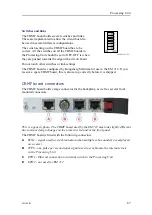
RIO-P board - dip switch setting
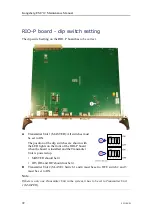
The dip switch setting on the RIO–P board has to be correct.
A
Transmitter Unit 1 (MASTER): All switches must
be set to ON.
The position of the dip switches are shown with
the LED lights on the front of the RIO-P board
when the board is installed and the Transmitter
Unit is powered up.
• MASTER should be lit.
• ID5, ID6 and ID7 should not be lit.
B
Transmitter Unit 2 (SLAVE): Switch 1 and 4 must be set to OFF, switch 2 and 3
must be set to ON.
Note
If there is only one Transmitter Unit in the system, it has to be set to Transmitter Unit
1 (MASTER).
Kongsberg EM 712 Maintenance Manual
Summary of Contents for EM 712
Page 8: ...8 451106 B Kongsberg EM 712 ...
Page 102: ...102 451106 B 216148 Transducer TX1 dimensions Kongsberg EM 712 Maintenance Manual ...
Page 103: ...451106 B 103 Drawing file ...
Page 104: ...104 451106 B 221048 Transducer TX2 dimensions Kongsberg EM 712 Maintenance Manual ...
Page 105: ...451106 B 105 Drawing file ...
Page 106: ...106 451106 B 219621 Transducer RX1 dimensions Kongsberg EM 712 Maintenance Manual ...
Page 107: ...451106 B 107 Drawing file ...
Page 108: ...108 451106 B 216146 Transducer RX2 dimensions Kongsberg EM 712 Maintenance Manual ...
Page 109: ...451106 B 109 Drawing file ...
Page 110: ...110 451106 B 223137 Transducer mounting frame 0 5 Kongsberg EM 712 Maintenance Manual ...
Page 111: ...451106 B 111 Drawing file ...
Page 112: ...112 451106 B 223139 Transducer mounting frame 1 Kongsberg EM 712 Maintenance Manual ...
Page 113: ...451106 B 113 Drawing file ...
Page 114: ...114 451106 B 223273 Transducer mounting frame 2 Kongsberg EM 712 Maintenance Manual ...
Page 115: ...451106 B 115 Drawing file ...
Page 116: ...116 451106 B 317812 Casing w mounting frame 0 5 Kongsberg EM 712 Maintenance Manual ...
Page 117: ...451106 B 117 320320 Casing w mounting frame 1 Drawing file ...
Page 118: ...118 451106 B 375817 Combined casing w mounting frame 1 Kongsberg EM 712 Maintenance Manual ...
Page 119: ...451106 B 119 331369 Casing w mounting frame 2 Drawing file ...
Page 120: ...120 451106 B 396402 EM 712 Transmitter Unit dimensions Kongsberg EM 712 Maintenance Manual ...
Page 121: ...451106 B 121 212984 EM 712 Transmitter Unit mounting bracket Drawing file ...
Page 122: ...122 451106 B 396428 EM 712 Receiver Unit dimensions Kongsberg EM 712 Maintenance Manual ...
Page 123: ...451106 B 123 385422 Processing Unit dimensions Drawing file ...
Page 124: ...124 451106 B 378828 Hydrographic Work Station dimensions Kongsberg EM 712 Maintenance Manual ...
Page 125: ...451106 B 125 Drawing file ...
Page 126: ...126 451106 B 371591 Rack installation kit dimenisons Kongsberg EM 712 Maintenance Manual ...
Page 127: ...451106 B 127 370275 Remote Control Unit K REM dimensions Drawing file ...
Page 128: ...128 451106 B Kongsberg EM 712 Maintenance Manual ...
Page 129: ...451106 B 129 373962 Remote Control Unit K REM wiring diagram Drawing file ...
Page 130: ...130 451106 B 409067 Fibre cable kit Kongsberg EM 712 Maintenance Manual ...
Page 144: ...144 451106 B Height 408 mm Weight 10 kg Approximately Kongsberg EM 712 Maintenance Manual ...
Page 219: ...451106 B 219 7 Observe the handling rules for transducers Equipment handling ...
Page 231: ......
Page 232: ... 2019 Kongsberg Maritime ...


