PRECAUTIONS FOR HANDLING ELECTRICAL EQUIPMENT
To maintain the performance of the machine over a long period, and to prevent failures or troubles before they
occur, correct "operation", "maintenance and inspection" "troubleshooting", and "repairs" must be performed.
This section deals particularly with correct repair procedures for mechatronics components and is aimed at im-
proving the quality of repairs. For this purpose, it describes the working procedures in "Handling of electrical
equipment".
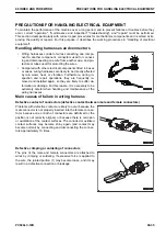
Handling wiring harnesses and connectors
• Wiring harnesses consist of wires connecting one compo-
nent to another component, connectors used for connect-
ing and disconnecting one wire from another wire, and pro-
tectors or tubes used for protecting the wires.
• Compared with other electrical components fitted in boxes
or cases, wiring harnesses are likely to be directly affected
by rain water, heat, or vibration. Furthermore, during in-
spection and repair operations, they are frequently re-
moved and installed again, so they are likely to suffer de-
formation or damage. For this reason, it is necessary to be
extremely careful when handling and maintenance of the
wiring harnesses.
Main causes of failure in wiring harness
Defective contact of connectors (defective contact between male and female connectors)
Problems with defective contact are likely to occur because the
male connector is not properly inserted into the female connec-
tor,or because one or both of connectors are deformed or the
position is not correctly aligned, or because there is corrosion
or oxidization of the contact surfaces. The corroded or oxidized
contact surfaces may become shiny again (and contact may
become normal) by connecting and disconnecting the connec-
tors approximately 10 times.
Defective crimping or soldering of connectors
The pins of the male and female connectors are attached to
wires by crimping or soldering. If excessive force is applied to
the wire, the jointed portion (1) may become loose, and it may
result in a defective connection or breakage.
00 INDEX AND FOREWORD
PRECAUTIONS FOR HANDLING ELECTRICAL EQUIPMENT
PC500LC-10R
00-35
Summary of Contents for PC500LC-10R
Page 1: ...HYDRAULIC EXCAVATOR SEN06722 00 PC500LC 10R SERIAL NUMBERS 100001 and up...
Page 2: ......
Page 3: ...00 INDEX AND FOREWORD PC500LC 10R 00 1...
Page 76: ......
Page 77: ...01 SPECIFICATIONS PC500LC 10R 01 1...
Page 94: ......
Page 95: ...10 STRUCTURE AND FUNCTION PC500LC 10R 10 1...
Page 177: ...When balanced 10 STRUCTURE AND FUNCTION CLSS PC500LC 10R 10 83...
Page 178: ...When lever is returned to fine control state CLSS 10 STRUCTURE AND FUNCTION 10 84 PC500LC 10R...
Page 179: ...When lever is pulled at a stroke 10 STRUCTURE AND FUNCTION CLSS PC500LC 10R 10 85...
Page 180: ...When lever is in stroke end CLSS 10 STRUCTURE AND FUNCTION 10 86 PC500LC 10R...
Page 377: ...20 STANDARD VALUE TABLE PC500LC 10R 20 1...
Page 407: ...30 TESTING AND ADJUSTING PC500LC 10R 30 1...
Page 583: ...30 TESTING AND ADJUSTING METHOD FOR STARTING UP KOMTRAX TERMINAL PC500LC 10R 30 177...
Page 604: ......
Page 605: ...60 MAINTENANCE STANDARD PC500LC 10R 60 1...
Page 636: ...MAINTENANCE STANDARD OF MAIN PUMP 60 MAINTENANCE STANDARD 60 32 PC500LC 10R...
Page 638: ...MAINTENANCE STANDARD OF SWING MOTOR 60 MAINTENANCE STANDARD 60 34 PC500LC 10R...
Page 641: ...60 MAINTENANCE STANDARD MAINTENANCE STANDARD OF TRAVEL MOTOR PC500LC 10R 60 37...
Page 644: ...MAINTENANCE STANDARD OF CONTROL VALVE 60 MAINTENANCE STANDARD 60 40 PC500LC 10R...
Page 646: ...MAINTENANCE STANDARD OF CONTROL VALVE 60 MAINTENANCE STANDARD 60 42 PC500LC 10R...
Page 648: ...MAINTENANCE STANDARD OF CONTROL VALVE 60 MAINTENANCE STANDARD 60 44 PC500LC 10R...
Page 650: ...MAINTENANCE STANDARD OF CONTROL VALVE 60 MAINTENANCE STANDARD 60 46 PC500LC 10R...
Page 652: ...MAINTENANCE STANDARD OF CONTROL VALVE 60 MAINTENANCE STANDARD 60 48 PC500LC 10R...
Page 658: ...MAINTENANCE STANDARD OF TRAVEL PPC VALVE 60 MAINTENANCE STANDARD 60 54 PC500LC 10R...
Page 668: ...MAINTENANCE STANDARD OF WORK EQUIPMENT LINKAGE 60 MAINTENANCE STANDARD 60 64 PC500LC 10R...
Page 679: ...90 CIRCUIT DIAGRAMS PC500LC 10R 90 1...
Page 692: ......
Page 694: ......
Page 696: ......
Page 698: ......
Page 700: ......
Page 704: ...Symbol Content Buzzer Antenna SYMBOLS USED IN ELECTRICAL CIRCUIT DIAGRAM 90 26 PC500LC 10R...
Page 706: ......
Page 708: ......
Page 710: ......
Page 712: ......
Page 714: ......
Page 716: ......
Page 718: ......
Page 720: ......
Page 722: ......
Page 724: ......
Page 726: ......
Page 728: ......
Page 730: ......
Page 732: ......
Page 734: ......
Page 736: ......
Page 738: ......
Page 740: ......
Page 742: ......
Page 744: ......
Page 746: ......
Page 748: ......
Page 757: ......

