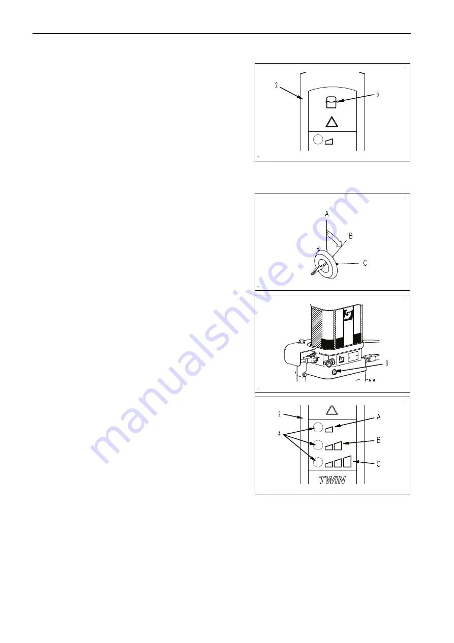
REMARK
Do not fill the reservoir before you have a low level indica-
tion (5) on the in-cab display.
SYSTEM TEST
In order to check the system a single lubrication cycle can be performed as follows:
1.
Move the starter switch to the ON position (B).
2.
Depress the test button (9) on the pump for three to five
seconds.
The system will run a run a single test. During this test the
green LED (4) of the selected interval on the in-cab display
(2) will flash (2 sec. on/ 2 sec. off).
In order to provide additional grease to all grease points (i.e. after cleaning the machine) or to vent the system a
continuous lubrication cycle run can be performed.
1.
Move the starter switch to the ON position (B).
2.
Depress the test button (9) on the pump for more than six seconds. The system will perform a continuous
lubrication test. During this run the green LED (4) of the selected interval on the in-cab display (2) will flash
(02 sec. on/ 0.2 sec. off).
3.
The continuous test cycle ends after the starter switch is moved to the OFF position (A).
A test cycle can only be started when the system is not in the pump phase of a current greasing cycle. If the
system is busy with a pump cycle, it will not react to the test push button.
KS000880
KS000884
KS000885
KS000878
AUTOMATIC GREASE SYSTEM
ATTACHMENTS AND OPTIONS
6-12
Summary of Contents for PC360LC-11
Page 2: ......
Page 22: ......
Page 76: ......
Page 344: ......
Page 425: ...SPECIFICATIONS 5 1 ...
Page 429: ...PC360NLC 11 SPECIFICATIONS SPECIFICATIONS 5 5 ...
Page 430: ......
Page 450: ...PC360LC 11 2 Piece Boom PC360NLC 11 2 Piece Boom 2 PIECE BOOM ATTACHMENTS AND OPTIONS 6 20 ...
Page 457: ...ATTACHMENTS AND OPTIONS 17M LONG REACH BOOM AND ARM 6 27 ...
Page 465: ...ATTACHMENTS AND OPTIONS SUPER LONG FRONT BOOM AND ARM 6 35 ...
Page 499: ...REPLACEMENT PARTS 7 1 ...
Page 515: ......


