background image

Foreword and general information

Handling of electric equipment

HB205-1, HB215LC-1

2 5


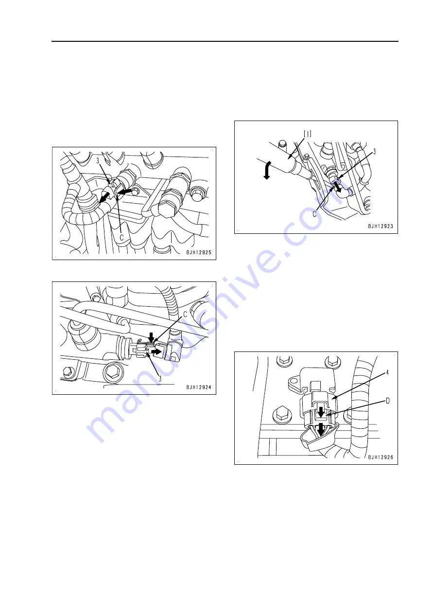
3) Push lock type (1)

q

95/107/114 series
Example) Fuel pressure sensor in
common rail 

(BOSCH-03)

Disconnection

While pressing lock (C), pull out connector
(3) in the direction of the arrow.

q

 114 series

q

107 series

a

If the lock is located on the underside, use
flat-head screwdriver [1] since you cannot
insert your fingers.
While pressing up lock (C) of the
connector with flat-head screwdriver [1],
pull out connector (3) in the direction of
the arrow.

Connection

Insert the connector straight until it "clicks".

4) Push lock type (2)

q

107/114 series
Example) Intake air pressure/tempera-
ture sensor in intake manifold

 (SUMI-

TOMO-04)

Disconnection

While pressing lock (D), pull out connector
(4) in the direction of the arrow.

Connection

Insert the connector straight until it "clicks".

00-25

Summary of Contents for HB205 -1

Page 1: ...HYDRAULIC EXCAVATOR SEN05393 06 HB205 1 HB215LC 1 SERIAL NUMBERS HB205 1001 HB215LC 1001 and up ...

Page 2: ...Find manuals at https best manuals com ...

Page 3: ...1 00 22 00 23 00 24 00 25 00 26 00 27 00 28 00 29 00 30 00 31 00 32 00 33 00 34 00 35 00 36 03 00 37 03 00 38 03 00 39 03 00 40 03 00 41 03 00 42 00 43 00 44 00 45 00 46 00 47 00 48 00 49 00 50 00 51 00 52 00 53 00 54 01 1 01 2 01 3 01 4 01 5 01 6 01 7 01 8 01 9 01 10 01 11 03 01 12 03 Mark Page Revision number 10 1 10 2 10 3 10 4 10 5 10 6 10 7 10 8 10 9 10 10 10 11 10 12 03 10 13 04 10 13 1 04 1...

Page 4: ...sion number 10 187 10 188 10 189 10 190 10 191 10 192 10 193 10 194 10 195 10 196 10 197 10 198 20 1 01 20 2 01 20 3 01 20 4 01 20 5 01 20 6 01 20 7 01 20 8 01 20 9 01 20 10 01 q 20 11 06 20 12 01 20 13 01 20 14 01 30 1 01 30 2 01 30 3 01 30 4 01 30 5 01 30 6 01 30 7 03 30 8 01 30 9 01 30 10 01 30 11 01 30 12 01 30 13 01 30 14 01 30 15 01 30 16 01 30 17 01 30 18 01 30 19 01 30 20 01 30 21 01 30 22...

Page 5: ... 29 01 40 30 01 40 31 01 40 32 01 40 33 01 40 34 01 40 35 01 40 36 01 Mark Page Revision number 40 37 01 40 38 01 40 39 01 40 40 01 40 41 01 40 42 01 40 43 01 40 44 03 40 45 03 40 46 03 40 47 03 40 48 03 40 49 03 40 50 03 40 51 03 40 52 01 40 53 01 40 54 01 40 55 01 40 56 01 40 57 01 40 58 01 40 59 01 40 60 01 40 61 01 40 62 01 40 63 01 40 64 01 40 65 01 40 66 01 40 67 01 40 68 01 40 69 01 40 70 0...

Page 6: ... 40 236 01 40 237 01 40 238 01 40 239 01 40 240 01 40 241 01 40 242 01 Mark Page Revision number 40 243 01 40 244 01 40 245 01 40 246 01 40 247 01 40 248 01 40 249 01 40 250 01 40 251 01 40 252 01 40 253 01 40 254 01 40 255 01 40 256 01 40 257 01 40 258 01 40 259 01 40 260 01 40 261 01 40 262 01 40 263 01 40 264 01 40 265 01 40 266 01 40 267 01 40 268 01 40 269 01 40 270 01 40 271 01 40 272 01 40 ...

Page 7: ...40 429 01 40 430 01 40 431 01 40 432 01 40 433 01 40 434 01 40 435 01 40 436 01 40 437 01 40 438 01 Mark Page Revision number 40 439 01 40 440 01 40 441 01 40 442 01 40 443 01 40 444 01 40 445 01 40 446 01 40 447 01 40 448 01 40 449 01 40 450 01 40 451 01 40 452 01 40 453 01 40 454 01 40 455 01 40 456 01 40 457 01 40 458 01 40 459 01 40 460 01 40 461 01 40 462 01 40 463 01 40 464 01 40 465 01 40 4...

Page 8: ...50 91 03 50 92 03 Mark Page Revision number 50 93 01 50 94 01 50 95 01 50 96 01 50 97 01 50 98 01 50 99 01 50 100 01 50 101 01 50 102 01 50 103 01 50 104 01 50 105 01 50 106 01 50 107 01 50 108 01 50 109 03 50 110 01 50 111 01 50 112 01 50 113 01 50 114 01 50 115 01 50 116 01 50 117 01 50 118 01 50 119 01 50 120 01 50 121 03 50 122 04 50 123 04 50 124 04 50 125 04 50 126 04 50 127 04 50 128 04 50 ...

Page 9: ...17 60 18 60 19 60 20 60 21 60 22 60 23 60 24 60 25 60 26 60 27 60 28 60 29 60 30 60 31 60 32 60 33 60 34 Mark Page Revision number 60 35 60 36 60 37 60 38 60 39 60 40 60 41 60 42 60 43 60 44 60 45 60 46 60 47 60 48 60 49 60 50 60 51 60 52 60 53 60 54 60 55 60 56 60 57 60 58 60 59 60 60 60 61 60 62 60 63 60 64 60 65 60 66 80 1 01 80 2 01 80 3 01 80 4 01 80 5 01 80 6 01 80 7 01 80 8 01 80 9 01 80 10...

Page 10: ...01 80 82 01 90 1 90 2 90 3 90 4 90 5 90 6 q 90 7 06 Q 90 7 2 06 90 9 90 10 90 11 90 12 90 13 90 15 90 17 90 19 90 21 90 23 1 01 2 03 3 03 4 03 5 03 6 03 7 03 q Colophon 06 Mark Page Revision number Mark Page Revision number Mark Page Revision number Mark Page Revision number 06 8 Find manuals at https best manuals com ...

Page 11: ...HB205 1 HB215LC 1 00 1 HB205 1 HB215LC 1 HYDRAULIC EXCAVATOR HB205 1 HB215LC 1 Machine model Serial number HB205 1 1001 and up HB215LC 1 1001 and up 00 Index and foreword 30 1 00 1 ...

Page 12: ...hybrid system 01 3 3 Specification dimension drawing 01 4 4 Working range diagram 01 5 5 Specifications 01 6 6 Weight table 01 9 9 Table of fuel coolant and lubricants 01 11 11 10 Structure and function Engine and cooling system 10 3 4 Engine related parts 10 3 4 Cooling system 10 4 5 Hybrid relation 10 6 7 Configuration and safety functions of hybrid system 10 6 7 Cooling system of hybrid compone...

Page 13: ... 19 Handling fuel system parts 30 20 20 Releasing remaining pressure from fuel system 30 20 20 Testing fuel system pressure 30 21 21 Cylinder cut out test mode operation 30 23 23 No injection cranking operation 30 23 23 Testing fuel delivery return rate and leakage 30 24 24 Bleeding air from fuel circuit 30 28 28 Testing fuel circuit for leakage 30 29 29 Handling of controller high voltage circuit...

Page 14: ...mbers 40 52 Information in troubleshooting table 40 55 Troubleshooting method for open circuit in wiring harness of pressure sensor system 40 57 Connector list and layout 40 59 Connection table for connector pin numbers 40 70 T branch box and T branch adapter table 40 106 Fuse location table 40 109 Troubleshooting by failure code 40 111 111 Failure code 989L00 Engine Controller Lock Caution 1 40 1...

Page 15: ...A452 Rail Press Sensor Low Error 40 178 Failure code CA488 Chg Air Temp High Torque Derate 40 180 Failure code CA553 Rail Press High Error 40 181 Failure code CA559 Supply Pump Press Low Error 1 40 182 Failure code CA689 Eng Ne Speed Sensor Error 40 184 Failure code CA731 Eng Bkup Speed Sens Phase Error 40 186 Failure code CA757 All Continuous Data Lost Error 40 187 Failure code CA778 Eng Bkup Spe...

Page 16: ...age drop 40 274 Failure code DW45KY swing holding brake Sol Val Pow Short Cir 40 276 Failure code DW4WKA Cancel Bucket Dump Open Circuit 40 278 Failure code DW4WKB Cancel Bucket Dump Short Circuit 40 280 Failure code DW91KA Travel Junction Sol Disc 40 282 Failure code DW91KB Travel Junction Sol S C 40 284 Failure code DWA2KA Attachment Sol Open Circuit 40 286 Failure code DWA2KB Attachment Sol Sho...

Page 17: ...Failure code GA19KT Int Abnorm Gen Mot Drv Sub CPU Con 40 383 Failure code GA19MA Gen Mot Drv Sub CPU Malfunction 40 383 Failure code GA19MC Gen Mot Drv Sub CPU Defect Operation 40 384 Failure code GA19NA Gen Mot Drv Sub CPU Start Disabled 40 384 Failure code GA1BMA Gen Mot Dr DC Vlt Sens Malfunction 40 385 Failure code GA1FKR Swing Mot Drv Communication Failure 40 385 Failure code GA1FMA Abnormal...

Page 18: ...n Open Short Cir 40 422 Failure code GA64MA Gen Mot Ph C Current Sen Malfunction 40 422 Failure code GA70KB HYB Swing Motor Short Circuit 40 423 Failure code GA70MD HYB Swing Motor Defective Stirr Motion 40 423 Failure code GA70NS HYB Swing Motor Overheat 40 424 Failure code GA71KZ HYB Swing Mot Temp Sens Opn Shrt Cir 40 426 Failure code GA72MA HYB Swing Motor Resolver Malfunction 40 428 Failure c...

Page 19: ...ion in troubleshooting table H mode 40 498 System diagram of hydraulic and mechanical system 40 496 H 1 Speed or power of all work equipment and travel is low 40 499 H 2 Engine speed lowers significantly or engine stalls 40 501 H 3 All work equipment and travel systems do not work 40 502 H 4 Unusual noise comes out from around hydraulic pump 40 502 H 5 Auto decelerator does not operate 40 503 H 6 ...

Page 20: ...tric swing motor temperature increases abnormally 40 550 Y 9 Motor generator temperature increases abnormally 40 552 Y 10 Inverter overheats 40 553 Y 11 Capacitor overheats 40 554 50 Disassembly and assembly General information on disassembly and assembly 50 4 How to read Disassembly and Assembly 50 4 Precautions related to hybrid machine 50 6 Coating materials list 50 7 Special tools list 50 10 S...

Page 21: ...emoval and installation of hydraulic tank assembly 50 183 Removal and installation of main pump assembly 50 188 Removal and installation of main pump input shaft oil seal 50 193 Removal and installation of control valve assembly 50 194 Disassembly and assembly of control valve 50 199 Disassembly and assembly of work equipment PPC valve assembly 50 203 Disassembly and assembly of travel PPC valve 5...

Page 22: ...troubleshooting 80 18 Circuit diagram and arrangement of connector pins 80 20 System diagram 80 22 Detail of air conditioner unit 80 24 Parts and connectors layout 80 26 Testing air leakage duct 80 30 Testing with self diagnosis function 80 31 Testing temperature control 80 34 Testing vent mode changeover 80 36 Testing FRESH RECIRC air changeover 80 39 Testing inner sensor 80 41 Testing evaporator...

Page 23: ...ng and connecting air conditioner piping 80 76 Handling of compressor oil 80 78 Desiccant replacement procedure 80 80 90 Diagrams and drawings Hydraulic circuit diagram 90 3 3 Symbols used in hydraulic circuit diagrams 90 3 3 Hydraulic circuit diagram 90 7 7 Electrical circuit diagram 90 9 7 Symbols used in electric circuit diagrams 90 9 7 Electrical circuit diagram 90 13 9 Index 1 03 00 3 10 ...

Page 24: ...h Law concerning electricity k 3 Never disassemble the hybrid devic es mentioned above The hybrid devic es and high voltage wiring orange color must be replaced by the unit k 4 When handling hybrid devices be sure to discharge the capacitor com pletely first For details see this man ual Handling of hybrid devices and high voltage wirings Discharge pro cedure for capacitor or Testing and adjusting ...

Page 25: ...ure to lock all the control levers and hang warning tag on them 3 When disassembling or assembling support the machine with blocks jacks or stands before starting the work 4 Remove all mud and oil from the steps or other places used to get on and off the machine Always use the handrails ladders or steps when getting on or off the machine Never jump on or off the machine If it is impossible to use ...

Page 26: ... is operated for a long time in a place which is not ventilated well you may suffer from gas poisoning Accordingly open the windows and doors to ventilate well 5 Precautions for slinging work and making signals 1 Only one appointed worker must make signals and co workers must communicate with each other frequently The appointed signaler must make specified signals clearly at a place where he is we...

Page 27: ...al of the crane carefully in advance and oper ate the crane safely 7 Precautions for using overhead traveling crane k A hoist crane or similar device must be used for lifting a heavy load 25 kg or more The weight of a part that is 25 kg or more is indicated with the symbol 4 in Disassembly and assembly 1 Before starting work inspect the wire ropes brake clutch controller rails over wind stop devic...

Page 28: ...4a to the atmosphere k If the refrigerant gas gets in your eyes or contacts your skin you may lose your sight or your skin may be frozen Whenever recovering or adding refrig erant gas you must put on safety glasses safety gloves and long sleeved clothes The refrigerant gas must be recovered and added by a qualified person 2 Connection 1 When installing the air conditioner circuit hoses and tubes t...

Page 29: ...nd out failed parts and how to repair them The troubleshooting is divided by failure modes The S mode of the troubleshooting related to the engine may be also explained in the Chassis volume and Engine volume In this case see the Chassis volume 50 Disassembly and assembly This section explains the special tools and procedures for removing installing disassembling and assem bling each component as ...

Page 30: ...anual the units are indicated with International System of units SI For reference conventionally used Gravitational System of units is indicated in parentheses Symbol Item Description k Safety Special safety precautions which are necessary when performing work are described a Caution Special technical precautions or other precautions for preserving standards which are necessary when performing wor...

Page 31: ...d by the tolerance q Indication of dimension of rotating shaft and hole and their related drawing 2 Standard clearance and standard value q The clearance made when new parts are as sembled is called the standard clearance which is indicated by the range from the min imum clearance to the maximum clearance q When some parts are repaired the clearance is generally adjusted to the standard clear ance...

Page 32: ...However since most of the allowable values are esti mated from various tests or experiences in most cases it must be judged after consider ing the operating condition and customer s requirement 5 Allowable clearance q Parts can be used until the clearance be tween them is increased to a certain limit The limit at which those parts cannot be used is called the allowable clearance q If the clearance...

Page 33: ...exchange Disassembly and maintenance of hydraulic components should be performed in a specially prepared dustproof workshop and the perfor mance should be checked with special test equipment 3 Sealing openings After any piping or equipment is removed the openings should be sealed with caps tapes or vinyl bags to prevent any dirt or dust from entering If the opening is left open or is blocked with ...

Page 34: ...udge in it will mix with the new oil and will shorten the life of the hydraulic oil 6 Flushing operations After disassembling and assembling the equip ment or changing the oil use flushing oil to remove the contaminants sludge and old oil from the hydraulic circuit Normally flushing is performed twice Primary flushing is performed by use of flushing oil and secondary flushing is performed by use o...

Page 35: ...ose joint 2 into mating adapter 3 Fig 1 a The adapter can be pushed in about 3 5 mm a Do not hold rubber cap portion 4 2 With hose joint 2 pushed into adapter 3 press rubber cap portion 4 against adapter 3 until it clicks Fig 2 3 Hold hose adapter 1 or hose 5 and pull it out Fig 3 a Since some hydraulic oil flows out pre pare an oil container 2 Connection 1 Hold hose adapter 1 or hose 5 and insert...

Page 36: ...ing 6 contacts contact surface a of the hexagonal portion at the male end Fig 6 2 While holding the condition of Step 1 turn lever 8 to the right clockwise Fig 7 3 While holding the condition of Steps 1 and 2 pull out whole body 7 to disconnect it Fig 8 2 Connection q Hold the tightening portion and push body 7 straight until sliding prevention ring 6 con tacts contact surface a of the hexagonal p...

Page 37: ...hexagonal portion at the male end Fig 10 2 While holding the condition of Step 1 push cover 10 straight until it contacts contact surface b of the hexagonal portion at the male end Fig 11 3 While holding the condition of Steps 1 and 2 pull out whole body 9 to disconnect it Fig 12 2 Connection q Hold the tightening portion and push body 9 straight until sliding prevention ring 8 con tacts contact s...

Page 38: ...kely to be affected by the direct effects of rain water heat or vibration Furthermore during inspection and repair operations they are frequently removed and installed again so they are likely to suffer deformation or damage For this reason it is necessary to be extremely careful when handling wiring harnesses 2 Main failures occurring in wiring harnesses 1 Defective contact of connectors defectiv...

Page 39: ...e time if water does enter it is difficult for it to be drained Therefore if water should get into the connector the pins will be short circuited by the water so if any water gets in immediately dry the connector or take other appropriate action before passing electricity through it 5 Oil or dirt stuck to connector If oil or grease are stuck to the connector and an oil film is formed on the mating...

Page 40: ...e connectors apart a Never pull with one hand 2 When removing from clips q Both of the connector and clip have stoppers which are engaged with each other when the connector is in stalled q When removing a connector from a clip pull the connector in a parallel di rection to the clip for removing stop pers a If the connector is pried up and down or to the left or right the housing may break 3 Action...

Page 41: ...l not to make them too hot as this will cause short circuits a If there is any damage or breakage replace the connector 2 Fix the connector securely Position the connectors correctly and then fit them securely For connectors with the lock stopper push in the connector until the stopper clicks into position 3 Correcting protrusion of the boot and misalignment of the wiring harness For connectors fi...

Page 42: ...ight of figure 1 Push in female connector 2 horizontally until the lock clicks Arrow 1 2 Since locks a and b may not be set completely push in female connector 2 while moving it up and down until the locks are set normally Arrow 1 2 3 a Right of figure Lock a is pulled down not set completely and lock b is set completely 1 Male connector 2 Female connector a b Locks q Disconnection q Connection Ex...

Page 43: ...ere is the risk that oil in the air may cause defective con tact remove oil and water in the air before starting air blow 2 Dry the inside of the connector with a dryer If water gets inside the connector use a dryer to dry the connector a Hot air from the dryer can be used but regulate the time that the hot air is used in order not to make the connec tor or related parts too hot as this will cause...

Page 44: ...bient pressure sensor PAMB 125 170 12V140 series Disconnection 1 Slide lock L1 to the right 2 While pressing lock L2 pull out connector 1 toward you a Even if lock L2 is pressed connector 1 cannot be pulled out toward you if part A does not float In this case float part A with a small screwdriver while pressing lock L2 and then pull out connector 1 toward you Connection Insert the connector straig...

Page 45: ...he underside use flat head screwdriver 1 since you cannot insert your fingers While pressing up lock C of the connector with flat head screwdriver 1 pull out connector 3 in the direction of the arrow Connection Insert the connector straight until it clicks 4 Push lock type 2 q 107 114 series Example Intake air pressure tempera ture sensor in intake manifold SUMI TOMO 04 Disconnection While pressin...

Page 46: ...f fuel supply pump G SUMITOMO 3 a Pull the connector straight up Connection Insert the connector straight until it clicks 6 Turn housing type Round green connector q 140 series Example Intake air pressure sensor in intake manifold CANNON 04 PIM etc Disconnection 1 Turn housing H1 in the direction of the arrow a When connector is unlocked housing H1 becomes heavy to turn 2 Pull out housing H1 in th...

Page 47: ...welding on the machine body disconnect all of the wiring harness connectors connected to the controller Fit an arc welding ground to the place close to the welding point 6 Points to remember when troubleshooting electric circuits 1 Be sure to turn the power OFF before discon necting or connecting connectors 2 Before performing troubleshooting check all the related connectors for loose connection a...

Page 48: ... nominal No Size Nominal No is shown in Table 2 Indicates type of wire by symbol Type symbol and material of wire are shown in Table 1 Since the use of AV AVS AVSS and CAVS wires depend on size nominal No their symbols are not indicated on the diagram Table 1 Type Symbol Material Using tempera ture range C Example of use Low voltage wire for automobile AV Conductor Annealed copper for electric app...

Page 49: ...ft polyvinyl chloride Heat resistant low voltage wire for automobile PEXBS Conductor Annealed copper wire for electric appliances 50 to 120 For signal wiring in high tempera ture place nominal size 0 5 3 cores Insulator Thin low capacitance crosslinked polyethylene Shield Sn plated annealed braided copper wire Sheath Heat resistant crosslinked polyethylene Braided shield wire for automobile CAVSBS...

Page 50: ...6 AEX Standard 2 0 2 2 2 7 3 0 3 1 3 8 4 6 AVSS Standard 2 7 2 7 Nominal No 8 15 20 30 40 50 60 85 100 Conduc tor Number of strands Diame ter of strand 50 0 45 84 0 45 41 0 80 70 0 80 85 0 80 108 0 80 127 0 80 169 0 80 217 0 80 Sectional area mm2 7 95 13 36 20 61 35 19 42 73 54 29 63 84 84 96 109 1 d approx 3 7 4 8 6 0 8 0 8 6 9 8 10 4 12 0 13 6 Cover D AVS Standard AV Standard 5 5 7 0 8 2 10 8 11...

Page 51: ...This as a preview PDF file from best manuals com Download full PDF manual at best manuals com ...

Reviews: