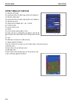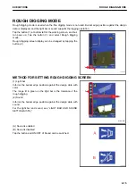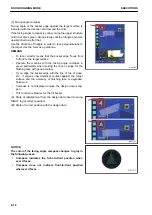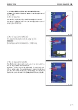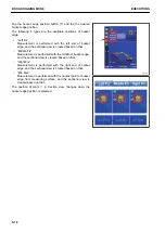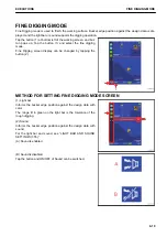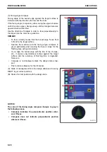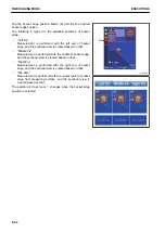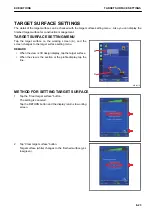
OFFSET MENU OF SURFACE
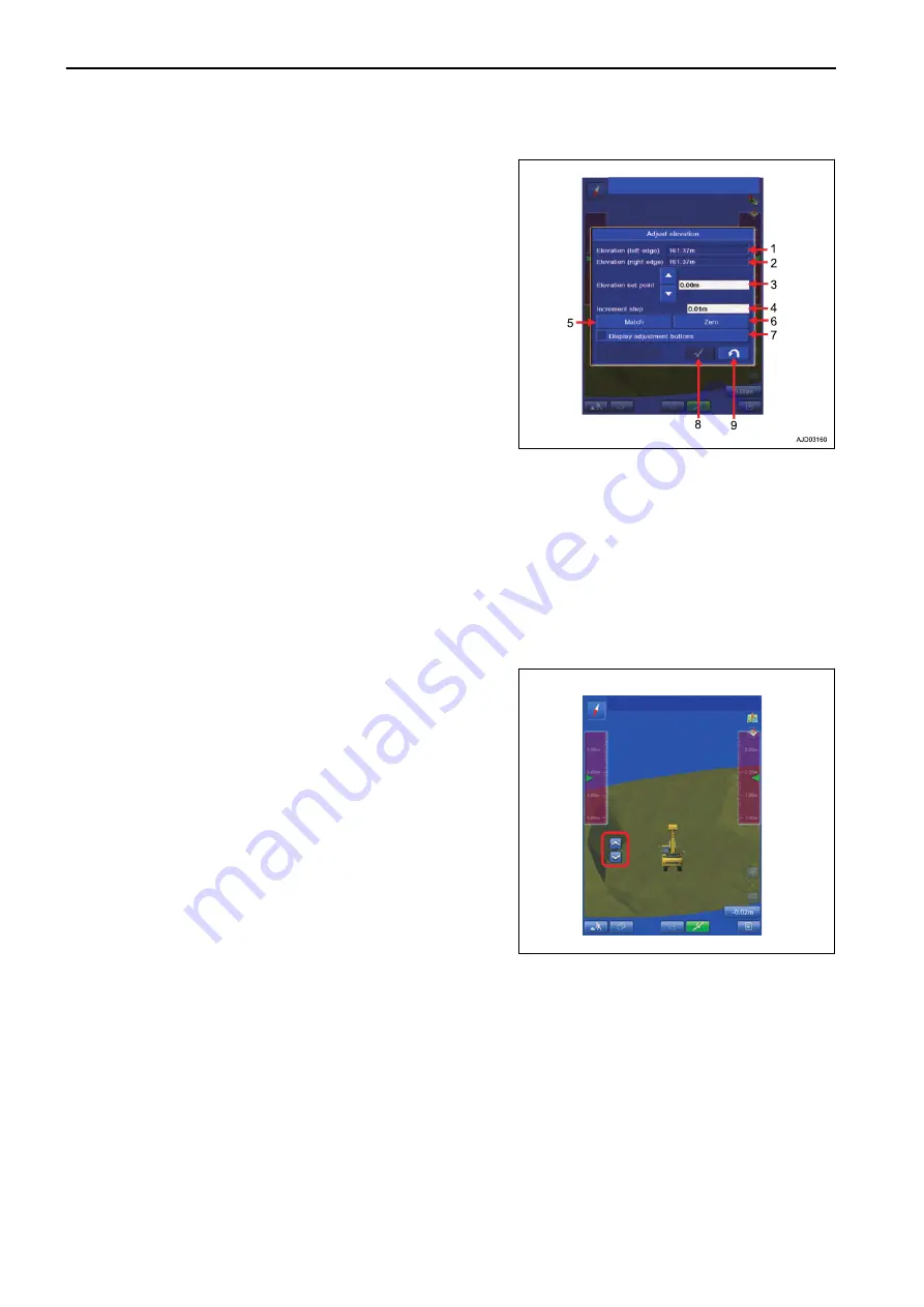
(1) “Elevation (left edge)”
The height (elevation) of bucket edge at left end is displayed.
(2) “Elevation (right edge)”
The height (elevation) of bucket edge at right end is displayed.
(3) “Elevation set point”
The offset value is adjusted with
△
and
▽
buttons.
(4) “Increment step”
The range of offset is set.
(5) “Match”
The current bucket edge height is set to 0.
The offset amount is automatically calculated so that the dis-
tance between the bucket edge and the design data becomes
0.
(6) “Zero”
The offset amount returns to 0 (default value).
(7) “Display adjustment buttons”
Put a tick in check box, and you can set the offset value on the working screen.
(8) ENTER button
Tap this button and new setting is saved.
(9) RETURN button
Tap this button and the display returns to the previous screen.
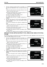
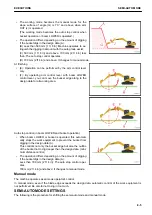
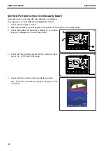
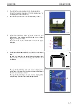
In case of “Display adjustment buttons”
TRAVEL MODE
EXECUTIONS
8-12
Summary of Contents for A31001
Page 12: ...LOCATION OF SAFETY LABELS Options are shown with marks in the figure SAFETY LABELS SAFETY 2 4...
Page 106: ......
Page 107: ...SPECIFICATIONS 5 1...
Page 110: ......
Page 116: ......
Page 117: ...SETTING 7 1...
Page 311: ...EXECUTIONS 8 1...
Page 376: ...PC360LCi 11 PC390LCi 11 HYDRAULIC EXCAVATOR Form No CEAM032703...


