background image

CEN00002-05

00 Index and foreword

26

Manual DC link capacitor discharge procedure

Follow any and all local and site specific procedures
and requirements for working on off-highway mining
equipment.

Verify that:

  • The engine is off and the parking brake is on.

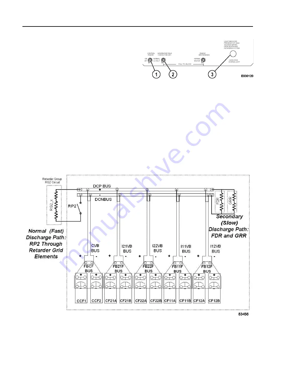
  • The generator field is cut out via GF cutout switch

(2, Figure 00-4) in the low voltage area of the
control cabinet.

1. Apply control power for a minimum of 30 sec-

onds. Then, turn off control power using control
power switch (1) on the switch panel.

With control power on, an RP contactor closes
and discharges the DC link through the
retarding grids in less than 10 seconds.

In most control cabinets, RP2 is the normal discharge
path. In groups containing an RP3 contactor, RP2
and RP3 are alternated as the normal discharge
path. Refer to Figure 00-5.

FIGURE 00-4. INFORMATION DISPLAY PANEL

1. Control Power Switch
2. GF Cutout Switch

3. Capacitor Charge 

Light

FIGURE 00-5.  DISCHARGE PATHS

Summary of Contents for 960E-1 -

Page 1: ...CEBM023802 Shop Manual DUMP TRUCK SERIAL NUMBERS A30025 A30026 ...

Page 2: ...Find manuals at https best manuals com ...

Page 3: ...EN00011 02 DUMP TRUCK 1SHOP MANUAL 960E Machine model Serial number 960E 1 A30025 A30026 00 Index and foreword Index Composition of shop manual 2 Table of contents 4 Find manuals at https best manuals com ...

Page 4: ...e Form Number Shop Manual contents binder binder label and tabs CEBM023802 00 Index and foreword Index CEN00011 02 Foreword safety and general information CEN00002 04 Operating instructions CEN00003 02 01 Specification Specification and technical data CEN01001 04 10 Structure function and maintenance standard Steering circuit CEN10001 04 Hoist circuit CEN10002 01 Brake circuits CEN10003 02 Suspens...

Page 5: ...0007 02 Troubleshooting by failure code Part 6 CEN40016 00 Cab air conditioning CEN40008 01 Reserve engine oil system CEN40010 00 50 Disassembly and assembly General information CEN50001 05 Wheels spindle and rear axle CEN50002 04 Brake system CEN50003 05 Steering system CEN50004 05 Suspensions CEN50005 06 Hoist circuit CEN50006 04 Operator cab CEN50007 03 Body and structures CEN50008 03 Cab air c...

Page 6: ...andling electrical equipment and hydraulic components 30 How to read electric wire code 38 Standard torque tables 41 Conversion tables 46 Operating instructions CEN00003 02 Preparing for operation 3 Engine start up 7 After engine start up 8 Emergency steering system 8 Precautions during truck operation 9 Operating on a haul road 10 Starting on a grade with a loaded truck 11 Sudden loss of engine p...

Page 7: ... warning circuit operation 7 Brake assembly wear data 9 Suspensions CEN10004 01 General information 3 Front suspension wear data 3 Rear suspension wear data 4 Electrical system 24V CEN10028 01 Battery supply system 3 Engine starting system 4 Auxiliary control cabinet components 5 Relay boards 7 Body up switch 11 Hoist limit switch 12 Interface module IM CEN10006 01 General information 3 Sensors 3 ...

Page 8: ... checkout data sheet 16 Hydraulic system flushing procedure 17 Brake system CEN30003 02 General information on system checkout 3 Brake circuit checkout procedure 3 Brake system checkout data sheet 13 Brake piston leakage test 17 Brake seal pressure test 17 Wet disc brake bleeding procedure 18 Parking brake bleeding procedure 18 Brake disc wear inspection 19 Brake valve bench test and adjustment 21...

Page 9: ... 6 Fault Code A005 Left rear suspension pressure sensor signal high 7 Fault Code A006 Left rear suspension pressure sensor signal low 8 Fault Code A007 Right rear suspension pressure sensor signal high 9 Fault Code A008 Right rear suspension pressure sensor signal low 10 Fault Code A009 Incline sensor signal high 11 Fault Code A010 Incline sensor signal low 12 Fault Code A011 Payload meter speed s...

Page 10: ...ing a false low fuel level 14 Fault Code A166 Left rear hydraulic oil temperature sensor is low 16 Fault Code A167 Right rear hydraulic oil temperature sensor is low 18 Fault Code A168 Left front hydraulic oil temperature sensor is low 20 Fault Code A169 Right front hydraulic oil temperature sensor is low 22 Fault Code A170 Left rear hydraulic oil temperature sensor is high 24 Fault Code A171 Righ...

Page 11: ...isplay panel is defective 40 Fault Code A249 Red warning lamp within the dash display driven by IM is shorted 41 Fault Code A250 Battery voltage is low with the truck parked 42 Fault Code A251 Sonalert used with the dash display driven by IM is open or shorted to ground44 Fault Code A252 Start enable output circuit is either open or shorted to ground 46 Fault Code A253 Steering bleed circuit is no...

Page 12: ... sensing is producing low readings 18 Fault Code A313 DCDC converter 12 volt circuit sensing is producing high readings 19 Fault Code A315 DCDC converter 12 volt circuit is low 20 Fault Code A316 Starter engagement has been attempted with engine running 22 Fault Code A317 Operation of brake auto apply valve without a detected response 24 Fault Code A318 Unexpected power loss to interface module 26...

Page 13: ...EN50001 05 Special tools 3 Wheels spindles and rear axles CEN50002 04 General information for tires and rims 3 Removal and installation of front wheel 4 Removal and installation of rear wheel 6 Removal and installation of tires 8 Removal and installation of front wheel hub and spindle 10 Disassembly and assembly of front wheel hub and spindle 17 Removal and installation of rear axle 22 Removal and...

Page 14: ...ld 11 Removal and installation of rear suspension 14 Disassembly and assembly of rear suspension 17 Hoist circuit CEN50006 04 Removal and installation of hoist pump 3 Disassembly and assembly of hoist pump 5 Removal and installation of hoist valve 13 Disassembly and assembly of hoist valve 14 Overcenter valve manifold service 21 Removal and installation of hoist pilot valve 22 Disassembly and asse...

Page 15: ...cal circuit diagram index symbols XS5701 Electrical circuit diagram circuit locator sheet XS5702 Electrical circuit diagram circuit locator sheet XS5703 Electrical circuit diagram battery box XS5704 Electrical circuit diagram 24V power distribution circuit protection XS5705 Electrical circuit diagram 24V power distribution circuit protection XS5706 Electrical circuit diagram engine control wiring ...

Page 16: ...ram diagnostic ports GE XS5726 Electrical circuit diagram diagnostic ports VHMS GE XS5727 Electrical circuit diagram modular mining interface XS5728 Electrical circuit diagram interface module inputs outputs XS5729 Electrical circuit diagram interface module inputs outputs XS5730 Electrical circuit diagram interface module inputs outputs XS5731 Electrical circuit diagram interface module inputs ou...

Page 17: ...00 Index and foreword CEN00011 02 15 NOTES ...

Page 18: ...16 CEN00011 02 00 Index and foreword 960E Dump truck Form No CEN00011 02 2011 KOMATSU All Rights Reserved Printed in USA 11 11 ...

Page 19: ...utions before operating the truck 10 Precautions while operating the truck 12 Working near batteries 15 Precautions before performing service 17 Precautions while performing service 19 Tires 21 Precautions for performing repairs 22 Precautions for welding on the truck 23 Capacitor discharge system 24 Handling electrical equipment and hydraulic components 32 How to read electric wire code 40 Standa...

Page 20: ...ause cancer birth defects or other reproductive harm CALIFORNIA Proposition 65 Warning Battery posts terminals and related accessories contain lead and lead compounds chemicals known to the State of California to cause cancer and birth defects or other reproductive harm Wash hands after handling Unsafe use of this machine may cause serious injury or death Operators and maintenance person nel must ...

Page 21: ...accord ingly use of such parts may compromise the safe operation of Komatsu products and place the operator and others in danger should the part fail Komatsu is also aware of repair companies that will rework or modify an OEM part for reuse in critical systems Komatsu does not generally authorize such repairs or modifications for the same reasons as noted above Use of non OEM parts places full res...

Page 22: ... to specific torque values standard torque values should be used Standard torque values are shown in torque charts later in this section Specific torques when provided in the text are in bold face type such as 135 N m 100 ft lb All torque specifications have 10 tolerance unless otherwise specified A product identification plate is located on the frame in front of the right side front wheel It desi...

Page 23: ... and to judge parts in troubleshooting 30 Testing and adjusting This section explains measuring instruments and measuring methods for testing and adjusting and method of adjusting each part The standard values and judgement criteria for testing and adjusting are explained in Testing and adjusting 40 Troubleshooting This section explains how to find out failed parts and how to repair them The troub...

Page 24: ...R identifies a specific potential hazard WHICH WILL RESULT IN EITHER INJURY OR DEATH if proper precautions are not taken WARNING identifies a specific potential hazard WHICH MAY RESULT IN EITHER INJURY OR DEATH if proper precautions are not taken CAUTION is used for general reminders of proper safety practices OR to direct the reader s attention to avoid unsafe or improper practices which may resu...

Page 25: ...s and seat belts Use these safety features properly Never remove any safety features Always keep them in good operating condition Improper use of safety features could result in serious bodily injury or death Check the seat belt fabric buckle and hardware for damage or wear Replace any worn or damaged parts immediately The seat belts must be replaced 5 years after seat belt manufacture or after ev...

Page 26: ... is moving When climbing on or off a truck face the truck and use the hand hold and steps Never hold any control levers when getting on or off a truck Always maintain three point contact with the hand holds and steps to ensure that you support yourself When bringing tools into the operator s compartment always pass them by hand or pull them up by rope If there is any oil grease or mud on the hand ...

Page 27: ...nd arm or any other part of your body between movable parts such as the dump body chassis or cylinders If the work equipment is operated clearances will change and may lead to serious bodily injury or death Unauthorized modification Any modification made to this vehicle without authorization from Komatsu America Corp can possibly create hazards Before making any modification consult the authorized...

Page 28: ...job site regulations In addition know the proper use and care of all the safety equipment on the truck Only qualified operators or technicians should attempt to operate or maintain a Komatsu machine Safe practices start before the operator gets to the equipment Safety at the worksite When walking to and from a truck maintain a safe distance from all machines even when the operator is visible Befor...

Page 29: ...hts work lights and taillights are in proper working order Make sure that the truck is equipped with the proper work lamps that are needed for the operating conditions In operator cab before starting the engine Do not leave tools or spare parts lying around Do not allow trash to accumulate in the cab of the truck Keep all unauthorized reading material out of the truck cab Keep the cab floor contro...

Page 30: ...d do not stand in front of the rim and locking ring when inflating a tire mounted on the truck Observers should not be permitted in the area and should be kept away from the side of such tires The tire and rim assembly may explode if subjected to excessive heat Personnel should move to a remote or protected location if sensing excessively hot brakes smelling burning rubber or observing evidence of...

Page 31: ...ictly observed even with machines equipped with a back up horn or rear view mirror Traveling on slopes Traveling on slopes could result in the truck tipping over or slipping Do not change direction on slopes To ensure safety drive to level ground before turning Do not travel up and down on grass fallen leaves or wet steel plates These materials may make the truck slip on even the slightest slope A...

Page 32: ... result in serious injury or death Remember that ground surfaces in these areas may be weakened after heavy rain or blasting Freshly laid soil and the soil near ditches is loose It can collapse under the weight or vibration of the truck Avoid these areas whenever possible Parking the truck Choose a flat level surface to park the truck If the truck has to be parked on a slope put blocks behind all ...

Page 33: ...or vegetable oil Call a doctor or poison prevention center immediately Always wear safety glasses or goggles when working with batteries Batteries generate hydrogen gas Hydrogen gas is very explosive and can easily be ignited with a small spark or flame Before working with batteries stop the engine and turn the key switch to the OFF position Avoid short circuiting the battery terminals through acc...

Page 34: ...ery disconnect switches to the ON position and attempt starting For booster cable removal disconnect the ground or negative cable first then the 24VDC cable last If any tool touches between the positive terminal and the chassis it will cause sparks Always use caution when using tools near the battery Jump starting with receptacles Always wear safety glasses or goggles when starting the machine wit...

Page 35: ... in the operator s seat to stop the engine if necessary During these situations never move any controls that are not related to the task at hand When servicing the truck do not to touch any moving parts Never wear loose clothing or jewelry Put wheel blocks under the wheels to prevent truck movement When performing service with the dump body raised place the dump lever in the HOLD position and appl...

Page 36: ...re that a proper cable sling is used 1 To hold the dump body in the up position raise the body to its maximum height 2 Install two shackles 2 Figure 00 1 and body retention sling 3 between rear body ear 1 and the axle housing 3 Secure the shackle pins with cotter pins 4 Move the hoist lever to the FLOAT position to slowly lower the body until the calbe is supporting the full weight of the body The...

Page 37: ...ter into the retarding grids Excess water in the retarding grids can cause a ground fault which will prevent propulsion Attachments Place attachments that have been removed from the truck in a safe place and manner to prevent them from falling Working under the truck Always lower all movable work equipment to the ground or to their lowest position before performing service or repairs under the tru...

Page 38: ...ng high pressure hoses Do not bend high pressure hoses or hit them with hard objects Do not use any bent or cracked piping tubes or hoses They may burst during use Always repair any loose or broken hoses If fuel or oil leaks it may result in a fire Precautions when performing maintenance near high temperature or high pressure Immediately after stopping operation engine coolant and operating oils a...

Page 39: ... consult your authorized regional Komatsu distributor or the tire manufacturer Refer to the Society of Automotive Engineers SAE SAE J1337 Off Road Rim Maintenance Procedures and Service Precautions Section 4 2 for additional information on demounting the tires and rim assem blies Also refer to Section 4 4 of SAE J1337 for assembly and inflation recommendations The U S Department of Labor Mine Safe...

Page 40: ...shutdown procedure after AC drive system failure If the AC drive system is operating normally when the engine is shut down the system should be safe to service However in the event of a drive system failure performing the following procedure before any maintenance activities will ensure that no hazardous voltages are present in the AC drive system 1 Before shutting down the engine verify the statu...

Page 41: ...bly cause damage to components Drain clean and ventilate fuel tanks and hydraulic tanks before making any welding repairs on the tanks Before welding on the truck disconnect all electrical harnesses from the modules and controllers inside the auxiliary control cabinet behind the operator cab Do not weld on the rear of the control cabinet The metal panels on the back of the cabinet are part of capa...

Page 42: ...ssary to adhere to the fol lowing instructions before touching or servicing drive system components Only authorized service person nel are allowed to service the drive system Refer to the shop manual for rules when servicing the drive system Adhere to the proper procedures for disabling the drive system Necessary tools 2000 VDC meter Figure 00 2 Komatsu p n PC3186 Bierer RCDC 1000 or equivalent Pe...

Page 43: ...not illuminated before opening the doors to the high voltage area or the high voltage contactor area Use measurement and protective equipment rated for 2000 VDC minimum to verify that no voltage is present before touching any terminal Verify functionality of the measurement equipment using site approved procedures both before and after performing control group measurements Failure to observe these...

Page 44: ...binet 1 Apply control power for a minimum of 30 sec onds Then turn off control power using control power switch 1 on the switch panel With control power on an RP contactor closes and discharges the DC link through the retarding grids in less than 10 seconds In most control cabinets RP2 is the normal discharge path In groups containing an RP3 contactor RP2 and RP3 are alternated as the normal disch...

Page 45: ... engine and capacitor charge lights are off Use measurement and protective equipment rated for 2000 VDC minimum to verify that no voltage is present before touching any terminal Verify functionality of the measurement equip ment using site approved procedures both before and after performing control group mea surements Failure to observe these precautions may result in death or serious personal in...

Page 46: ...d that high voltage is present in the high voltage area 1 Open the high voltage area doors 2 With a suitable high voltage meter rated for at least 2000 VDC such as PC3186 or equivalent plus suitable protective equipment measure the voltage across each of the DC link capacitors Place one meter lead on the positive capacitor terminal and the other meter lead on the negative capacitor terminal and ob...

Page 47: ...s voltages are present in this equip ment Avoid touching any energized equipment when the door to the low voltage area is open Failure to do so may result in personal injury and equipment damage 3 Discharge the relevant capacitors Open the door s and place one grounding stick on one of the positive capacitor terminals and the other on the diagonally located negative terminal Refer to Figure 00 8 a...

Page 48: ...control group mea surements Failure to observe these precautions may result in death or serious personal injury 4 Measure voltage on all capacitors as described in Failure of the discharge system on page 28 Discharge any capacitors that show voltage 5 If all capacitors read discharged verify that the meter is functioning correctly using site approved procedures If so proceed to Short isolated capa...

Page 49: ...t using site approved procedures both before and after performing control group mea surements Failure to observe these precautions may result in death or serious personal injury Any capacitor that is isolated from the DC link and confirmed discharged must have its terminals electri cally shorted together to prevent static charge build up Use bare wire to jumper all four terminals on the capacitor ...

Page 50: ... are more likely to be affected by the direct effects of rain water heat or vibration Furthermore dur ing inspection and repair operations they are frequently removed and installed again so they are likely to suffer deformation or damage For this reason it is necessary to be extremely careful when handling wiring harnesses 2 Main failures occurring in wiring harness Defective contact of connectors...

Page 51: ...This as a preview PDF file from best manuals com Download full PDF manual at best manuals com ...

Reviews: