USING THE WORK EQUIPMENT
138
3.13.7 CHANGING THE BUCKET OR THE EQUIPMENT WITH OPTIONAL
RAPID COUPLING
WARNING
q
Stop the machine on a firm and level surface and lower the equipment to the ground.
q
Before getting off the machine, stop the engine, release the residual pressure by moving the equipment
control lever more than once in all directions and lock the controls (safety bars lifted in vertical posi-
tion).
q
Clean the upper and lower areas involved in the installation of the bucket or the equipment, removing
any trace of dirt or debris, before connecting or disconnecting them to/from the rapid coupling.
q
Before starting work, make sure that the rapid coupling pins are completely engaged, that they protrude
from the tabs (slots) provided on the bucket or on the equipment and that the coupling levers are lowe-
red in horizontal position.
q
After locking the equipment and before starting work, make sure that the locking pins are correctly en-
gaged and that the length of the protruding parts of the pins is in compliance with the prescribed safety
values (see "3.13.7.3 CHECKING THE POSITION OF THE LOCKING PINS").
q
Lubricate the levers as required and remove any dirt or debris. Lubricate the connection pins as requi-
red and keep the area around the pins free of dirt and debris. Always grease the pins with the bucket re-
sting on the ground. Grease according to the routine maintenance schedule or when changing the
bucket.
q
Avoid using your fingers to align the holes, since they may be cut in case of sudden or uncontrolled mo-
vements.
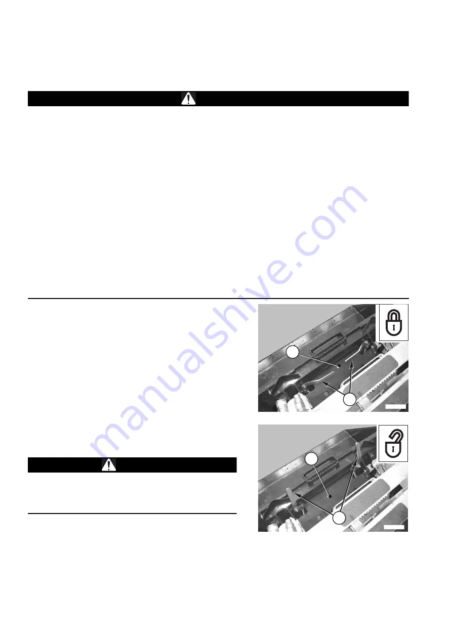
The loader has been designed in such a way as to allow va-
rious types of buckets or special equipment to be installed.
To facilitate the change procedure, the machine is equipped
with a special universal tool carrier, called "PAN-TACH", which
makes it possible to install and remove the bucket or the equi-
pment by means of spring-loaded levers and a pin latching sy-
stem that secures the machine coupling to the bucket or the
equipment.
LOCKING THE BUCKET OR THE EQUIPMENT
Rotate the levers (1) downwards in horizontal position.
RELEASING THE BUCKET OR THE EQUIPMENT
Rotate the levers (1) upwards in vertical position.
CAUTION
q
For the installation of equipment not described in this
manual, read and keep to the instructions given in the
user's manual supplied by the manufacturer of the equi-
pment in question.
2
RWAA9970
1
RWAA9960
2
1
Summary of Contents for 37BF50111
Page 2: ......
Page 17: ...SAFETY AND ACCIDENT PREVENTION 15...
Page 19: ...SAFETY NOISE AND VIBRATION PLATES 17 RWA00010 RWA37020...
Page 21: ...SAFETY NOISE AND VIBRATION PLATES 19 RWA37040 RWA00010 RWA00020...
Page 53: ...THE MACHINE AND ITS OPERATIONS 51...
Page 62: ...GENERAL VIEWS 60 10 Left console switches 11 Right console switches RWAA9720 11 RWAA11260 10...
Page 154: ...152 PAGE INTENTIONALLY LEFT BLANK...
Page 155: ...MAINTENANCE 153...
Page 205: ...TECHNICAL SPECIFICATIONS 203...
Page 213: ...TECHNICAL DATA 211 SOLID TYRES SIZE MAKE 10x16 5 AIR BOSS...
Page 214: ...212 PAGE INTENTIONALLY LEFT BLANK...
Page 215: ...AUTHORISED OPTIONAL EQUIPMENT 213...
Page 242: ...240 PAGE INTENTIONALLY LEFT BLANK...
Page 243: ......
Page 244: ...2004 KOMATSU UTILITY EUROPE S p A All Rights Reserved Printed in Europe...


