background image


Vers. 072821 


12 

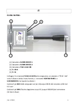
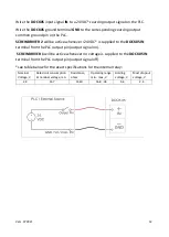
Wire the 

DOCK05

 input signal 

IN

 to a 24VDC* 

sourcing

 output signal on the PLC. 

Wire the 

DOCK05

 ground terminal 

GND

 to the corresponding 

sourcing

 output 

common ground pin on the PLC. 

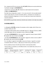
SCREWDRIVER 2

 will be active wh24VDC* is supplied to the 

DOCK05


IN


terminal from the PLC output pin (output signal on). 


SCREWDRIVER 1 

will be active whenever no voltage is supplied to the 

DOCK05


IN


terminal from the PLC output pin (output signal off). 

*see table below for the exact specifications for the internal relay: 

Nominal 
Voltage, V 

Rated coil consumption 
at nominal voltage, mA 

Resistance, 
ohms 

Operating range 
min - max, V 

Holding 
voltage, V 

Must dropout 
voltage, V 

24 

16.7 

1440 

16.8 - 36 

9.6 

2.4 


Summary of Contents for DOCK05

Page 1: ...standards and other normative documents 2006 42 CE LVD 2014 35 UE EMCD 2014 30 UE EN 62841 2 2 2014 EN 62841 1 2015 EN 60204 1 EN 61000 6 1 EN 61000 6 3 conforme alla direttiva RoHS III 2011 65 UE e s...

Page 2: ...Vers 072821 2 Manuale Istruzioni Operator s Manual DOCK05 KOLVER S r l VIA MARCO CORNER 19 21 36016 THIENE VI ITALIA TEL 39 0445 371068 www kolver it...

Page 3: ...mento 5 Selezione Avvitatore Tramite Programmi o Sequence K Ducer 6 Selezione Avvitatore Tramine Fonte Esterna PLC 7 Garanzia 8 English 9 13 Quick Start 9 Description 10 Screwdriver Selection Via K Du...

Page 4: ...OOL K DUCER dello sdoppiatore al connettore TOOL dell unit K Ducer tramite il cavo fornito e i connettori SCREWDRIVER 1 e SCREWDRIVER 2 ai rispettivi avvitatori Cablare il pin GND dello sdoppiatore al...

Page 5: ...selezione dell avvitatore viene controllata tramite un segnale di entrata a 24VDC sul pin IN rispetto alla corrispondente massa di riferimento GND L avvitatore SCREWDRIVER 1 attivo quando il segnale...

Page 6: ...er sezione Connessioni I O per progettare altri schemi di controllo DOCK05 Pin GND cablato a DOCK05 Pin IN DOCK05 cablato a SCREWDRIVER 1 attivo con SCREWDRIVER 2 attivo con KDU CN3 Pin 44 GND KDU CN3...

Page 7: ...e il segnale GND dello sdoppiatore alla massa del corrispettivo segnale di uscita sourcing del PLC o altra fonte esterna Mantenendo attivo il segnale di uscita sourcing a 24VDC verr selezionato l avvi...

Page 8: ...dei materiali 3 Questa garanzia non valida per quei prodotti che sono stati usati in modo non conforme o modificati o che non sono stati riparati da KOLVER o perch sono stati utilizzati ricambi non o...

Page 9: ...ER connector on DOCK05 to the TOOL connector on the K Ducer unit and SCREWDRIVER 1 and SCREWDRIVER 2 connectors on DOCK05 to the corresponding screwdrivers Wire the GND terminal on DOCK05 to pin 44 ou...

Page 10: ...whenever the IN signal is on 24VDC between IN and GND To power the input signal IN on DOCK05 one can utilize the K Ducer output signals on the CN3 connector of the K Ducer or an external source such...

Page 11: ...Pin 27 BIT3SQ K Ducer current sequence A B C H K Ducer current sequence D E F G KDU CN3 Pin 28 BIT1PR K Ducer current program even 2 4 6 62 64 K Ducer current program odd 1 3 5 61 63 BITxPR pins cann...

Page 12: ...plied to the DOCK05 IN terminal from the PLC output pin output signal on SCREWDRIVER 1 will be active whenever no voltage is supplied to the DOCK05 IN terminal from the PLC output pin output signal of...

Page 13: ...ree of charge such items 3 This guarantee does not cover repair or replacement required as a consequence of products which have been abused misused or modified or which have been repaired using not or...

Page 14: ...Vers 072821 14 Dimensioni Dimensions...

Reviews: