Kolver 190004 Operator'S Handbook Manual Download Page 10

Vers. 100919

EN

WARNING: To reduce  the risk of injury, before using or servicing the tool, read and understand
the  following  information  as  well  as  separately  provided  safety  instructions  (Item  number:
0MS000). The features and descriptions of our products are subject to change without prior notice.

1. Applications

KOLVER  electric  screwdrivers  are  used  to  tighten  to  the  required  torque  screws,  nuts,  studs  and
any  other  kind  of  threaded  connection  on  any  material.  Obviously,  it  is  possible  to  use  the
screwdrivers with screw having a larger diameter if the torque fall within the indicated range. All
models  are  reversible  and  can  consequently  be  used  to  unscrew.  Electric  screwdrivers  are  mainly
used in the electronic industry as well as for electric appliances, wiring, toys, lamps, glasses, in the
mechanical light industry etc.

2. Use

KOLVER screwdriving system is composed by a screwdriver, a cable with 2 x M12 female 5 pin
connectors and a power supply and control unit. To install it please follow the instructions.
a) Connect  the  connectors  of  the  cable  to  the  controller  and  to  the  screwdriver  and  tighten  the
relevant nuts.
b) Connect the controller plug to a main supply socket 90/230V- 50/60Hz.
c) Switch the controller on through the black button on the back panel.
d) Select  the  desired  setting  of  speed  (A)  through  the  relevant  knob.  Please  make  sure  that  such
setting is compatible with the torque setting. Since the speed reduction is obtained through a voltage
reduction  (=  power  reduction),  if  the torque  setting  is  too  high  for  a  low  speed  setting,  the  clutch
may not operate correctly and get stuck. In such a case, the driver will not run and when you press
the start lever the red light will signal. To reset the driver just turn the bit chuck until you hear the
clutch

“click” (usually 180°). Increase the speed setting before running the driver again.

e)

Do not slide the forward/reverse while the motor is running, it’s dangerous for the motor.

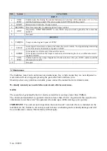
3. Adjusting the torque

The  torque  value  of  the  screwdriver  is  adjusted  by changing  the  tension  of  the  clutch  spring, i.e.
screwing or unscrewing the threaded nut. To increase the torque, turn the nut clockwise; to decrease
it, turn the nut anticlockwise.
To  change  the  spring  remove  the  nut,  replace  the  spring  and  then  adjust  the torque  value  as
mentioned above..

Summary of Contents for 190004

Page 1: ...s in conformity with the following standards and other normative documents 2006 42 CE LVD 2014 35 UE EMCD 2014 30 UE EN 62841 EN 60204 1 EN 61000 6 2 2005 AC 2005 and EN 61000 6 4 2007 A1 2011 conform...

Page 2: ...9 Manuale Istruzioni Operator s Handbook KBL Avvitatori Screwdrivers EDU1BL EDU1BL SG Unit di controllo Control units KOLVER S r l VIA MARCO CORNER 19 21 36016 THIENE VI ITALIA TEL 39 0445 371068 www...

Page 3: ...FR CA 190015 CA 0 4 1 5 650 1000 Hex EDU1BL SG KBL30FR CA 190030 CA 0 7 3 0 650 1000 KBL40FR CA 190040 CA 0 9 4 0 450 750 KBL04FR CA FN 190004 CA FN 0 04 0 4 650 1000 KBL15FR CA FN 190015 CA FN 0 4 1...

Page 4: ...nit Diritti Auto reverse Inline Auto reverse KBL04FR AR 190004 AR 0 04 0 4 650 1000 Hex EDU1BL KBL15FR AR 190015 AR 0 4 1 5 650 1000 KBL30FR AR 190030 AR 0 7 3 0 650 1000 KBL40FR AR 190040 AR 0 9 4 0...

Page 5: ...nello posteriore d Procedere all avvitatura assicurandosi che la velocit impostata garantisca sempre e comunque il corretto scatto della frizione Se non si verifica questo la frizione si pu bloccare L...

Page 6: ...ento dell avvitatore tramite un sofisticato regolatore switching da 120W Modelli KBL FR cavo 5 pin utilizzo con EDU 1BL L unit di controllo EDU1BL studiata per essere utilizzata con gli avvitatori del...

Page 7: ...con la punta di un cacciavite il cassettino portafusibile Unit di controllo Caratteristiche Dimensioni mm Peso kg EDU1BL 120W 1 connettore 5 pin velocit regolabile 130 x 118 x 67 0 6 EDU1FR 120W 1 con...

Page 8: ...tivato appare sul display la scritta STOP MOTOR ON il motore si fermer e non potr funzionare fino all apertura del contatto 5 NOT USED Utilizzato solo nelle versioni speciali OUTPUT 6 TORQUE Segnale d...

Page 9: ...o impiego sia stato limitato ad un unico turno per tutto quel periodo Se il ritmo d impiego supera il funzionamento di un unico turno la durata della garanzia sar ridotta in modo proporzionale 2 Se il...

Page 10: ...ble to the controller and to the screwdriver and tighten the relevant nuts b Connect the controller plug to a main supply socket 90 230V 50 60Hz c Switch the controller on through the black button on...

Page 11: ...cuts the power supply to the motor in response to the clutch action as soon as the pre set torque is reached On the front panel of the control unit you can find the A knob through which you can set t...

Page 12: ...slow start option ramp from 0 to 2 seconds i e the motor will reach the nominal speed gradually Dial 1 for no ramp and 10 for maximum ramp Knob A is used to adjust the motor speed for nominal speed i...

Page 13: ...4VDC 9 COM 0VDC Common pin for any output Signals must be taken between this pin 0VDC common and the other pins 6 7 and 8 10 Not used 5 Maintenance The brushless motor and control unit are maintenance...

Page 14: ...ee of charge such items 3 This guarantee does not cover repair or replacement required as a consequence of products which have been abused misused or modified or which have been repaired using not ori...

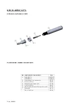
Page 15: ...Vers 100919 KBL04 15 30 40 FR ESPLOSO EXPLODED VIEW...

Page 16: ...netto Thrust bearing 251118 251118 251218 251418 19 Cuscinetto Bearing 251119 251119 251219 251419 20 Riduzioni Gears 251120 251120 251220 251420 21 Magnete Magnet 3 251021 251021 251021 251021 22 Sen...

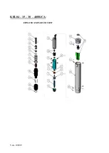
Page 17: ...Vers 100919 KBL04 15 30 40FR CA ESPLOSO EXPLODED VIEW...

Page 18: ...5 251015 16 Sfera Steel ball 2 251116 251116 251216 251416 17 Salterello Fixed clutch 251117 251117 251217 251417 18 Cuscinetto Thrust bearing 251118 251118 251218 251418 19 Cuscinetto Bearing 251119...

Page 19: ...DESCRIPTION COD 1 KBL04FR CA 190004 CA KBL15FR CA 190015 CA 2 Compensatore Axial compensator 800322 3 Vite Screw M3x5 T10 4 801003 4 Flangia supporto Support plate 251140 5 Vite Screw M3x5 200039 6 Bu...

Page 20: ...lla coppia Torque adjusting spring 251215 16 Sede frizione Clutch seat 251216 17 Camma Cam 251217 18 Sfera Steel ball 2 251218 19 Salterello Fixed clutch 251219 20 Corona riduzioni Gear assembly 25122...

Page 21: ...NE DESCRIPTION COD 1 KBL30FR CA 190030 CA KBL40FR CA 190040 CA 2 Compensatore Axial compensator 800322 3 Vite Screw M3x5 200039 4 Flangia supporto Support plate 251240 5 Vite Screw M3x5 200039 6 Busso...

Page 22: ...Vers 100919 INGOMBRI DRAWINGS KBL04 15FR KBL04 15FR S KBL30 40FR KBL30 40FR S...

Page 23: ...Vers 100919 KBL04 15P KBL30 40P...

Page 24: ...Vers 100919 KBL04 15FR ANG...

Page 25: ...Vers 100919 KBL30 40FR ANG...

Page 26: ...Vers 100919 KBL04 15FR CA...

Page 27: ...Vers 100919 KBL04 15FR CA FN...

Page 28: ...Vers 100919 KBL30 40FR CA...

Page 29: ...Vers 100919 KBL30 40FR CA FN...

Page 30: ...mm 806635 2 Scheda PCB Main board 856807 B 8 Pannello posteriore Back panel 831617 3 Pannello anteriore Front panel 821605 9 Presa con portafusibile Socket with fuseholder 230V 800618 4 Manopola plast...

Page 31: ...Main board 856807 T 8 Pannello posteriore Back panel 831717 SG 3 Pannello anteriore Front panel 821605 SG 9 Presa con portafusibile Socket with fuseholder 230V 800618 4 Manopola plastica Plastic knob...

Reviews: