


4
TT-1710
6/17
4.3 Use 5 terminals (X-283-58) and
5 stainless steel
hex nuts (M934-04-SS)
to connect leads AC1,
AC2, AC3, F1 and F2 to the spacer studs. Torque to
1.3 Nm (12 in. lbs.). Locate the terminal barrels
down inside the spacer pockets. See Figure 8 and
Figure 11.
4.4 If the armature was changed, secure the new
exciter armature by reusing the existing bolt and
bow washer. See Figure 5. Torque to 194 Nm
(143 ft. lbs.).
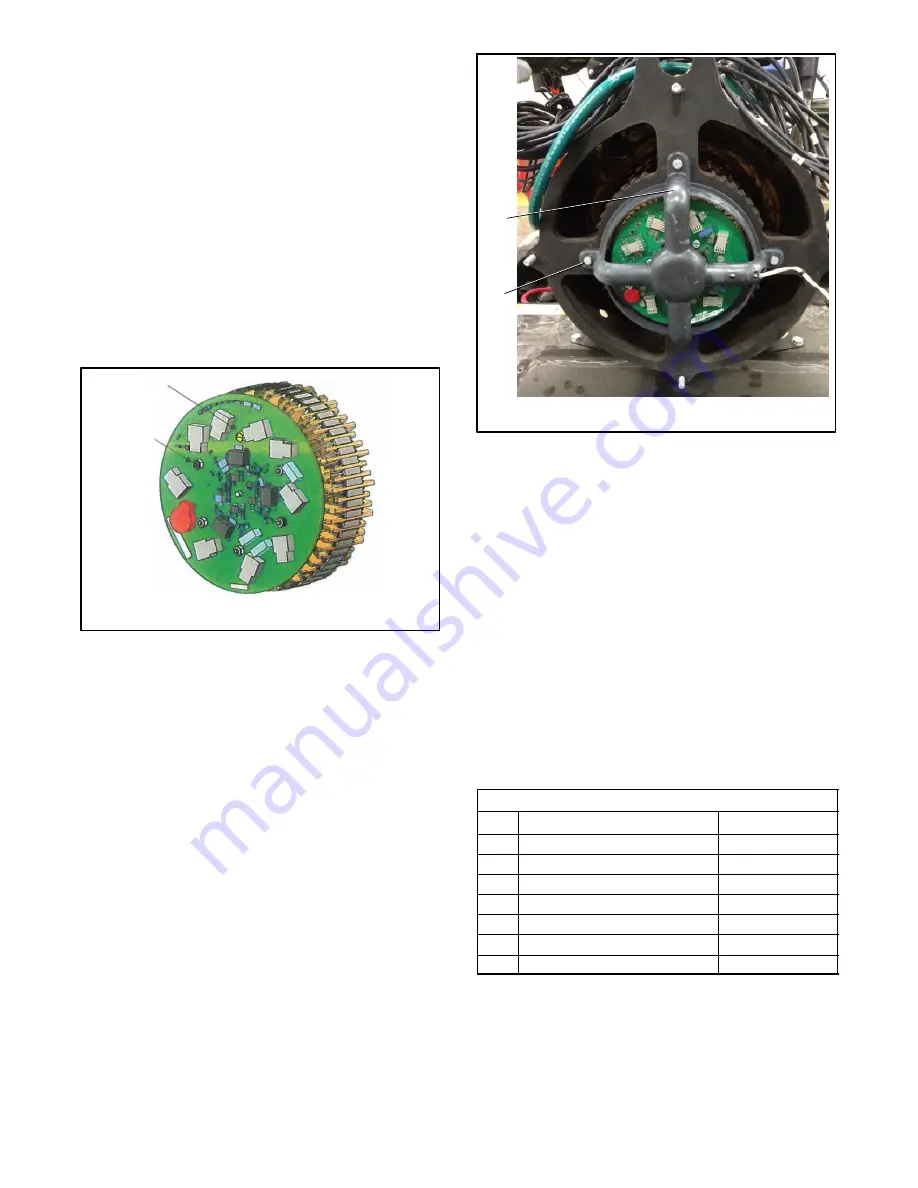
4.5 Secure the activator board (GM98939-1) to the
studs on the spacer by using 5 stainless steel
elastic stop hex nuts (M985-04-SS) and a
thread-forming screw (X-6071-8). Torque to 1.3
Nm (12 in. lbs.). See Figure 9 and Figure 11.
1
2
1. Thread-forming screw (X-6071-8)
2. Stainless steel nuts (M985-04-SS qty. 5)
Figure 9
Activator Board
4.6 Replace and tighten the 4 screws attaching the
LED optic board holder to the end bracket and
torque to 6.2 Nm (4.6 ft. lbs). See Figure 10.
SB-742
1. LED optic board holder
2. Screws (qty. 4)
1
2
Figure 10
Replacing LED Optic Board Holder
4.7 Install the alternator (rodent) guard to the end
bracket (if equipped).
4.8 Replace the junction box panels.
4.9 Replace the enclosure panels (if equipped).
5.
Restore the generator set to service.
5.1 Check that the generator set is OFF.
5.2 Reconnect the generator set engine starting
battery, the negative (--) lead last.
5.3 Reconnect power to the battery charger, if
equipped.
Parts List
Kit: GM101821-S
Qty. Description
Part Number
1
Spacer
GM98936
6
Screw, thread forming Torx head
M7500CE-05020-85
5
Terminal
X-283-58
5
Hex nuts, stainless steel
M934-04-SS
5
Nylock nuts, stainless steel
M985-04-SS
1
PCB activator board
GM98939-1
1
Screw, thread forming
X-6071-8
Summary of Contents for TT-1710
Page 6: ...6 TT 1710 6 17 Notes ...
Page 7: ...TT 1710 6 17 7 Notes ...


