background image

PRODUCT INFORMATION 


INDEX 


DATE 


Dep. 2 

IC-G-D-00-253e 


April 2016 


EMISSIONS PLATE OF EPA CERTIFIED ENGINES 


1/2


1.  ENGINE IDENTIFICATION PLATE 


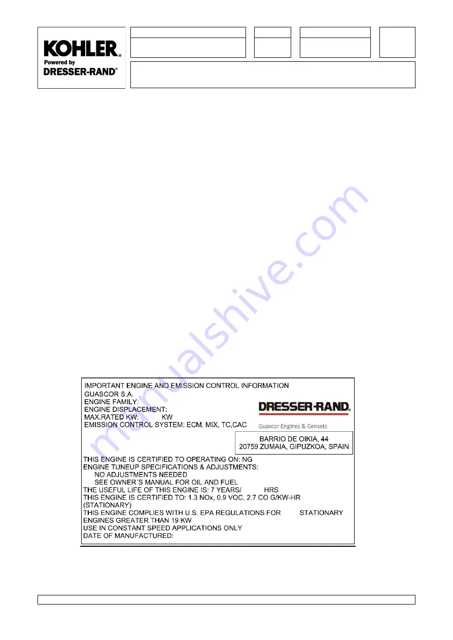
The  emissions  plate  of  the  engines  with  EPA  certification  under  40  CFR  part  60  subpart  JJJJ  includes  the 

following information: 


-  ENGINE FAMILY: EPA certification code corresponding to the engine model 
-  ENGINE DISPLACEMENT: in litres 
-  MAX.RATED  KW:  maximum  engine  power  (the  nominal  engine  power  except  for  Prime  applications 

where a 10% of overload is allowed, see conditions in IC-C-D-00-002e or in the engine thermal balance) 

-  EMISSION CONTROL SYSTEM: related to the engine configuration:  

o

  ECM Electronic Control Module for the electronic control of the carburation 

o

  MIX for the mixture of air and fuel by a carburetor 

o

  TC with turbocharger 

o

  CAC with Chargecooler. 

-  THIS ENGINE IS CERTIFIED TO OPERATING ON: indicates the fuel which the certification is valid for 

o

  NG (gas natural) 

-  THE  USEFUL  LIFE:  running  hours/years  (which  occurs  firts)  of  the  engine  emissions  certifications 

warranty. 

-  THIS ENGINE IS CERTIFIED TO: certified emissions values of pollutants. 
-  EPA certification year and manufacture year. 


On  the  180/240  in-line  engines  it  is  located  on  the  right-hand  side  of  the  crankcase;  on  the  360/480  and 

SFGLD/SFGM  560  V  engines,  the  plate  is  on  the  front  right-hand  side  of  the  crankcase,  and  on  the  HGM 

420/560 on the bottom right front panel of the water distribution box. 


Fig. 1 - EPA emissions Plate 


2.1.9

O&M_2.002211.810_A_10_2016

Summary of Contents for SFGLD360

Page 1: ...Engine Model SFGLD360 480 Gas Generator Set Models 750 1000REZK See Inside Front Cover for Service Assistance Information TP 6991 8 18b Engine Operation Maintenance...

Page 2: ...ee in the US and Canada 1 800 544 2444 D Outside the US and Canada call the nearest regional office Headquarters Europe Middle East Africa EMEA Kohler EMEA Headquarters Netherlands B V Kristallaan 1 4...

Page 3: ......

Page 4: ......

Page 5: ...does not exempt you from State or local air authority regulations In fact many State and local air authorities have adopted regulations more stringent than the EPA and will require on site testing to...

Page 6: ...ne FGLD SFGLD SFGM HGM engines 2 1 15 IC G D 00 151e Description of the components in one circuit V gas engines 2 1 17 IM G C 00 002e_F Gaps and wear limits for V Gas and Ethanol engines 2 1 25 IM G C...

Page 7: ...7 CHAPTER 4 OPERATING INSTRUCTIONS IT G A 00 011e_C Minimum room temperature for operating Gas engines 4 1 1 IO C M 15 002e_A Kohler Engine barring gear operating instructions 4 1 3 IO C M 20 001e_D...

Page 8: ...nder compression test 5 2 19 IO G M 33 001e_C Conventional spark plug changing and maintenance instructions 5 2 23 IO G M 33 002e_F Conventional spark plug replacement criteria in Gas engines 5 2 27 I...

Page 9: ...r KOHLER gas engines 1 1 IC G D 60 003e_D Review of compliance with european machinery safety regulations and CE mark requirements 1 9 IC G D 00 042e_E Sound pressure level in GAS engines 1 17 IC G D...

Page 10: ...receiving your Kohler engine They are part of the engine operation and maintenance manual we supply with each engine Therefore we recommend that the manual be kept in perfect condition and readily av...

Page 11: ...ised fuels such as natural gas landfill or digester gas should have another positive shut off valve manual automatic or valve train other than those in the carburettor or gas pressure regulation equip...

Page 12: ...off the supply of current Protect spark plugs wires and coils from the rain and snow 11 GENERATOR SETS DANGER The voltage produced by generator sets is dangerous for anyone who touches a part of the...

Page 13: ...tive methods for performing service and repair operations Some of these procedures require the use of specially designed tools Special tools should be used when and as recommended Anyone who uses a se...

Page 14: ...rbochargers or burns will result 16 ENGINE STORAGE CHEMICALS DANGER Protective oils contain a petroleum distillation which is harmful or fatal if swallowed Avoid contact with skin eyes and clothes Vap...

Page 15: ...lators and supply tanks to explode Oily and greasy materials must be kept away from oxygen valves hoses etc Oxygen if combined with such materials will cause and explosive reaction Always wear protect...

Page 16: ...with jump cables Batteries charged and discharged should be treated carefully when using jumper cables The following procedures assist in reducing sparks and explosion hazards always present in both...

Page 17: ...of pump or an inexpensive throw away pump Do not agitate acid solutions with compressed air Applications of acid should be followed by thorough rising then neutralising with an alkaline solution to re...

Page 18: ...le to eliminate these risks In this event Kohler informs users of any residual hazards due to the incomplete effectiveness of the protective measures advising them that they must have specific trainin...

Page 19: ...he moving parts of the engine to avoid any risk Therefore they incorporate guards or protective systems impeding physical contact that would cause injuries or accidents Drive components pulleys belts...

Page 20: ...e vibrations do not affect operator safety although they could be transmitted through the engine mounting to other machines or to the building causing a nuisance for people in the neighbourhood Engine...

Page 21: ...uble normally closed solenoid valve to stop the ethanol flow to the engine all in accordance with the specifications as required by regulation CONNECTIONS TO THE ENGINE in all cases by DIN flanges NPT...

Page 22: ...ontrols and although their primary function may not be to protect operators they do protect them indirectly by preventing malfunctions or inadequate operation The following information is legibly and...

Page 23: ...talling all the necessary peripherals for engine operation water oil fuel exhaust etc Specific installation instructions for each peripheral Specific instructions for engine complements or optional an...

Page 24: ...been designed in full awareness of and in compliance with the machinery safety regulations requirements as specified in Directive 2006 42 EC and the harmonised standards UNE EN ISO 12100 1 and UNE EN...

Page 25: ...und pressure Atmospheric pressure variations at one point produced by the propagation of a sound wave 3 NOISE EMISSION AT 1200 RPM The following table shows the sound pressure distribution in octave f...

Page 26: ...the engine running continuously at 1500 rpm and at 100 power F SFGLD SFGM ENGINES 180 240 360 480 560 LpA IN FREQUENCY BANDS Hz 125 250 500 1000 2000 4000 73 83 87 84 79 72 82 87 90 89 86 70 81 86 88...

Page 27: ...0 500 1000 2000 4000 76 88 91 87 83 70 86 84 89 87 83 74 90 85 87 82 70 84 84 88 89 83 73 87 85 87 91 86 LpA dB A 94 94 93 93 95 HGM ENGINES 240 420 560 LpA IN FREQUENCY BANDS Hz 125 250 500 1000 2000...

Page 28: ...ic pressure variations at one point produced by the propagation of a sound wave 3 NOISE EMISSION AT 1200 RPM The following table shows the sound pressure distribution in octave frequency bands and the...

Page 29: ...0 rpm and at 100 power F SFGLD SFGM ENGINES 180 240 360 480 560 LpA IN FREQUENCY BANDS Hz 63 125 250 500 1000 2000 4000 97 118 124 113 112 110 106 99 121 127 116 115 114 109 100 121 126 119 117 115 11...

Page 30: ...112 105 101 131 131 123 118 116 108 102 131 131 126 119 116 110 99 127 134 130 123 119 112 102 125 134 128 120 115 110 LpA dB A 132 135 135 136 135 HGM ENGINES 240 420 560 LpA IN FREQUENCY BANDS Hz 63...

Page 31: ...azardous waste see further below Only if it is planned to reuse the complete engine block is it admissible to keep it lubricated omitting to extract oil The area assigned to decontamination operations...

Page 32: ...s classified as hazardous waste which can be present in the machines at the end of their useful life and must be removed during the decontamination phase There are various methods available to remove...

Page 33: ...or removing oil from the filter consists in taking off and emptying the filter allowing oil to drain on the funnel of the collecting system or on a drip pan before squeezing the filter to facilitate d...

Page 34: ...abelling of Hazardous Waste Containers or packagings shall bear a firmly secured clear readable and indelible label stating the waste identification code nature of waste intrinsic hazards name and add...

Page 35: ...ainers by type of waste Those containers properly closed and tagged shall be stored in a sheltered area on an impermeable surface Applicable legislation defines the storage conditions Transport and di...

Page 36: ...commercial bolts nuts 2 1 37 IC C D 00 025e Units conversi n 2 1 41 2 2 Cooling System IT G A 20 025e One circuit cooling system for gas V engines 2 2 1 IT G A 20 007e_I Gas engines pressure losses a...

Page 37: ...TAND BY 2 2 2 7 Exhaust IC C D 40 003e_A Oxidative catalytic converters 2 7 1 IC G D 40 002e_B Exhaust system and ventilation of the oil sump 2 7 7 2 8 Starter IT C A 55 001e_J Electric starting 2 8 1...

Page 38: ...ng date On the 180 240 in line engines it is located on the right hand side of the crankcase See Fig 2 on the 360 480 and SFGLD SFGM 560 V engines the plate is on the front right hand side of the cran...

Page 39: ...FORMATION INDEX DATE Dep 1 IC G D 00 039e F January 2015 GAS ENGINES IDENTIFICATION PLATES AND CHARACTERISTICS 2 8 Fig 2 Identification Plate Location on 180 240 Series Engines 2 1 2 O M_2 002211 810_...

Page 40: ...RMATION INDEX DATE Dep 1 IC G D 00 039e F January 2015 GAS ENGINES IDENTIFICATION PLATES AND CHARACTERISTICS 3 8 Fig 3 Identification Plate Location on 360 480 560 Series Engines 2 1 3 O M_2 002211 81...

Page 41: ...INFORMATION INDEX DATE Dep 1 IC G D 00 039e F January 2015 GAS ENGINES IDENTIFICATION PLATES AND CHARACTERISTICS 4 8 Fig 4 Identification Plate Location on HGM 420 560 Engines 2 1 4 O M_2 002211 810_A...

Page 42: ...CTERISTICS PLATE The characteristics plate provides engine operating data including Firing order ignition timing valve adjustment auxiliary circuit temperature type of gas to be used and compression r...

Page 43: ...Dep 1 IC G D 00 039e F January 2015 GAS ENGINES IDENTIFICATION PLATES AND CHARACTERISTICS 6 8 Fig 7 Characteristics Plate 360 420 Series Engines Fig 8 Characteristics Plate 480 560 Series Engines 2 1...

Page 44: ...FORMATION INDEX DATE Dep 1 IC G D 00 039e F January 2015 GAS ENGINES IDENTIFICATION PLATES AND CHARACTERISTICS 7 8 Fig 9 Characteristics Plate Location on 180 240 Series Engines 2 1 7 O M_2 002211 810...

Page 45: ...TION INDEX DATE Dep 1 IC G D 00 039e F January 2015 GAS ENGINES IDENTIFICATION PLATES AND CHARACTERISTICS 8 8 Fig 10 Characteristics Plate Location on 360 420 480 560 Series Engines 2 1 8 O M_2 002211...

Page 46: ...nic Control Module for the electronic control of the carburation o MIX for the mixture of air and fuel by a carburetor o TC with turbocharger o CAC with Chargecooler THIS ENGINE IS CERTIFIED TO OPERAT...

Page 47: ...GLD180 continuous xGSRB24 0240 SFGLD240 continuous Prime xGSRB36 0360 SFGLD360 continuous Prime xGSRB48 0480 SFGLD480 continuous Prime xGSRB56 0560 SFGLD560 continuous xGSRB24 240E SFGLD240 Stand by x...

Page 48: ...gas mixture HGM engines supercharged by high compression ratio turbocharger and intercooler with lean burn technology Lambda 1 4 1 7 and low pressure air gas mixture Kohler engines can operate on gas...

Page 49: ...linder 2 intake and 2 exhaust which are formed by valve seats valves and valve guides as well as springs valve plates and half cones All the components fitted into the cylinder heads allow easy replac...

Page 50: ...y a double water circuit A main circuit which cools the motor crankcase cylinder heads and exhaust manifold except in the case of dry exhaust manifold as well as the air fuel mixture on engines with d...

Page 51: ...ressor and intercooler on a supercharged engine The intake manifolds are made from aluminium in In line engines from nodular casting in V engines and are provided with a safety explosion and pressure...

Page 52: ...5360 5450 11816 12015 5800 12787 General dimensions W mm in 1664 65 51 1664 65 51 1669 65 71 L mm in 2796 110 08 3033 119 41 3033 119 41 H mm in 2258 88 90 2278 89 69 2270 89 37 COOLING SYSTEM Types W...

Page 53: ...nual mechanical carburetion SFGLD SFGM Electronic ratio regulation and also manual regulation by adjusting screw Fuel gases Natural gas Digester Landfill Well gases A C Syngas A Propane B Natural gas...

Page 54: ...PRODUCT INFORMATION INDEX DATE Dep 8 IC G D 00 151e February 2015 DESCRIPTION OF THE COMPONENTS IN ONE CIRCUIT V GAS ENGINES 1 7 Fig 1 Right side view 2 1 17 O M_2 002211 810_A_10_2016...

Page 55: ...PRODUCT INFORMATION INDEX DATE Dep 8 IC G D 00 151e February 2015 DESCRIPTION OF THE COMPONENTS IN ONE CIRCUIT V GAS ENGINES 2 7 Fig 2 Left side view 2 1 18 O M_2 002211 810_A_10_2016...

Page 56: ...PRODUCT INFORMATION INDEX DATE Dep 8 IC G D 00 151e February 2015 DESCRIPTION OF THE COMPONENTS IN ONE CIRCUIT V GAS ENGINES 3 7 Fig 3 Top view 2 1 19 O M_2 002211 810_A_10_2016...

Page 57: ...PRODUCT INFORMATION INDEX DATE Dep 8 IC G D 00 151e February 2015 DESCRIPTION OF THE COMPONENTS IN ONE CIRCUIT V GAS ENGINES 4 7 Fig 4 Front view 2 1 20 O M_2 002211 810_A_10_2016...

Page 58: ...PRODUCT INFORMATION INDEX DATE Dep 8 IC G D 00 151e February 2015 DESCRIPTION OF THE COMPONENTS IN ONE CIRCUIT V GAS ENGINES 5 7 Fig 5 Rear view 2 1 21 O M_2 002211 810_A_10_2016...

Page 59: ...valve 15 Engine supports 16 Jacket water inlet 17 Jacket water outlet 18 Lifting eye 19 Exhaust gas outlet elbow 20 Oil cooler 21 Oil filters 22 Dipstick 23 Oil regulation and thermostat 24 Oil distr...

Page 60: ...SCRIPTION OF THE COMPONENTS IN ONE CIRCUIT V GAS ENGINES 7 7 41 Turbocharger 42 Air cooler drain 43 Water circuit drain 44 Lubrication pump 45 Wiring Box 220V 46 Wiring Box 24V 47 Oil filling plug 48...

Page 61: ...tween housing and lifter 0 006 to 0 044 Lifter guide 14 033 to 14 044 Clearance between lifter and rocker arm intake 0 3 Clearance between lifter and rocker arm exhaust 0 8 CYLINDER Liner inside top 1...

Page 62: ...3 9 Crankshaft journal 159 96 to 160 00 159 8 4 Crankshaft journal 1st crankshaft repair size 159 46 to 159 50 159 3 4 Crankshaft journal 2nd crankshaft repair size 158 96 to 159 00 158 8 4 Diametral...

Page 63: ...to 14 077 Clearance between housing and lifter 0 006 to 0 044 Lifter guide 14 033 to 14 044 Clearance between lifter and rocker arm intake 0 3 Clearance between lifter and rocker arm exhaust 0 8 SFGLD...

Page 64: ...nal 159 975 to 160 000 159 8 4 Crankshaft journal 1st crankshaft repair size 159 475 to 159 500 159 3 4 Crankshaft journal 2nd crankshaft repair size 158 975 to 159 000 158 8 4 Diametral gap between j...

Page 65: ...4 050 to 14 077 Clearance between housing and lifter 0 006 to 0 044 Lifter guide 14 033 to 14 044 Clearance between lifter and rocker arm intake 0 3 Clearance between lifter and rocker arm exhaust 0 5...

Page 66: ...ankshaft repair size 159 475 to 159 500 159 3 4 Crankshaft journal 2nd crankshaft repair size 158 975 to 159 000 158 8 4 Diametral gap between journal and bearing 0 120 to 0 204 Axial thrust disk thic...

Page 67: ...tions The counterweight bolts must be changed at each regrinding of the crankshaft The lips of the front and rear seals must be oriented towards the inside of the engine and impregnated with motor oil...

Page 68: ...head nut See IM C C 10 002e 48 471 Spark plug sleeve 23 226 Rocker arm adjusting screw 10 98 Valve lifter adjusting screw 4 5 44 SPARK PLUG See IO G M 33 001 IO G M 33 004 IO G M 33 007 DISTRIBUTION O...

Page 69: ...10 002e 48 471 Cyl head nut SFGLD SFGM 560 See IM C C 10 002e 45 441 Spark plug sleeve SFGM560 23 226 Rocker arm adjusting screw 10 98 Valve lifter adjusting nut 4 5 44 SPARK PLUG See IO G M 33 001 I...

Page 70: ...Cylinder head nut 48 441 Spark plug sleeve 23 226 Rocker arm adjusting screw 10 98 Valve lifter adjusting screw 4 5 44 SPARK PLUG See IO G M 33 001 IO G M 33 004 IO G M 33 007 DISTRIBUTION Oil pump g...

Page 71: ...cuments IM F C 00 002e and IM F C 00 004e for diesel and dual fuel engines and IM G C 00 001e for gas and ethanol engines 2 CALCULATING THE SCREW PRE STRESSING FORCE ACCORDING TO THE APPLIED TIGHTENIN...

Page 72: ...ossible to calculate the pre stressing force using this formula To determine whether a screw will resist a pre stressing force as calculated from a known tightening torque and coefficient of friction...

Page 73: ...er Loctite 243 will be used Screws that never need to be removed which fix low pressure oil or water pipes where gaps between threads are small Medium strength thread sealant Loctite 542 will be used...

Page 74: ...764 sq ft Volume 1 cubic in 16 387 cm3 c c 0 016387 dm3 liters 1 cm3 c c 0 061024 cu in 0 000035315 cu ft 0 00026417 gal 1 cubic ft 28 317 dm3 liters 0 028317 m3 1000 cm3 c c 1 dm3 liters 61 024 cu in...

Page 75: ...n HG in H2O kPa bar kg cm2 mmH2O 1 2 0360 27 68 6 8948 0 068948 0 070307 703 07 0 49115 1 13 595 3 3864 0 033864 0 034532 345 32 0 036127 0 073556 1 0 24909 0 0024909 0 00254 25 400 0 14504 0 2953 4 0...

Page 76: ...t the main cir the highest reheating pu g resistor PRODUCT INFOR T G A 20 ONE CIRC ing system a s used as th problems re gle cooling ci RAM cooling syst Figure 1 V e mp inder heads lator e engine of t...

Page 77: ...d haust manifo mp inlet for r on the degr ording to the 2 Jacket Wat RMATION 025e CUIT COOL ernal cooling lock where cooled exha olds water flo recirculation ree of dilatati water tempe ter cooling sy...

Page 78: ...NFOR T G A 20 ONE CIRC Jacket Water OLER CIRC gure 4 Tubu RMATION 025e CUIT COOL r cooling syst CUIT lar oilcooler INDEX LING SYST tem LEFT S and intercoo Sept TEM FOR SIDE VIEW oler DATE tember 2014...

Page 79: ...pipe P IT O F PRODUCT INFOR T G A 20 ONE CIRC igure 5 Plate RMATION 025e CUIT COOL es Oilcooler a 5 In 6 In 7 T INDEX LING SYST and intercoo ntercooler ntercooler ou Thermostatic Sept TEM FOR ler utle...

Page 80: ...d on the front left side of the engine Figure 6 Jacket water pump 1 Driven gear 2 Bearing 3 Seals 4 Impeller 3 2 OIL COOLER Lubrication and cooling oil cooling system 3 3 ENGINE BLOCK Distributes wate...

Page 81: ...l is needed as they control ranges from 8 to 10 C Electronic regulation is used for cases where precise temperature control is needed in heat recovery applications for example 3 6 1 CAJA DE TERMOSTATO...

Page 82: ...with a low w y valve that a rpressure pacity of at le be used in th with cooling air from colle s should be p inlet to the e e cooling circ e external co TEM ponsible for c ypes depen RMATION 025e CUI...

Page 83: ...nvironmental conditions The cooling circuit should be sized taking into account these variations as well as taking into account the fact that the cooling system may well get dirty KOHLER recommends ha...

Page 84: ...of the primary and or secondary cooling circuit s the minimum flowrates will vary The circuit s pressure loss Delta P and restriction K are valid for a basic engine configuration with mechanical pump...

Page 85: ...ate Delta P K rpm C m3 h bar FGLD180 1500 55 Biogas 15 0 42 1 86 10 3 55 0 45 2 01 10 3 80 0 46 2 04 10 3 1800 55 20 0 81 2 01 10 3 80 0 82 2 04 10 3 FGLD240 1500 55 Biogas 20 0 74 1 86 10 3 55 90 Mai...

Page 86: ...240 1200 25 0 21 3 3 10 4 1500 30 0 30 1800 40 0 53 SFGLD SFGRD SFGM 360 1200 40 0 16 1 0 10 4 1500 50 0 25 1800 60 0 36 SFGLD SFGRD SFGM 480 1200 50 0 28 1 1 10 4 1500 60 0 40 1800 80 0 70 SFGLD SFGR...

Page 87: ...0 55 20 0 76 1 89 10 3 80 0 64 1 61 10 3 1800 55 25 1 18 1 89 10 3 80 1 01 1 61 10 3 SFGLD360 1200 55 15 0 25 1 09 10 3 1500 40 55 90 Main C 20 0 44 1 09 10 3 55 120 Main C 0 45 1 13 10 3 80 90 Main C...

Page 88: ...1 29 SFGLD SFGRD SFGM 560 1200 55 17 0 6 1500 40 55 21 0 9 1800 55 25 1 28 4 MINIMUM FLOWRATES FOR HGM ENGINES 4 1 MAIN COOLING CIRCUIT Engine Speed Minimum Flowrate Delta P K rpm m3 h bar HGM240 1500...

Page 89: ...SFGLD SFGRD SFGM560 YES YES 7 Thermostats 5 2 AUXILIARY COOLING CIRCUIT SINGLE STAGE AIRCOOLER Engine Oil cooler Aircooler Thermostat Box FGLD180 YES YES YES 1 Thermostat FGLD180 Landfill Digester YES...

Page 90: ...19 20 C60 Thermostat Box HGM240 YES YES NO YES 4 Thermostats HGM420 YES NO YES YES 6 Thermostats Dist box HGM560 YES NO YES YES 6 Thermostats Dist box 5 4 2 Auxiliary Cooling Circuit Motor Oil cooler...

Page 91: ...lter valve Safety oil pressure switch Oil filters Jet pressure regulation valve Centrifugal filter diesel biogas low methane number gases and propane engines Blow by gas exhaust system crankcase breat...

Page 92: ...housed in a casing The design of the oil cooler can be adapted to the application requirements 2 7 CLOGGED FILTER VALVE Situated upstream of the filters this valve would divert oil to the sump in ord...

Page 93: ...e with a passive or an active blow by gas exhaust system 2 12 1 Open or passive system for diesel gas and ethanol engines The commonest standard blow by gas exhaust system is the open system with an o...

Page 94: ...e cooler Afterwards oil arrives at the filter access gallery where the clogged filter valve is to be found If for this reason filter clogging the pressure exceeds 6 bar oil will be diverted to the oil...

Page 95: ...reaching the crankshaft oil flows through internal channels which lead it to the bearing caps and big end bearings Oil circulates through ducts inside the connecting rod to reach the upper part of th...

Page 96: ...THERMOSTAT VALVE T 75 C YES NO NO PRES REG VALVE P 4 5 bar Distributor Low pressure switch CLOGGED FILTER VALVE P 6 bar OIL COOLER JET PRES VALVE P 3 bar Jets Piston head Turbocharge 1 2 Centrifugal...

Page 97: ...4 1 INTRODUCTION If engine driven equipment is intended for 24 hour operation or similar it is recommended that the engine should be fitted with an oil level controller Fig 1 General layout on 180 24...

Page 98: ...ngines generating sets 1 Automatic oil level controller 2 Oil tank 3 Filling hose 4 Oil sump to level controller hose 5 Venting hose 6 Lube oil level indicator Refer to IT C A 25 009e or IT G A 25 009...

Page 99: ...ring the position of the oil controller see enclosed table 1 Oil supply hose 2 Venting hose 3 Oil controller hose to oil sump 4 Height adjustment screw As the automatic filling equipment is connected...

Page 100: ...ine is running the oil level in the display must be within the normal operating range When the engine is stopped due to oil backflow in the circuit the oil level will exceed this range and overflow wi...

Page 101: ...adjustable switches It provides protection against the high and low level of lubricant caused by overfilling of water inside the sump Fig 1 General Layout 1 Lube oil level sesors box 2 High level ind...

Page 102: ...ce is to trigger a warning alarm when the level reaches the defined low or high limit Therefore the high and low oil limits will vary according to the oil capacity of the sump for each model of engine...

Page 103: ...gine running the oil level in the box must lie between the two defined limits This way in the event of oil overfilling due to a failure of the automatic supply system fuel or water ingress or oil leak...

Page 104: ...PRODUCT INFORMATION INDEX DATE Dep 2 IT C A 25 045e B September 2015 LUBE OIL LEVEL INDICATOR UL 4 4 Fig 5 Low level sensor signal Fig 6 High level sensor signal 2 3 14 O M_2 002211 810_A_10_2016...

Page 105: ...capacity there will be one two or four resistances See table 1 For heating oil we specify a 1500W resistance with a specific charge of up to 3 9W cm Fitting into the tank is with a 1 1 4 gas stamped b...

Page 106: ...420 560 4 180 240 400 V 50Hz 1500 W 1 360 480 2 SFGLD SFGM SFGRD 560 2 HGM 420 560 4 180 240 480 V 60Hz 1500 W 1 360 48 2 SFGLD SFGM SFGRD 560 2 HGM 420 560 4 Table 1 Oil Preheating System per Type of...

Page 107: ...ines 4 PERFORMANCE Warming expected from the proposed preheating system is 40 C over 2 hours 5 OPERATION Switching on off of the preheating resistances is through a control integrated into the engine...

Page 108: ...sion and fire hazards a polluted atmosphere harmful to the machine operators 2 CONFIGURATION A crankcase gas recirculation system CGR comprises the following parts A crankcase 1 which collects the gas...

Page 109: ...tering the crankcase will depend on the wear condition of the a m parts Due to crankshaft rotation and oil removal from different places in the engine an undetermined quantity of oil drops are carried...

Page 110: ...ankcase When the crankcase pressure does not coincide with the atmospheric pressure the dipstick will give a false reading as when crankcase pressure is negative it will indicate low oil levels and hi...

Page 111: ...m of the system there is a non return valve which prevents blow by gas from flowing in a direction opposite draining The device has marks on the top showing the gas flow direction by pointing to the i...

Page 112: ...pressure control valve this pipe transports the filtered gas to the engine air intake On gas engines the blow by gas feed pipe is connected between the air filters and the compressor Fig 1 2 3 and 4 2...

Page 113: ...ajor features of the controller Speed control variable duty and island applications Load control parallel mains applications Control of carburetion at different loads Control of carburetion for variat...

Page 114: ...lity variations do not exceed 10 Where gas quality is expected to change by more than 10 it is possible to feed EGS02 with the gas CH4 percentage to enable EGS to make the appropriate corrections 2 5...

Page 115: ...rom the teeth detection data EGS02 can calculate the engine rotational speed 3 2 MAT This NTC type temperature sensor reads the temperature of the air fuel gas mixture fed into the engine The data is...

Page 116: ...into the engine Controlling the throttle valve is the way the EGS can control the engine power or speed 3 5 TECJET This is a valve controlling the amount of gas supplied to the engine It incorporates...

Page 117: ...regulation the main adjuxsting screw is changed by an electronic gas control valve In the case of electronic regulation for the lambda close loop control regulation the zero pressure regulator and the...

Page 118: ...be installed with the outlet pressure adjusting spring facing up or facing downwards They require no inlet air pressure compensation line downstream of the filters fitting a compensation line could le...

Page 119: ...electronically controlled It requires a zero pressure regulator before Figure 4 Gas Control Valve 3 3 GAS CONTROL INJECTOR The gas control injector is a throttle valve powered by an electric actuator...

Page 120: ...ing which allows it to be mounted on the air intake manifold Complete carburettor Barrel Figure 6 Carburettor and barrel The operating principle is the Venturi effect As air flows through the barrel a...

Page 121: ...n permits easy adjustment of the proper air fuel mixture to ensure optimum operation of the engine under conditions of maximum efficiency or minimum exhaust emissions Figure 7 Air Gas mixteure by vent...

Page 122: ...rt up and idling but on load accuracy will be affected negatively At pressures greater than 275 mbar accuracy decreases as well and the error tolerance increases by about 10 in relation to the normal...

Page 123: ...lead to great variations in the carburetion of the engine For this reason we specify a maximum supply pressure to the Tecjet for Natural Gas and propane The graph below shows the maximum pressure requ...

Page 124: ...ure to the Tecjet 52 valve should not fluctuate in more than 2 mbar With the engine running at full power the position of the Tecjet52 valve must lie anywhere between 20 and 85 of its total travel In...

Page 125: ...GIS ignition unit models are used by Kohler GIS ignition unit GIS CSA ignition unit Both units have the same performance in operation The only difference of the two units lies in the housing 76 64 60...

Page 126: ...y incompatible items are the coil the high voltage lead and the ignition rails The electrical characteristics of the coil are different to those of the coil used with the CPU 95 electronic ignition sy...

Page 127: ...1 with 6 and 8 in line engines N 12 12V engines and N 8 16V engines D CAN communications cable for transmission of data from the module to the display E Communication with external equipment CAN or R...

Page 128: ...characteristics of each application All the data required such as distribution of ignition configuration of the energy parameters ignition sequence number of flywheel teeth etc are programmed at the...

Page 129: ...down The GPO General Purpose Output contact is totally configurable by software We can configure both those situations when we want it to be activated and the output logic itself With Kohler engines t...

Page 130: ...d out through the CAN port using the CANopen protocol NOTE The ignition module can be connected to the PC in two ways via the USB or RS 485 ports To activate said port please contact Kohler PC Connect...

Page 131: ...gue inputs 1 Configurable 4 20 mA 0 10 V Magnetic pick up 2 Hall effect pick up 1 Communications port 1 x USB 1 1 2 x CAN 2 0b 1 x RS 485 Display Optional GIS Unit Operating Temperature 40 C to 60 C D...

Page 132: ...nes Air Cooler only in supercharged engines Throttle Valve Intake Manifold 3 AIR FILTER It is the air filter s function to remove impurities from the air needed for combustion The most appropriate typ...

Page 133: ...tmospheric pressure carburettor next to the air filter and later the air fuel mixture is compressed From the turbocharger outlet the mixture passes through the air cooler to the elbow in the Throttle...

Page 134: ...rcuit at 55 C or 80 C depending on the engine model which circulates inside the tubes Two stage coolers have main circuit water flowing at 82 C through their first stage Water reduces the temperature...

Page 135: ...l internal ribs that cause the flow to go in the right direction In Line Engines The intake manifold lies on the left hand side of the engine and distributes the mixture to the cylinders V Engines The...

Page 136: ...ll mechanical air prefilters refer to document IC G D 35 001e In double stage filters this is how filtering occurs Air enters the filter tangentially to the cylindrical casing of the filter Passes thr...

Page 137: ...Fig 2 Exploded view of a tangentially sealed air filter Fig 3 Exploded view of a radially sealed air filter Fouling detector Air filter casing Safety filtering element Main filtering element Intake ca...

Page 138: ...g level the GHF filters have a mechanical airflow restriction detector Ref 76 50 319 with a red coloured indicator showing up completely when the maximum permissible pressure drop 38 mbar has been rea...

Page 139: ...FORMATION INDEX DATE Dep 2 IC C D 35 001e D September 2016 AIR FILTERS 4 4 Fig 6 Exploded view of Kohler High Flow one cartridge air filter FILTERING ELEMENT CASING CLAMP COVER 2 6 8 O M_2 002211 810_...

Page 140: ...the greater the efficiency obtained by the catalytic system depending on the pollutant being treated The appropriate permissible temperature range should be greater than 400 C and less than 600 C Thes...

Page 141: ...perated and maintained in accordance with the manufacturer s specifications Maximum inlet temperature to the catalytic converter 600 C Special lubricating oil with less than 0 6 weight of sulphated as...

Page 142: ...nverter depends on several factors such as the amount of contaminant available or the degree of efficiency of the catalytic converter but the temperature rise is normally below 40 C The temperature of...

Page 143: ...converter These curves show general tendencies for oxidative catalytic converters However noble or transition metals that make up the active stage as well as the coating material and the preparation m...

Page 144: ...mpounds entering the catalytic converter in the engine lubricating oil 5 TECHNICAL LIMITATIONS OF COMBUSTION GAS AND EXHAUST GAS As with the lubricating oil certain catalytic converter poisons can mix...

Page 145: ...ciency levels are regained DIRTYING OR MASKING The loss of activity by a catalytic converter through dirtying or masking happens when an inert residue or ash from the exhaust gases is deposited on the...

Page 146: ...T MANIFOLD Each exhaust manifold comprises various segments joined together The exhaust manifolds connect to the cylinder heads to receive the exhaust gases L engines The exhaust manifold lies on the...

Page 147: ...ocharger delivers high pressure air to the engine accordingly the amount of air the piston can take is greater This increase in the amount of air delivered allows the engine to increase its level of c...

Page 148: ...l combustion engines and where appropriate with a catalytic converter to reduce polluting emissions 6 CRANKCASE GAS BREATHER Crankcase ventilation aims to eliminate the combustion gases that enter the...

Page 149: ...PRODUCT INFORMATION INDEX DATE Dep 2 IC G D 40 002e B October 2010 EXHAUST SYSTEM AND VENTILATION OF THE OIL SUMP 4 4 Fig 3 Arrangement of Crankcase Gas Breather 2 7 10 O M_2 002211 810_A_10_2016...

Page 150: ...that moves linearly to engage with the flywheel gear The electric starter pinion is operated with a start button This pinion disengages as soon as the start button is released or when a tachometer rel...

Page 151: ...close as possible to the engine either in the terminal box or on the starter motor itself The system has a series of batteries to power the electric starter The standard batteries used by Kohler to st...

Page 152: ...rotation so that it can engage with the flywheel gear Rotation of the starter motor at maximum torque to start the engine Disengagement of the starter pinion from the flywheel gear after the engine h...

Page 153: ...pliance with the minimum or obligatory safety measures of the engine With a failure of this kind you should initiate a gradient shutdown of the engine With the 4 20mA analogue signals the control equi...

Page 154: ...e Engines 90 80 90 55 and 90 40 194 176 F 194 131 F y 194 104 F Main Circuit Outlet 4 20 mA 0 150 C 32 302 F 92 C 197 6 F Alarm or warning Always 96 C 204 8 F Emergency shutdown Always Water temperatu...

Page 155: ...044 psi Alarm or warning In operation Timed 5 sec Emergency shutdown Refer to Timed 5 sec Exhaust temperature After turbo 4 20 mA 0 800 C 32 1472 F T 50 C 122 F Alarm or warning T temperature balance...

Page 156: ...filter 4 20mA 50 50 mbar 0 73 0 73 psi 38 mbar 0 055 psi Alarm or warning Always Catalyst blockage SFGRD engines Catalyst inlet 4 20mA 50 50 mbar 0 73 0 73 psi 45 mbar 0 065 psi Alarm or warning Alway...

Page 157: ...80 90 55 and 90 40 194 176 F 194 131 F y 194 104 F Main Circuit Outlet 4 20 mA 0 150 C 32 302 F 92 C 197 6 F Linear power regulation 92 C 197 6 F 100 load 95 C 203 F 20 load Always Water temperature...

Page 158: ...OPERATION MAINTENANCE MANUAL SFGLD V KOHLER CO PRIME STAND BY 1 1 CHAPTER 3 HANDLING AND STORAGE INSTRUCTIONS IM G C 00 004e_A Lifting system for SFGLD SFGM V engine 3 1 1 IO C M 00 001e_A Deferred st...

Page 159: ...n and that it can bear the weight of the engine plus 10 If you are not sure weight the engine before raising it The use of cloth slings is recommended in order to prevent damage to the engine with sha...

Page 160: ...on crane and in place ne 1 970 mm ne 2 300 mm OF ENGIN he end of the friction ding EQUIPMENT he front sling g PRO IM beams with m in total m in total NE e front sling to T PROCES comprises ODUCT INFOR...

Page 161: ...GINE e hook open EQUIPMENT e two rear slin PRO IM other eyebo E n in the two PROCESSES ngs between ODUCT INFORMA G C 00 0 LIFTING olt eyebolts the gas reci ATION 004e G SYSTEM irculation pip INDEX A F...

Page 162: ...Exercise ca f the slings w ed on lifting ODUCT INFORMA G C 00 0 LIFTING each side of t preassemble aution with th with a shackle ATION 004e G SYSTEM the engine ed fork and h he recirculati e as per t...

Page 163: ...PRO IM PROCESSES king care not ODUCT INFORMA G C 00 0 LIFTING t to cause an ATION 004e G SYSTEM ny friction or r INDEX A FOR SFG rubbing agai Mar GLD SFGM nst the engin DATE rch 2016 M V ENGIN ne comp...

Page 164: ...date of dispatch from factory with Kohler Basic Warranty remaining valid The total storage and warranty period shall by no means exceed 42 months from the date the equipment is at the customer s dispo...

Page 165: ...Workshop shall recommend that Customer should start the engine periodically weekly and operate it at least for one hour idling or on low load In addition to the items described in this Product Informa...

Page 166: ...on the condition of the equipment Check the water pumps of the engine to determine whether they rotate freely and their belts in the case of belt driven pumps are in good condition If you observed any...

Page 167: ...ng Put all leads and cables in plastic bags Also apply TECTYL 506 or any similar substance to any components showing signs of rust damage 7 PACKING OF DEFERRED START UP ENGINES These instructions appl...

Page 168: ...PRODUCT INFORMATION INDEX DATE Dep 1 IO C M 00 001e A December 2007 DEFERRED START UP ENGINE INSPECTION AND PROTECTION 5 6 3 1 11 O M_2 002211 810_A_10_2016...

Page 169: ...PRODUCT INFORMATION INDEX DATE Dep 1 IO C M 00 001e A December 2007 DEFERRED START UP ENGINE INSPECTION AND PROTECTION 6 6 3 1 12 O M_2 002211 810_A_10_2016...

Page 170: ...ed and ethanol engines 4 1 11 IC G D 30 001e_D Fuel specifications for Gas engines General 4 1 13 IC G D 30 021e_B Fuel specifications Us natural gas 4 1 19 IO G M 33 010e Installation and operation m...

Page 171: ...indicated You should take into account the Criteria for application of pre lubrication post lubrication and oil and water pre heating described in document IC C D 00 008e For lower room temperatures...

Page 172: ...ge the supply scope of these engines out of standard If the fuel gas has a high concentration of moisture or heavy hydrocarbons like usually have biogases syngases or well gas the minimum temperature...

Page 173: ...n engages the ring gear 4 Rotate the socket to turn the flywheel 5 Upon completion of the maintenance operations replace the barring gear cover NEVER TRY TO START THE ENGINE WITH THE SOCKET CONNECTED...

Page 174: ...aeration Low deposits Bacterial Sulphate reducing bacteria ferrobacteria nitrifying bacteria denitrifying bacteria Cavitation Cavitation is the creation of bubbles within a liquid when it passes throu...

Page 175: ...and decreasing the flow rate which in turn results in an increase in temperature Both observing the colour feel and smell of sludge and analysing it will provide information about its origin 2 COOLING...

Page 176: ...s logarithmic and inverse any increase in pH by one unit corresponds to a tenfold decrease in the hydrogen ion molar concentration The lower end of the scale pH 0 defines the acidity equivalent to a s...

Page 177: ...The best way of avoiding problems due to corrosion oxidation scale deposits etc in the cooling system is to treat water with adequate additives which will protect the metallic surfaces of the system...

Page 178: ...nt temperatures being very low and there is a risk of freezing the maximum permitted amount of glycol and for use only in engines is 50 The use of incorrect quantities of antifreeze in the cooling cir...

Page 179: ...d using fresh water Once rinsed and clean immediately fill the water circuit with treated antifreeze In open systems that operate on large volumes of water water treatment is very expensive Input trea...

Page 180: ...ngs liners and valve seats All this means the oil has a long service life and filters withstand extended maintenance intervals Given its advanced formulation KOHLER MOTOROIL 3040 PLUS is specially sui...

Page 181: ...ecautions are required for its use except good personal hygiene and avoiding contact with the skin for extended periods of time There is a Safety Data Sheet available on request TYPICAL CHARACTERISTIC...

Page 182: ...vice life of the engine Depending on the type of constituents to be completely or partly eliminated from the gas so as to adjust their concentration to the specifications one of several filtering tech...

Page 183: ...the right to carry out its own analysis on fuel gas fed to the engine 4 CONTAMINANTS AND FACTORS AFFECTING THE ENGINE OPERATION The fuel gas contaminants and factors affecting the engine operation fal...

Page 184: ...9600 22250 kcal mn 3 See IC G D 30 038 PROPANE 93 100 MJ mn 3 equal to 22200 23900 kcal mn 3 See IC G D 30 018 5 2 CONTAMINANTS OF FUEL GAS Listed below are the contaminants that are normally found in...

Page 185: ...ey contain into silicon dioxide silicates and other crystalline compounds that precipitate forming abrasive particles inside the engine and jamming valves pistons and other parts essential to the oper...

Page 186: ...a relative measure of the quantities of contaminants that may show up in a fuel gas fed to the engine Lubricating oil is one of the engine consumables that permit to rapidly notice a deterioration of...

Page 187: ...tion of the place where the analysis is conducted within an installation or at a location 2 Date time of sampling 3 Date time of analysis 4 Analysis procedures employed 5 Gas temperature and pressure...

Page 188: ...the engine is equipped with refer to the following Product Information documents for the applicable ranges IC G D 30 007e Engines with a TECJET 50 type electronic carburetion system IC G D 30 040e Eng...

Page 189: ...Br I STATED AS Cl HF and HCl are the most harmful acids therefore their concentration is specified in mg of Cl equivalent mn 3 and the remaining constituents are considered as if they were chlorine us...

Page 190: ...s is set at 60 ppm 45 mg mn 3 2 4 5 RESIDUAL OILS AND TAR Condensation is not allowed Consult Kohler about analysis methods 2 4 6 SOLID PARTICLES Kohler has established the following limits in connect...

Page 191: ...nes Recommended O2 Oxygen in gas 2 vol Mechanical carburetion Readjust carburetion 1 carb point O2 Oxygen in gas 2 vol Electronic carburetion Continuous methane meter for automatic setting of carburet...

Page 192: ...DISPLAY CONFIGURATION Configuration is divided into two steps In order to connect the ignition unit to the display first you have to configure the unit Screen configuration For both steps you have to...

Page 193: ...n this case choose the MIC4 option 3 The node number must be entered All KOHLER GIS units have Node ID 30 set as default After completing these steps press the Save button to save the settings on the...

Page 194: ...nguage Adjusting the date and time Click the Set button and change the date and time Screen calibration If the touch screen is not responding properly to touch click the Display Calibration button The...

Page 195: ...cess level several options are at your disposal Login Logout Login Logout to a specific operating level with the access level selected Change Pin Change PIN access code This can only be accessed at Ma...

Page 196: ...ts Ignition timing adjustments Self Test Operating hours adjustment Spark plug operating hours adjustment Master Service rights Enabling Disabling access control Reset all PINs Firmware update 3 USE O...

Page 197: ...here are misfires Further details on the information this led provides can be found in the Ignition view Ignition Enabled This LED indicates whether the ignition unit has received a spark enabled comm...

Page 198: ...ays the external correction the unit receives via communications CAN Modbus This timing correction can come from several devices o From the display itself o From the PLC that controls the engine o Fro...

Page 199: ...k in the spark plug gap Misfire Indicator This LED gives information on where the misfires have occurred in the different cylinders o Grey There are no misfires o Yellow has previously been misfiring...

Page 200: ...of energy parameters 3 1 5 Firing Angle This view displays the individual timings per cylinder Fig 11 Screenshot of ignition timing per cylinder 3 1 6 Message Log This view displays a record of al ala...

Page 201: ...ed number Cycle signal missing Cam signal was not detected in time More events were counted than expected per cycle Trigger period Event period between two teeth was outside the expected range Reset n...

Page 202: ...r trigger missing Event period of pre processor pickup is outside the expected range Pre processor pickup Index missing The pre processor pickup has not been able to detect the reset cam signal Pre pr...

Page 203: ...creenshot of device information 3 1 8 Diagnostics This view includes further information on unit operation board temperature voltage Fig 16 Screenshot of the unit s operating parameters 3 2 ADJUSTING...

Page 204: ...ignition timing You can adjust the ignition timing on the next screen Adjustments can be made in increments of 0 1 o 0 5 Fig 14 Adjusting the ignition timing 3 2 2 Adjusting energy parameters Both th...

Page 205: ...ecommends that you do not change the energy parameters previously configured in the ignition unit Changing these can cause an engine malfunction 3 2 3 Operational hours The spark plug burn time durati...

Page 206: ...re that there are no oil fuel or coolant leaks on all joined surfaces Refrigeration engine coolant circuit Check the coolant level and concentration Add additional quantity if necessary If the amount...

Page 207: ...operations when the engine is running with no load or a very light load 3 PRECAUTIONS TO BE TAKEN AT EACH START UP The procedure for starting up an engine is described below 3 1 Before engine start up...

Page 208: ...portant aspects which must be checked while the engine is in operation Examine the water fuel and oil conduits in case of leaks mechanical damage or corrosion Inspect the level and status of coolant T...

Page 209: ...ocedure shall be as follows 1 Turn the fuel supply to the engine off 2 Allow the engine to turn over several times and then disconnect the ignition system Any residual fuel will get out of the system...

Page 210: ...arburation is adjusted so that the specified NOx level is complied with in each case Normally the NOx value is related to 5 Oxygen provided the applicable legislation does not specify another referenc...

Page 211: ...on of a wire failure of the ignition unit It is associated with a high level of Total Hydrocarbons THC if measured Also the exhaust temperatures will be lower on the affected cylinder bank and possibl...

Page 212: ...nditions Legislations use to indicate the reference conditions to be taken In general normal conditions 0 C and 1013 mbar 100 KPa are the usual reference Below are bases of unit conversion for a numbe...

Page 213: ...ts it is a wet basis concentration value The emission value in ppm used in the formulae must be a wet basis value usually NOx SO2 and CO are measured in dry basis and the calculation of NOx requires c...

Page 214: ...50 0 Weighting Factor 0 15 0 15 0 15 0 1 0 1 0 1 0 1 0 15 D1 Cycle Speed Rated Speed Torque 100 75 50 Weighting Factor 0 3 0 5 0 2 D2 Cycle Speed Rated Speed Torque 100 75 50 25 10 Weighting Factor 0...

Page 215: ...l as the level can be checked without having to stop the equipment When the float hits the high or low limit switch it activates the alarm on the equipment Fig 1 Oil level indicator 1 Oil level indica...

Page 216: ...unt of oil in the equipment was above or below the permissible limits due to obstruction in the pipe that connects the oil level indicator to the oil sump in the engine Cleaning the oil level indicato...

Page 217: ...h opens or closes the oil flow into the engine crankcase based on the oil level in the oil sump at that time KOHLER engines do not use this latter function of the actuator since they incorporate anoth...

Page 218: ...m the oil circuit causing overfills However after restarting the engine the oil level will lie again in the normal range 2 MAINTENANCE Cleaning the controller indicator and checking correct operation...

Page 219: ...levels the maintenance schedule for each application and engine configuration must be followed Failing to follow these instructions when installing a certified engine in a piece of non road equipment...

Page 220: ...peline must be laid for each engine individually Never put together the gas outlets of various engines in a single collector For completion of the exhaust pipeline there must be a condensate trap inst...

Page 221: ...engine exhaust connections for V engines are given in IT G A 40 002e In line engines don t require special connections 3 INSTRUCTIONS FOR INSTALLATION OF THE FUEL PIPE In order to control emissions ef...

Page 222: ...from the point of entry to the sources of heat in its circulation towards the point of exit The expulsion of hot air should be at a point directly above the most important sources of heat avoiding th...

Page 223: ...eters and the alarm logic operation 7 IN USE TESTING The U S EPA certification regulations for LSI engines require the engine manufacturer Dresser Rand A Siemens Business to notify the equipment manuf...

Page 224: ...ase gas breather 5 2 17 IO C M 00 006e_A engine cylinder compression test 5 2 19 IO G M 33 001e_C Conventional spark plug changing and maintenance instructions 5 2 23 IO G M 33 002e_F Conventional spa...

Page 225: ...this section do not in any way imply an obligation on behalf of Kohler and are given only as a guide to users for maintenance scheduling Users must take into account operating conditions and demands...

Page 226: ...spheric pressure Therefore the oil level must be checked when crankcase pressure is at atmospheric pressure or the reading must be done in the devices not influenced by these pressure differences lubr...

Page 227: ...ing could lead to serious damage GAS LEAKS 2 8 Inspect gas piping for leaks using a gas detector or water with soap Tighten hardware or change gaskets if necessary NEVER USE A FLAME TO DETECT GAS LEAK...

Page 228: ...re given only as a guide to use rs for mai ntenance scheduling Users will take into account op erating conditions and demands to determine the maintenance operations that should be carried out more fr...

Page 229: ...N1 100 h Operations after starting up or break in phase Change oil KOHLER MOTOROIL oil sump and cooler Change oil filters Analyze waste oil Clean the oil centrifuge filter and change the paper filter...

Page 230: ...with the pre heater if necessary Check the oil level of the pneumatic starter lubricator if necessary Clean the engine and its surrounding Operations to be carried out with the engine idling Check oi...

Page 231: ...level Check battery and starter connections Inspection of high voltage wires of the ignition system Change the filter of crankcase gases recirculation system and clean this circuit A E3 4 800 h or onc...

Page 232: ...em Clean pipe bundles and change gaskets on heat exchanger and coolers Change oil thermostat only V engine Test thermostats of coolant circuit Clean filters of coolant circuit Change filter cartridge...

Page 233: ...k number of retightenings on the bolt Change thermostats of coolant circuit Recondition water pumps of main coolant circuit R3 44 800 h Engine Overhaul including its major components and systems Inspe...

Page 234: ...riable it s recommended to reduce the periods between carburetion adjustments A Make this maintenance job only if the engine has crankcase gases recirculation system 2 ENGINE LONG TERM STORAGE When a...

Page 235: ...Users will take into account op erating conditions and demands to determine the maintenance operations that should be carried out more frequently than stated on the schedule In all cases the number of...

Page 236: ...E Type E Minor Jobs Job Interval Job Description ED 24 h Check oil pressure and temperature during the pre lubrication phase Verify oil heating with the pre heater Check battery acid level Verify wate...

Page 237: ...lized Check coolant level pressure Vent circuits Check oil level pressure Inspect the air filter plugging level Check oil and coolant temperature Check exhaust gases temperature Record engine paramete...

Page 238: ...spection of high voltage wires of the ignition system Change the filter of crankcase gases recirculation system and clean this circuit A E2 1 500 h or 3 years Check gas filters Change hoses and clamps...

Page 239: ...gaskets on heat exchanger and coolers Change thermostats of oil only V engine Change thermostats of coolant circuit Clean filters of coolant circuit Change filter cartridge Retighten connections in k...

Page 240: ...ble it s recommended to reduce the periods between carburetion adjustments A Make this maintenance job only if the engine has crankcase gases recirculation system 2 ENGINE LONG TERM STORAGE When a cus...

Page 241: ...ibes the oil sampling procedure for its subsequent analysis while document IO C M 25 004e deals with the oil change procedure NOTE Changing oil from an engine does not only consist in draining the cra...

Page 242: ...d oil change frequency prevents reaching the point where oil can no longer accept any increase in contaminants TBN It is the function of the alkaline additives contained in oil to neutralize the acidi...

Page 243: ...ystem Both sodium silicate and potassium metaborate are typical inhibitors and responsible for introducing Si K or N and B into oil Another way of detecting the presence of coolant consists in determi...

Page 244: ...s of acceptability of an oil for natural gas biogas or biomass gas engines have been established from a database obtained through the use of the lubricant in real operating conditions and tests of was...

Page 245: ...oil change but bear in mind that you should not take samples at the beginning or end of the oil sump draining process To take samples for analysing the oil condition when there is a sampling valve uni...

Page 246: ...ons for each type of engine and application or when the values of the tested parameters have reached their maximum permissible limits as specified in the oil maintenance instructions in respect of eac...

Page 247: ...maximum and minimum marks on the dipstick 7 Inspect for possible oil leakage in the engine 8 Check the oil level every day With the engine at rest and cold oil the level must reach the maximum mark o...

Page 248: ...value To dismount the filter 1 unscrew the filter body with your hand or with the special purpose spanner 2 make sure the old gasket comes out with the filter cartridge Mounting the filter 1 Oil the g...

Page 249: ...and clean the interior of the rotor with a cloth Put a new filtering paper 7 1 5 Clean the nozzle with a bronze wire to verify that oil can circulate freely Make sure that the inside of the shaft is u...

Page 250: ...ence Check to see that with the cartridge you receive one O ring for the top of the filter cartridge and another for the upper part of the body 1 1 Changing the filtering cartridge Release the 4 filte...

Page 251: ...refore we recommend removing its operating lever 1 Crankcase 4 Pressure control valve 2 Blow by gas breather 5 Oil return line 3 Gas recirculation filter 6 Connecting hoses The graph below shows the c...

Page 252: ...by gas and the exhausted quantity may denote the occurrence of a failure The following table shows the relation between the crankcase pressure and the engine components suggesting corrective actions C...

Page 253: ...t preventer eliminating all accumulated dirt and residues If the wire mesh is badly damaged change it 2 Clean bodies n 1 5 and check to see if the O rings n 2 8 are in perfect condition flexible and f...

Page 254: ...cket gas FV engines remove the full gas vent and follow the instructions in point 1 to open it and then clean the metal mesh following the instructions in point 2 Photo 1 Crankcase Gas Breather Once t...

Page 255: ...gnition 2 TEST PROCEDURE Before starting the test make sure the engine is warm and Diesel and Dual Fuel Engines all the injection pipes are loose and all the rocker covers removed thus preventing the...

Page 256: ...ed Press the discharge valve of the pressure gauge until the pointer indicates zero Test the remaining cylinders similarly in correlative order ATTENTION The table below shows compression test values...

Page 257: ...al speed is similar during the test 3 CONDITIONS CAUSING LOW ENGINE COMPRESSION The following conditions principally can cause low engine compression Scratched liner which also implies high oil consum...

Page 258: ...proper operation You can measure and adjust only some of the Kohler referenced spark plugs In particular the spark gap will be measured against the values tabulated below using thickness gauges in th...

Page 259: ...al dirt from the surface of this portion using an absorbent paper You can start screwing on the spark plugs manually making sure the washer is correctly placed in its seat Finally use the torque wrenc...

Page 260: ...SITS OF CALCIUM OR BARIUM These elements normally proceed from oil but calcium also exists in water 7 Hard whitish deposits on the spark plug DEPOSITS OF BURNT OIL Possible wear or scratching of cyl l...

Page 261: ...determine when the spark plugs fail The spark plug reference voltage value has an initial value which basically depends on the coil used but may also vary according to the types of wires and spark plu...

Page 262: ...NO SEC SPARK Maximum CAVG EAVG difference 15 Maximum EAVG CAVG difference 15 The remaining values that refer to changes in energy levels are not necessary since the system does not use them 4 USE OF T...

Page 263: ...dary voltage value in a cylinder is very high or very low this may mean an ignition failure in some cases a spark plug failure Fig 2 Secondary voltage values on the GCS unit screen 6 USE OF EXHAUST TE...

Page 264: ...types of grease include Dow Corning DC 4 G E G 623 or GC Electronics Z5 Also apply a small amount of grease onto the wire connector and coil 2 You can measure and adjust the spark plug gap of some of...

Page 265: ...mpulse The coil is a component of the engine that barely needs any maintenance In case of failure it is necessary to change the coil for a new one since it is beyond repair Checking consists in measur...

Page 266: ...h voltage wire from the coil and the high voltage wire to the spark plug must be perfect During the inspection according to the maintenance guidelines check the following before fitting new wires into...

Page 267: ...as a guide to the servicing needs According to the operating conditions requirements and fuel properties user has to define whether replacing the spark plugs is necessary before or after the working t...

Page 268: ...00 IO G M 00 024 1600 IO G M 00 035 SFGLD natural gas LCR 8 1 ISLAND 2500 IO G M 00 079 2000 IO G M 00 078 SFGLD syngas 800 IO G M 00 042 700 IO G M 00 003 600 IO G M 00 043 4000 3500 3000 SFGRD natur...

Page 269: ...cases the strobe timing gun cables are laid over the engine In order to avoid any risk due to moving parts the strobe gun cables should not be passed from one side to the other with the engine runnin...

Page 270: ...inal 4 Start engine and go to the operating point chosen to measure the ignition timing 5 Connect to the terminal of the battery to make the strobe gun work Image 3 Red clamp on positive terminal of t...

Page 271: ...t the gun earth to the ignition rail engine block or coil earth 2 Stand on an insulated stool wearing a high voltage glove and helmet with electrical protection screen connect the clamp to the seconda...

Page 272: ...the cylinder 1 rocker arm loosen the ball joint nut 2 and the rocker arm ball joint 3 until the rocker arm 1 moves freely see figure 1 on page 2 3 Loosen the valve lifter lock nut 6 and adjusting scr...

Page 273: ...ENT OF GAS AND ETHANOL ENGINE VALVES VALVE CLEARANCE 2 4 8 8 6 7 4 3 5 1 2 Fig 1 Valve Adjustment 1 Rocker arm 2 Ball joint nut 3 Rocker arm ball joint 4 Rocker arm pushrod 5 Valve lifter 6 Valve lift...

Page 274: ...ll cases when both valves of one cylinder are depressed open crossing stroke the valves of the paired cylinder are released closed on compression stroke and can be adjusted 1 2 0 120 PMS PMS 10 9 3 4...

Page 275: ...he reference value is the initial measurement after 100 hours of operation of the cylinder head If this value increases over time by more than 1 mm the wear should be carefully monitored If this value...

Page 276: ...n or pressure loss is 38 mbar and it is measured with the engine running at rated power and load For monitoring their fouling level the Kohler engines double stage filters include either a mechanical...

Page 277: ...specified by the maintenance programme see point 2 2 Fig 1 Exploded view of a tangentially sealed air filter For radially sealed filters inspecting the main filtering cartridge will imply the followi...

Page 278: ...cartridge and cleaning or changing the filter if necessary or specified by the maintenance programme reassemble the filter proceeding in reverse order of its disassembly 3 Reset the mechanical fouling...

Page 279: ...air filters must take place with the engine at rest in a ventilated room following these instructions 1 For tangentially sealed filters back off the air filter locknut and remove the front sealing ri...

Page 280: ...ondition of the filters by means of a light signal or by transmitting an electric signal to the PLC Always service the GHF filter i e replace the two filtering cartridges with the engine at rest 3 1 C...

Page 281: ...ERS MAINTENANCE 6 6 Fig 3 Exploded view of Kohler High Flow two cartridge air filter Fig 4 Exploded view of Kohler High Flow one cartridge air filter COVER CLAMP CASING FOULING DETECTOR FILTERING CART...

Page 282: ...rete jumps of temperature The self adhesive indicator has ten graduations between the two temperature limits that in our case are fixed at 71 C and 110 C When the temperature reaches or exceeds a refe...

Page 283: ...ust only be changed when the schedule program sets it It is recommended to place the damper so that both filling plugs are roughly in a horizontal position and to leave it in that position for at leas...

Page 284: ...container Immediately replace the filling plug and torque to 2 5kg 18lb ft and seal it with a punch mark It is advisable to insert a new O ring included in the kit and to tighten the plug until match...

Page 285: ...completely clean and free from impurities Intermediate Condition The sample has a lightly darkened color and may contained particles Critical Condition The sample has a dark brown or black color and...

Page 286: ...rcuit is located in the thermostat housing or on the inlet pipe to the latter If there is no thermostat housing look for it at the highest point of the circuit In general for the auxiliary circuit it...

Page 287: ...ins to flow out with no air at which point you have to close the valve without forgetting to refit the automatic bleed valves and open said shut off valve Fig 3 Automatic air bleed valve It is in turn...

Page 288: ...ydrometer is used to determine the concentration of glycol in the water which will give the density of the water antifreeze mixture The supplier of the antifreeze is required to provide the table that...

Page 289: ...heck whether water still comes out Then close all the bleed valves Since antifreeze is a pollutant it must be collected in a suitable container for subsequent treatment or reuse To fully drain the dry...

Page 290: ...t has been dampened They are then rinsed with plenty of water until no further deposit exits The water seals have to be changed before assembling the intercooler Cleaning can be done using high pressu...

Page 291: ...orce axially on the shaft and check that there is no axial clearance Check for radial play Apply force radially on the shaft and check that there is no radial clearance Rotation Push one of the wheels...

Page 292: ...for proper operation if your engine comes with a pre lubrication system you can use it Once you have finished the inspection refit the drainage tube Lubricate the new turbos before starting them To d...

Page 293: ...Dip the components in a container with a solvent e g trichloroethylene until they are free from grease or oil residues Neutral household soap can be used instead of solvent provided it has no chemica...

Page 294: ...compressor wheel or turbine wheel with their respective casing Incorrect play may result from damaged axial bearings that permit shaft movements beyond normal limits Damage to the bearings can origina...

Page 295: ...fire as it catches Finally an O ring gasket seals the whole unit during the normal operation of the engine 2 2 INSPECTION GUIDE 1 Intake safety valves shall be visually inspected on a regular basis d...

Page 296: ...with dust they must be cleaned with non corrosive non flammable products 2 The O ring may deteriorate due to ageing and chemical attacks leading to gas escape On detecting gas leaks change the valve...

Page 297: ...cally implies cleaning the set of plates cleaning the water pipes plugging the water pipes Different intercooler models 2 1 Cleaning the set of plates Excessive dirt build up on the plate surface redu...

Page 298: ...lates Finally reassemble the cooling core as explained in section 4 2 2 Cleaning the water pipes For chemical cleaning of the water pipes inside it is not necessary to remove the intercooler from the...

Page 299: ...rs from the intercooler taking care not to damage the surface of the gaskets 4 FITTING THE INTERCOOLER Here is the procedure for fitting the intercooler Check and clean the seals contact areas Change...

Page 300: ...Cleaning the pick up wipe the pick up head with a damp cloth to remove sticking dirt Do not use any solvent or other aggressive products that would damage this device Also clean any waste oil dust etc...

Page 301: ...es Otherwise the battery needs recharging section 2 2 NEVER PUT A FLAME OR MAKE SPARKS NEAR A BATTERY FLAMMABLE VAPOURS COULD BE ISSUING 2 2 CHARGING THE BATTERY Do not charge a battery if the room te...

Page 302: ...r putting the battery in service again recheck the acid level and adjust to the maximum level identified on the battery with a line or mark 2 4 CHANGING THE BATTERY Detach the clips from the terminals...

Page 303: ..._A 10 2016 INDEX Chapter 6 TROUBLESHOOTING OPERATION MAINTENANCE MANUAL SFGLD V KOHLER CO PRIME STAND BY 1 1 CHAPTER 6 TROUBLESHOOTING IO G T 00 001e_B Gas engines troubleshooting 6 1 1 O M_2 002211 8...

Page 304: ...d gasket 3 Change head 4 Change liner 5 Repair crack or change crankcase Seized piston Change piston rings and sleeve as appropriate Bearing stuck to crankshaft Change bearings check crankshaft Engine...

Page 305: ...l carburetion screw closed 2 8 Zero pressure regulator broken or set incorrectly 2 4 9 Electronic gas valve closed 3 4 1 Open gas valve 2 Check line or contact supplier 3 Check power supply and openin...

Page 306: ...rs 6 Check coolant system and reset 7 Check carburetion spark plugs high voltage wires coils control system fuel system piston compression valves adjusting 8 Check control system lambda sensor and car...

Page 307: ...line or contact supplier 2 Readjust or change spring 3 Readjust carburettor mixture valve Check MAP and MAT signals 1 Check NOx sensor or lambda sensor 2 4 Clean or change filter 5 Reset regulator 6...

Page 308: ...cylinder head gasket 1 Change piston rings 2 Change liners 3 Rework cylinder head or change 4 Change cylinder head gasket Problem with throttle 1 Speed PID misadjusted 2 Low voltage 3 Problem in progr...

Page 309: ...ion Check ignition timing High water temperature in main circuit 1 Not enough coolant 2 Air in the main circuit 3 Water leak 4 Dirty radiator or heat exchanger 5 Fan failed 6 Damaged pump 7 Damaged cy...

Page 310: ...r signal Insufficient cooling Clean cooler Low oil pressure Check regulating valve Low oil level Refill oil sump Rotation of crankshaft bearings Change crankshaft bearings Low oil temperature Thermost...

Page 311: ...d or defective pump Repair or change pump Cavitation Drain the circuit High water pressure Damaged cylinder head gasket Change gasket Flow restriction in water system Check system and change items res...

Page 312: ...n flywheel fasteners Unusual noise Knocking Stop engine and check cylinders Overload Check power signal Excessive valve clearance Re adjust valve clearance Sticking valves Repair valves Piston hits je...

Page 313: ...djusted 1 Low voltage at throttle 2 Too lean mixture 3 Problem with program You need to have good knowledge of the control system in order to solve program related issues 1 Adjust speed PID 2 Change b...

Page 314: ...Kohler Co All rights reserved TP 6991 8 18b 2 002211 810 KOHLER CO Kohler Wisconsin 53044 Phone 920 457 4441 Fax 920 459 1646 For the nearest sales service outlet in the US and Canada phone 1 800 544...

Reviews: