background image

11

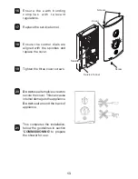
Rotate the inlet connector to 

water supply.

Secure the shower to the wall. 

$ !  
pipe.

[
    ?
1
 2   1 
2

N O T E !   -   D O   N O T

 use an 

   
shower directly from the back. 
-
      

Upper and lower case inserts are 

NOTE! - 

Trim the inserts if 

   
electrical or water supplies 

9

6

8

5

7

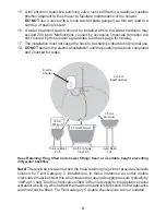
Case 
Insert

Case 
Insert

Inlet 
Connector

Summary of Contents for Mira Sport Thermostatic 9.0

Page 1: ...1 These instructions must be left with the user Installation Guide Mira Sport Thermostatic 9 0 9 8 kW ...

Page 2: ...ve separate controls for power disposal policy Mira Sport Thermostatic models covered by this guide Guarantee 1 2 Patents and Design Registration Design Registration 334567 5 3335 334567 5 3336 Patents 5 A4 BB 5 A5 AB3 Ireland 82835 Patent Application Ireland 2006 0462 Product Model Number Colour Sport Thermostatic 9 0 J03I White Chrome Sport Thermostatic 9 8 J03J White Chrome ...

Page 3: ...Installation of this shower must be carried out in accordance with these 2 electricity must be isolated at the consumer unit and the appropriate circuit is removed 3 DO NOT 1 2 4 DO NOT P P 5 DO NOT switch the shower on if there is a possibility that the water in the shower is frozen 6 DO NOT Isolate the electrical supply to the shower immediately 7 DO NOT 8 The water supplies to this product must...

Page 4: ...Tick the appropriate boxes to familiarise yourself with the part names and to 1 x Mira Sport Thermostatic 1 x Compression Nut 4 1 x Installation Guide 1 x User Guide 1 x Guarantee Brochure 1 x Installation Template 2 x Case Inserts ...

Page 5: ...5 WIRING DIAGRAM INLET CONNECTOR TERMINAL BLOCK HEATER TANK MICRO SWITCH L MICRO SWITCH R SOLENOID LED LED HOUSING PUSH BUTTON SWITCH R Z R Z U R R Z R Z R U R Z U Z R Z R Z R Z ...

Page 6: ...ure 53 13 5 2 Maximum Inlet Temperature 30 C Minimum Inlet Temperature 2 C Inlet Connection 4 5j 46 533 3 1 2 BSP Male Electrical Thermostatic Variant 9 0 9 8 Z 5 3 _ 8 3 kW 9 0 kW Z 5A3 _ 9 0 kW 9 8 kW R R A3 A6 Maximum Supply Cable Size 16 mm R R R 3 Recommended Isolator Switch A6 R IP X4 Suitable for installation in Zone 1 30 C 2 C Dimensions 358 mm Width 215 mm 90 mm ...

Page 7: ...wer WARNING TO REDUCE THE RISK OF FIRE ELECTRIC SHOCK OR INJURY Plumbing 1 2 3 1 533 2 4 56 3 6 1 2 5 a pressure relief valve It must be positioned over a water catchment area with 6 7 DO NOT 8 DO NOT 9 10 use the showerhead must not spray directly on to the shower unit 11 DO NOT 12 13 wall structure 14 DO NOT use any other ...

Page 8: ...t FC5 FC3 Bath or Shower Tray FC3 Shower 25 mm Minimum 25 mm Minimum 15 DO NOT 1 2 build up of static pressure 16 exceed 200 ppm Malfunctions caused by excessive limescale formation are 1 2 17 18 DO NOT and checked for leaks Note 43 13 4 2 6 ...

Page 9: ... must comply with BS 7671 commonly referred to as R 2 2 3 The shower must 4 must be provided from the consumer unit to the shower 5 DO NOT via this product 6 This shower must be provided with means for local disconnection that is must P 7 3 R 1R 2 8 DO NOT apply excessive force to the terminal block 9 10 DO NOT and checked for leaks ...

Page 10: ... that hold the cover on and remove the cover Remove the service tunnel U of the three Note and electrical cable to reach the connection points Remove the installation template and drill three holes to suit the Caution or pipes in the wall 1 3 4 2 Cover Screws Screw Service Tunnel ...

Page 11: ...er supply Secure the shower to the wall pipe 1 2 1 2 NOTE DO NOT use an shower directly from the back Upper and lower case inserts are NOTE Trim the inserts if electrical or water supplies 9 6 8 5 7 Case Insert Case Insert Inlet Connector ...

Page 12: ...e 1 2 U completion of the installation ensure connections and back case are not under any stress electrical cables Terminal Block Connector Cold Water Supply Pipe Inlet Connector terminal block Fit an earth sleeve to the earth wire Cables N 1Z 2 L 1 2 1 2 Green Yellow sleeved wire Turn on the water supply and check for leaks 10 11 12 13 14 15 ...

Page 13: ...6 7 8 9 10 THERMOSTATIC c o m p l i e s w i t h r e l e v a n t Replace the service tunnel replace the cover 16 17 18 19 20 21 Do not use alternative screws to secure the cover This can cause Do not seal around the back of appliance COMMISSIONING to prepare the shower for use ...

Page 14: ...n temperature control to the cold position Turn power control to low R illuminates remains cool LOW HIGH ECO POWER 1 3 2 4 6 5 0 15 secs TEMPERATURE 1 2 3 4 5 6 7 8 9 10 LOW HIGH ECO POWER Turn power control to Temperature will rise 7 5 10 secs COLD HOT ...

Page 15: ...15 LOW HIGH ECO POWER Temperature will rise further R Switch off the electrical supply from its tank for a few seconds Note 9 12 13 8 10 11 TEMPERATURE 1 2 3 4 5 6 7 8 9 10 5 10 secs COLD HOT 0 5 secs ...

Page 16: ...ullcord or wall mounted switch Renew the fuse or reset R installer Check case inserts are cut services electrical or 2 with location of service tunnel or cover Shower cycles from hot to cold Z Showerhead blocked Water pressure below shower operation Temperature control or Remove and descale showerhead Check hose and replace if necessary water stopcock and or fully turned on Turn the power control ...

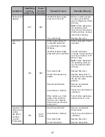
Page 17: ...water while the shower is Flush supply pipe Clean Contact local water company Supply pressure must be a minimum of 70 13 2 Note If other appliances may drop below 70 kPa 13 2 R Replace heater tank In hard water areas consider the use of a water softener Remove and descale showerhead Check hose and replace if necessary Turn off other appliances whilst shower is in use Temperature Control has little...

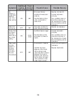
Page 18: ... not turn off Z Start Stop switch faulty Replace as necessary Shower fails to produce hot water when set on Z Possible failure of the microswitch or thermal switch Contact local water company Use a suitable device to check the continuity of the microswitch or heater tank and replace parts as necessary Water leaks from the bottom of the case and there from the showerhead Z R_ 1 has a pressure relie...

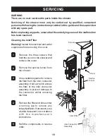
Page 19: ...onnel following the instructions provided in this guide and those provided with any spare part Before replacing any parts ensure that the underlying cause of the malfunction has been resolved Remove the three screws that hold the cover on the shower and remove the cover Remove the service tunnel from the shower Use a suitable spanner to remove R a kettle descalent in accordance instructions R orde...

Page 20: ... 01 Microswitch 15 2 1563 536 Control Belt 1746 458 9 0kW 1746 459 9 8kW 1563 719 Thermal Switch 1746 461 Connector 1746 446 416 51 Coil 416 38 Inlet Clamp 1563 540 _ 1563 538 Temp Cam Pulley 1746 462 Terminal Block A 1746 444 Switch 406 27 Inlet Filter 1746 457 Inlet Connector 1746 448 Service Tunnel ...

Page 21: ...29 area Folds up when not in use U 45 153 2 Note Must be installed onto a solid wall Premium Shower Seat White Chrome 2 1731 001 Grey Chrome 2 1731 002 shower seat for use in or outside of the shower area Folds up when not in use U 463 15 6 2 Note Must be installed onto a solid wall Logic Showerhead Holder White 2 1605 149 White Chrome 2 1605 150 when positioned for the smaller members of the fami...

Page 22: ...22 NOTES ...

Page 23: ...23 NOTES ...

Page 24: ...ce with the instructions in this manual Services Team who will offer you or your installer help and advice assistance call our Customer Services Team enable you to cover repair bills for the life of your policy 1 2 R 34755 A 4 B Helpdesk Service a service visit 1 2 or monitored Mira Showers Website www mirashowers co uk Spares and Accessories 5 45 Returns items can be returned within one month of ...

Page 25: ...1 These instructions must be left with the user LOW HIGH ECO 1 2 3 4 5 6 7 8 9 10 THERMOSTATIC TEMPERATURE POWER User Guide Mira Sport Thermostatic 9 0 9 8 kW ...

Page 26: ...ls covered by this guide Guarantee 1 2 3 any defect in materials or workmanship for a period of one year from the date of purchase Patents and Design Registration Design Registration 44567 6 34446 44567 6 34447 Patents 6 A5 BB 6 A4A 444 6 A6 AB4 6 A6 6 B 6 7 756 75B Patent Application Ireland 2006 0462 Product Model Number Colour Sport Thermostatic 9 0 J03I White Chrome Sport Thermostatic 9 8 J03J...

Page 27: ...r safety and is recommended with all electrical appliances 8 DO NOT connect the outlet of the handset or showerhead other than those should be used 9 or skin conditions can increase your WARNING Q Q R V X Y Z R V Y X R R X R Y X Y R X X Y X VV RY XV Q Q X R V X RX X XY V X V X X Y X Q Y XY X R X Y Q XV sensitivity to hot water Make sure that you set the shower to a cooler temperature 10 DO NOT ope...

Page 28: ...er control to the desired position R illuminates TEMPERATURE R and shower continues to run for a few seconds 54 3 57 to stabilise and reach the showerhead COLD HOT H Check water temperature Switch off the electrical supply may continue to drain over a few minutes 9 1 3 4 2 6 8 5 7 WARNING 3 Note Q 0 15 ...

Page 29: ...LOW HIGH ECO LOW HIGH ECO COLD HOT The Effect of Seasonal Changes LOW HIGH ECO POWER 1 2 3 4 5 6 7 8 9 10 THERMOSTATIC COLD HOT 1 2 will be controlled to within 2 C of the set temperature provided that the supply conditions 1 2 The Effect of Other Water Devices ...

Page 30: ...shower If the shower is not to be used for a water supply to the shower should be isolated If the shower or pipework is drain them of water Unscrew the hose from the showerhead and the shower outlet Inspect the hose Cleaning De scaling the Showerhead Important and free from limescale will ensure that your shower and showerhead continue to perform to your shower Inspecting the hose Important The sh...

Page 31: ...l or R water stopcock and or fully turned on Turn the power control temperature control until a cooler temperature is achieved Unable to select a shower X X Y Turn the power control temperature control until a cooler temperature is achieved X X Showerhead blocked Hose kinked or blocked 1 2 water while the shower is R Showerhead Check hose and replace USER MAINTENANCE Turn off other appliances whil...

Page 32: ...t it is installed and commissioned in accordance with the instructions in this manual V and advice simple home maintenance is required If you require further V Extended Guarantees enable you to cover repair bills for the life of your policy 1 2 R 45 66 A 5 B Helpdesk Service V and can offer help and advice spare parts accessories or a service visit We will need you to have your model name or numbe...

Reviews: