TT-1574
1/12
17
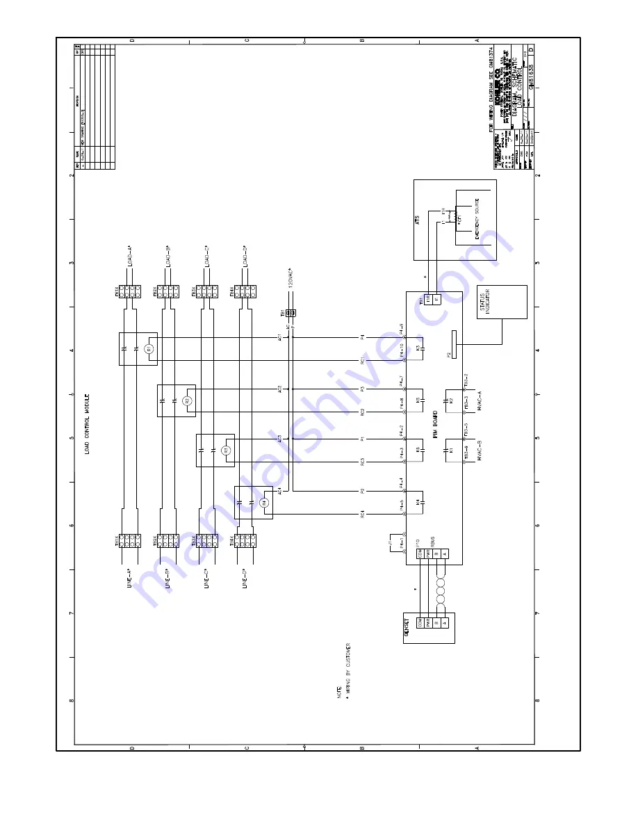
Figure 30
Schematic Diagram, LCM with Terminal Blocks for Customer Connection, GM81638 Sheet 2
Page 1: ...ctions See Figure 1 The pre wired harness requires installation of the LCM within 2 feet of the distribution panel The load control module with the optional pre wire harness is shown in Figure 2 Figur...
Page 2: ...battery WARNING Disabling the generator set Accidental starting can cause severe injury or death Before working on the generator set or equipment connected to the set disable the generator set as foll...
Page 3: ...lations use watertight conduit hubs 6 If the LCM is not equipped with a pre wired harness use the knockout provided in the bottom of the enclosure for the load leads 7 Mount the load control module LC...
Page 4: ...3 Load B 4 Load C 5 HVAC B 6 Load D Note Priority 1 Load A adds first and sheds last Figure 8 Load Priority Power Relay Load Interconnection Label Color Description L1A CB Orange Load 1 Circuit Break...
Page 5: ...uit 15 Install the LCM enclosure cover 16 Check that the generator set is OFF 17 Reconnect the generator set engine starting battery negative lead last 18 Reconnect utility power to the generator set...
Page 6: ...tions 2 3 120 VAC Power Supply Connect 120 VAC power to the terminal block labeled 120 VAC in the lower left corner of the LCM enclosure The circuit must be protected by a 15 amp fuse or circuit break...
Page 7: ...Leave one end of each cable shield disconnected at the last device RXT 1 COM PWR B A COM PWR B A Connect shields together as shown 1 Communication cable Belden 9402 or equivalent 20 AWG shielded twist...
Page 8: ...air cable 2 Engine start leads 3 and 4 See the ATS manual for cable size specifications GND A B COM PWR 3 4 TB1 NOTES D SeethegeneratorsetInstallationManualforterminal block location on generator set...
Page 9: ...k See Figure 16 1 Belden 9402 or equivalent 20 AWG shielded cable with 2 twisted pairs tp6803 PIM LCM RXT ATS Generator Set TB1 1 1 1 Figure 15 Accessory Module Connections Star Configuration three ca...
Page 10: ...ions two cable runs with one and two modules shown 1 Belden 9402 or equivalent 20 AWG shielded cable use one pair 2 12 14 AWG wire tp6803 PIM LCM RXT ATS 1 1 1 Generator Set A and B PWR COM 2 2 2 2 2...
Page 11: ...A 30 VAC A 5 minute time delay prevents HVAC loads from adding too quickly Air conditioning compressors may be damaged if they start too soon after being stopped due to the necessity of starting the c...
Page 12: ...mportant loads are re added after the generator loading has gone down enough to support them again The LCM sheds less important loads before the power quality of the generator suffers from the overloa...
Page 13: ...4 3 56 4 3 4 54 6 1 8 52 5 Hz 7 5 Hz 0 3 Figure 23 Under Frequency Shed Timing for a 60Hz Generator 4 2 3 Load Shed Acceleration The load control module uses load shed acceleration to shed loads more...
Page 14: ...ess OFF or AUTO on the RDC2 or DC2 generator set controller The TEST button does not work when the generator set is OFF or in AUTO 6 LEDs on the LCM circuit board Local LEDs on the LCM circuit board i...
Page 15: ...TT 1574 1 12 15 Figure 28 Dimension Drawing Load Control Modules ADV 8198 A...
Page 16: ...16 TT 1574 1 12 Figure 29 Schematic Diagram LCM with Pre wired Harness GM81638 Sheet 1...
Page 17: ...TT 1574 1 12 17 Figure 30 Schematic Diagram LCM with Terminal Blocks for Customer Connection GM81638 Sheet 2...
Page 18: ...18 TT 1574 1 12 Figure 31 Wiring Diagram LCM with Pre wired Harness GM81374 Sheet 1...
Page 19: ...TT 1574 1 12 19 Figure 32 Wiring Diagram LCM with Terminal Blocks for Customer Connection GM81374 Sheet 2...
Page 20: ...Assembly w Harness GM77177 1 1 Transformer Current GM83929 1 Installation Instructions TT 1574 2 Insulink X 367 1 Load Control Module with Terminal Blocks Kit GM77177 KP2 QS Qty Description Part Numb...