background image

TP-6252 2/08

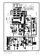
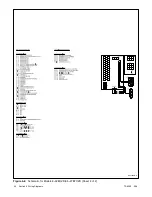
50 Section 5 Wiring Diagrams

ADV7095B-D

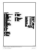
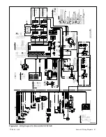
Figure 5-4

Schematic for Model 6EOD/4.5EFOD (Sheet 2 of 2)

Summary of Contents for 4.5EFOD

Page 1: ...Marine Generator Sets Models 6EOD 4 5EFOD 8 32EOZD 6 5 27EFOZD TP 6252 2 08c Operation ...

Page 2: ...aces below immediately after unpacking the products so that the numbers are readily available for future reference Record field installed kit numbers after installing the kits Generator Set Identification Numbers Record the product identification numbers from the generator set nameplate s Model Designation Specification Number Serial Number Accessory Number Accessory Description Engine Identificat...

Page 3: ...2 7 1 Line Circuit Breaker 22 2 7 2 Fuses 22 Section 3 Scheduled Maintenance 23 3 1 General Maintenance 23 3 2 Service Schedule 6EOD and 4 5EFOD Models 24 3 3 Service Schedule 8EOZD and 6 5EFOZD Models 26 3 4 Service Schedule 9 32EOZD and 7 27EFOZD Models 28 3 5 Lubrication System 30 3 5 1 Oil Specifications 30 3 5 2 Oil Check 30 3 5 3 Oil Change 31 3 6 Fuel System 32 3 6 1 Fuel Specifications 32 ...

Page 4: ... Contents 4 Section 4 Troubleshooting 43 4 1 Fault Codes 43 4 2 Controller Troubleshooting 43 Section 5 Wiring Diagrams 47 5 1 Wiring Diagram Reference 47 Appendix A Abbreviations 55 Appendix B Operating Hour Service Log 57 ...

Page 5: ...rking on the generator set or connected equipment disable the generator set as follows 1 Move the generator set master switch to the OFF position 2 Disconnect the power to the battery charger 3 Remove the battery cables negative lead first Reconnect the negative lead last when reconnecting the battery Follow these precautions to prevent starting of the generator set by an automatic transfer switch...

Page 6: ...ve fuel vapors can cause severe injury or death Vaporized fuels are highly explosive Use extreme care when handling and storing fuels Store fuels in a well ventilated area away from spark producing equipment and out of the reach of children Never add fuel to the tank while the engine is running because spilled fuel may ignite on contact with hot parts or from sparks Do not smoke or permit flames o...

Page 7: ... near the work area Some states and localities prohibit unauthorized connection to the utility electrical system Install a ship to shoretransferswitch toprevent interconnection of the generator set power and shore power Testing live electrical circuits Hazardous voltage or current can cause severe injury or death Have trained and qualified personnel take diagnostic measurements of live circuits Us...

Page 8: ...TP 6252 2 08 8 Safety Precautions and Instructions Notes ...

Page 9: ...ning of this manual Keep this manual with the equipment for future reference The generator set specification sheets provide specific generator and engine information Refer to the spec sheet for data not supplied in this manual Consult the generator set service manual engine operation manual and engine service manual for additional specifications Obtain copies of the latest spec sheets manuals diag...

Page 10: ...dquarters Europe Middle East Africa EMEA Kohler Power Systems 3 rue de Brennus 93200 Saint Denis France Phone 33 1 49 178300 Fax 33 1 49 178301 Asia Pacific Power Systems Asia Pacific Regional Office Singapore Republic of Singapore Phone 65 6264 6422 Fax 65 6264 6455 China North China Regional Office Beijing Phone 86 10 6518 7950 86 10 6518 7951 86 10 6518 7952 Fax 86 10 6518 7955 East China Regio...

Page 11: ...4 Fuse Auxiliary Winding F1 10 amp 358337 358337 358337 358337 358337 358337 358337 Fuse Relay Interface Board F2 10 amp 223316 223316 223316 223316 223316 223316 223316 Fuse Controller F3 10 amp 223316 223316 223316 223316 223316 223316 223316 Fuel Filter Element GM49315 229715 229715 GM32359 GM32359 GM32359 GM32359 Oil Filter GM40999 229678 229678 252834 252834 252834 252834 Seawater Pump Impell...

Page 12: ...d 4 5EFOD 8EOZD and 6 5EFOZD 9EOZD and 7EFOZD 10EOZD and 9EFOZD 13 15 5EOZD and 11 13EFOZD 20 24EOZD and 17 20EFOZD 28 32EOZD and 23 27EFOZD Installation Manual TP 6253 Operation Manual TP 6252 Parts Catalog TP 6268 TP 6269 TP 6270 TP 6270 TP 6271 TP 6272 TP 6273 Service Manual Engine TP 6436 TP 5876 TP 6382 TP 6293 TP 6293 TP 6293 TP 6293 Service Manual Generator TP 6255 Includes generator and en...

Page 13: ...rrosion zinc anode seawater drain all models except 13 24EOZD 11 20EFOZD models 22 Belt guard 23 V belts 24 Engine coolant drain all models except 13 24EOZD 11 20EFOZD models 25 Heat exchanger all models except 13 24EOZD 11 20EFOZD models 26 Heat exchanger 13 24EOZD 11 20EFOZD models internal to exhaust manifold 27 Seawater drain 13 24EOZD 11 20EFOZD models 28 Engine coolant drain 13 24EOZD 11 20E...

Page 14: ...enerator set to perform regular maintenance remove the sound shield doors and roof Sound Shield Roof and Door Removal 1 Open the service side door 2 Release the two quarter turn fasteners located underneath the roof See Figure 1 2 3 Lift up the roof 4 Slide the roof towards the service side of the unit for removal 5 Open the front rear and non service side doors as needed 1 1 Sound shield roof 2 Q...

Page 15: ...ndition and check for tight exhaust system connections Inspect the the exhaust system components exhaust manifold mixing elbow exhaust line hose clamps silencer and outlet flapper for cracks leaks and corrosion D Check the hoses for softness cracks leaks or dents Replace the hoses as needed D Check for corroded or broken metal parts and replace them as needed D Check for loose corroded or missing ...

Page 16: ...titute a violation of European Union Directive 2000 14 EC noise emission standard 2 5 Load Profile Whenever operating the generator set Kohler Co recommends maintaining the minimum load profile indicated in Figure 2 1 Maintaining the load profile prevents corrosion formation on internal engine components when they re exposed to the breakdown of exhaust gases Extended light loading may result in en...

Page 17: ...configuration and adjustment The controller is factory set and should not require configuration or adjustment under normal operating conditions If the generator set is reconnected to a different voltage and or frequency refer to an authorized Kohler distributor dealer for system configuration and adjustment instructions Control or Indicator Item Description LED display Runtime hours Displays total...

Page 18: ...k 2 Completely drain the water from the exhaust system at the silencer s drain plug 3 Do not attempt generator set restart 4 Contact an authorized Kohlerr distributor dealer A water filled exhaust piping and silencer may further hinder generator starting and cause seawater entry into the engine cylinders through the exhaust valves Water ingested into the engine may cause major engine damage that t...

Page 19: ...figured for a CAN gauge the controller will power down after 48 hours if the master switch is in the AUTO position If the generator has been started the controller will power down 48 hours after the generator stops 2 6 4 Fault Shutdowns The generator set shuts down automatically under the fault conditions listed in Figure 2 5 and the controller displays a fault code The generator set cannot be res...

Page 20: ... Shutdown occurs after 3 unsuccessful starting attempts The crank cycle is set for three starting attempts Check the fuel supply and battery If there is no output voltage check the line circuit breaker Also check for loose connections Contact an authorized distributor dealer for service OF Overfrequency shutdown Shutdown occurs when the governed frequency exceeds 110 of the system s frequency setp...

Page 21: ...reaker or ATS See the safety precautions at the beginning of this manual before proceeding 3 Identify and correct the cause of the fault shutdown See the safety precautions at the beginning of this manual before proceeding Refer to Section 4 Troubleshooting 4 Start the generator set by moving the generator set master switch to RUN Test operate the generator set to verify that the cause of the shut...

Page 22: ...t may indicate a blown fuse Obtain service from an authorized distributor dealer Controller Fuse A replaceable 10 amp fuse protects the controller circuitry If the controller display is dark check the battery and battery connections and then check the controller fuse Replace the fuse if it is blown Relay Fuse A replaceable 10 amp fuse protects the engine relays If the generator set does not crank ...

Page 23: ... Wipe up saltwater on and around the generator set and remove salt deposits from metal surfaces NOTICE The engine and generator set may use both American Standard and metric hardware Use the correct size tools to prevent rounding of the bolt heads and nuts See the Safety Precautions and Instructions at the beginning of this manual before attempting to service repair or operate the generator set Ha...

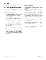
Page 24: ... Eng S M X 300 hrs Fuel injection pump Check the injection timing Eng S M X 500 hrs LUBRICATION SYSTEM Check the crankcase oil level and add oil as necessary 3 5 2 X Before operation Replace the oil in the crankcase 3 5 3 X Break in period X Replace the lube oil filter element 3 5 3 X Break in period X COOLING SYSTEM Check the coolant level and fill as necessary 3 9 2 X Before operation Check the ...

Page 25: ...rivingbelttension 3 10 2 X Replace the alternator driving belt tension 3 10 2 X Check and tighten the electrical connections X Clean the battery cables X ENGINE AND MOUNTING Check for water fuel coolant and oil leakage X After operation Inspect and or replace hoses and clamps X Retighten any loose nuts and bolts X Before operation Check the mounting bolts vibromounts and tighten if necessary X Adj...

Page 26: ...case oil level and add oil as necessary 3 5 2 X Before operation Replace the oil in the crankcase 3 5 3 X Break in period X 150 hrs Replace the lube oil filter element 3 5 3 X Break in period X 300 hrs COOLING SYSTEM Check the coolant level and fill as necessary 3 9 2 X Before operation Check the seawater outlet and clean as necessary 3 8 X Adjust the seawater pump belt tension 3 10 1 X Break in p...

Page 27: ... and in good condition w 3 11 X Before operation Adjust the alternator driving belt tension 3 10 2 X Break in period X Check and tighten the electrical connections X Clean the battery cables X ENGINE AND MOUNTING Check for water fuel coolant and oil leakage X After operation Retighten any loose nuts and bolts X Before operation Check the mounting bolts vibromounts and tighten if necessary X Adjust...

Page 28: ... hrs or 2 yrs LUBRICATION SYSTEM Check the crankcase oil level and add oil as necessary 3 5 2 X Before operation Replace the oil in the crankcase 3 5 3 X Break in period X Replace the lube oil filter element 3 5 3 X Break in period X COOLING SYSTEM Check the coolant level and fill as necessary 3 9 2 X Before operation Check the seawater outlet and clean as necessary 3 8 X Check adjust the seawater...

Page 29: ...eep the battery charged and in good condition w 3 11 X Before operation Check adjust the alternator driving belt tension 3 10 2 X Break in period X Check and tighten the electrical connections X Clean the battery cables X ENGINE AND MOUNTING Check for water fuel coolant and oil leakage X After operation Retighten any loose nuts and bolts X Before operation Check the mounting bolts vibromounts and ...

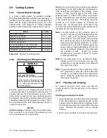
Page 30: ...0W30 20 30 40 TP 5856 1 SAE Service Grade Operating Temperature 15W40 Figure 3 1 Engine Oil Selection for Models 8 32EOZD and 6 5 27EFOZD Engine Oil Viscosity SAE Ambient Temperature Service Grade Minimum Maximum 0W20 40_C 40_F 10_C 50_F 0W30 40_C 40_F 30_C 86_F 0W40 40_C 40_F 40_C 104_F 5W30 30_C 22_F 30_C 86_F 5W40 30_C 22_F 40_C 104_F 10W30 20_C 4_F 40_C 104_F 15W40 10_C 14_F 50_C 122_F Figure ...

Page 31: ...e Open the oil drain valve on the engine f Allow time for the engine oil to drain completely Electric Oil Drain Oil Fill Pump Procedure Activate the pump until all of the oil is removed Go to step 2 g Close the oil drain valve h Replace the cap on the oil drain hose Replace the oil drain hose in its retaining clip 2 Replace the oil filter a Remove the oil filter by rotating it counterclockwise wit...

Page 32: ...ment Procedure 8 9EOZD and 6 5 7EFOZD Models 1 Close the fuel supply valve 2 Remove the collar from the fuel filter adapter while holding the filter bowl in place 3 Remove the filter bowl and fuel filter Clean the fuel filter with fresh diesel fuel and blow compressed air from the inside outward Replace a damaged fuel filter Dispose of the fuel filter in an approved manner 4 Wipe off all parts wit...

Page 33: ...edure to Bleed the Fuel System 8 9EOZD and 6 5 7EFOZD Models 1 Loosen the fuel filter screw at position 1 See Figure 3 5 2 Initiate the auto start sequence until fuel free of air bubbles flows from the vent screw at position 1 Tighten the screw 3 Loosen the fuel filter screw at position 2 4 Initiate the auto start sequence until fuel free of air bubbles flows from the vent screw at position 2 Tigh...

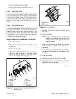
Page 34: ...4 Wipe the cover and base with a clean rag to remove any dirt Make sure that the sealing surfaces fit correctly and reattach the spring clips Figure 3 6 Air Cleaner Element Element 14 15 5 23 24EOZD and 11 5 13 20EFOZD Models A round air cleaner silences and filters the intake air Replace a damaged or dirt contaminated air silencer See Section 1 and refer to the following procedure 1 Release the t...

Page 35: ...ion Ensure that the carbon monoxide detector s is 1 in the craft 2 functional and 3 energized whenever the generator set operates For your safety Never operate the generator set without a functioning carbon monoxide detector s for your safety and the safety of others on your vessel Exhaust System Inspection Points Check for exhaust leaks and blockages Check the silencer and piping condition and ch...

Page 36: ...ten all hose clamps Use a solution of 50 ethylene glycol and 50 clean softened water to inhibit rust corrosion and prevent freezing Add additional coolant solution as necessary to the coolant recovery tank Periodically check the coolant level on closed systems by removing the pressure cap Do not rely solely on the level in the coolant recovery tank Add fresh coolant until the level is just below t...

Page 37: ... 4 Inspect the impeller for damaged cracked broken missing or flattened vanes The impeller vanes should be straight and flexible See Figure 3 10 Replace the impeller if it is damaged 1 2 3 4 5 6 7 8 9 10 1 Seawater pump 2 Coverplate 3 Gasket 4 Impeller 5 Bearing 6 Housing 7 Pulley 8 Drive shaft 9 Washer 10 Nut 11 Mechanical seal if equipped TP 6053 11 Figure 3 9 Seawater Pump Typical 8 9 10EOZD Mo...

Page 38: ...dule Siphon Break Inspection 1 Stop the generator set 2 Remove the retaining cap and remove the reed valve for inspection See Figure 3 11 3 Use a mild detergent to remove residue and oxidation from the reed valve 4 Clear blockage from the reed valve opening 5 Replace the siphon break if the reed valve is cracked or if the reed valve material has hardened or deteriorated 6 Install the reed valve in...

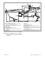
Page 39: ... same height as the heat exchanger 9 Seawater strainer 10 Seacock 11 Intake strainer 12 Engine driven seawater pump 13 Exhaust hose pitch 1 3 cm per 30 5 cm 0 5 in per ft min 14 Water lock optional 15 Silencer distance from exhaust mixer elbow 3 m 10 ft max 16 Maximum distance between silencer and exhaust outlet of 1 5 m 5 ft 17 Silencer customer supplied 18 Exhaust hose pitch 1 3 cm per 30 5 cm 0...

Page 40: ...ure 3 14 Anticorrosion Zinc Anode Replacement Models New Anode Dimensions mm in Replace When Percent of Zinc Remaining Is 8 9 10EOZD 6 5 7 9EFOZD 9 0 34 x 43 1 7 50 of length diameter 28 32EOZD 23 27EFOZD 9 0 34 x 19 0 75 50 of length diameter Figure 3 13 Anticorrosion Zinc Anode Plug Measurements TP 5586 3 1 2 1 Diameter 9 mm 0 34 in 2 Length 43mm 1 7in for 8 9 10EOZD 6 5 7 9EFOZD modelsor 19 mm ...

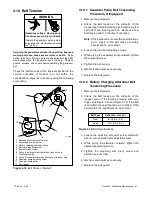
Page 41: ...awater Pump Belt Tensioning Procedure If Equipped 1 Remove the belt guard 2 Check the belt tension at the midpoint of the longest span of the belt using a belt tensioning tool set to 55 ft lbs See Figure 3 15 Recheck a new belt tension after 10 minutes of operation Note If the belt tension is not within specifications go to step 3 If the belt tension is within specifications go to step 7 3 Loosen ...

Page 42: ...7 to the low seawater pressure LWP switch 6 With a suitable container at the exhaust outlet run the generator set until coolant discharges at the exhaust outlet or until the coolant mixture is depleted Do not allow coolant mixture to flow into waterways 7 Reconnect the lead 87 to the low seawater pressure LWP switch 8 Stop the generator set 9 Connect a hose to the seacock Leave the seacock closed ...

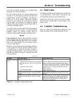
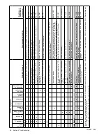
Page 43: ... Advanced Digital Control displays fault codes to aid in troubleshooting Fault codes descriptions and recommended actions are listed in Figure 2 5 Identify and correct the cause of the fault condition Then reset the controller after a fault shutdown See Section 2 6 5 4 2 Controller Troubleshooting Figure 4 1 contains troubleshooting diagnostic and repair information for the Advanced Digital Contro...

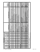
Page 44: ... circuit breaker Section 2 x Controller master or start stop switch inoperative Replace the controller master switch x Controller fault Troubleshoot the controller Gen S M x Remote stop command received from a remote switch or ATS Check the remote switch position Cooling System x x Air openings clogged Clean the air openings x Impeller inoperative Replace the impeller Section 3 x x Seawater strain...

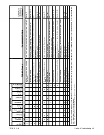
Page 45: ...he starter or starter solenoid Eng S M Engine x x x x Air cleaner backfire flame arrestor clogged Clean or replace the filter element Section 2 x x x x x Compression weak Check the compression Eng S M x x x x x Engine overload Reduce the electrical load See the generator set installation manual for wattage specifications I M x Exhaust system leak Inspect the exhaust system Replace the inoperative ...

Page 46: ...the breaker and check for AC voltage at the generator side of the circuit breaker x Overcrank shutdown Close the seacock and completely drain the water from the exhaust system at the silencer s drain plug Do not attempt generator set restart Contact an authorized distributor dealer Section 2 6 2 x Transfer switch test switch in the OFF position Move the transfer switch test switch to the AUTO posi...

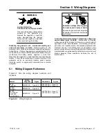
Page 47: ... computer 5 1 Wiring Diagram Reference Figure 5 1 lists the wiring diagram numbers and locations Hazardous voltage Can cause severe injury or death Operate the generator set only when all guards and electrical enclosures are in place Moving parts WARNING Grounding electrical equipment Hazardous voltage can cause severe injury or death Electrocution is possible whenever electricity is present Ensur...

Page 48: ...TP 6252 2 08 48 Section 5 Wiring Diagrams GM42202 E Figure 5 2 Wiring Diagram for Model 6EOD 4 5EFOD ...

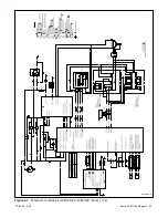
Page 49: ...TP 6252 2 08 49 Section 5 Wiring Diagrams ADV7095A D Figure 5 3 Schematic for Model 6EOD 4 5EFOD Sheet 1 of 2 ...

Page 50: ...TP 6252 2 08 50 Section 5 Wiring Diagrams ADV7095B D Figure 5 4 Schematic for Model 6EOD 4 5EFOD Sheet 2 of 2 ...

Page 51: ...TP 6252 2 08 51 Section 5 Wiring Diagrams GM50490 B Figure 5 5 Wiring Diagram for Model 9EOZD 7EFOZD ...

Page 52: ...TP 6252 2 08 52 Section 5 Wiring Diagrams GM50488 A Figure 5 6 Wiring Diagram for Models 8 10 32EOZD 6 5 8 5 27EFOZD ...

Page 53: ...TP 6252 2 08 53 Section 5 Wiring Diagrams ADV7283A A Figure 5 7 Schematic for Models 8 32EOZD 6 5 27EFOZD Sheet 1 of 2 ...

Page 54: ...TP 6252 2 08 54 Section 5 Wiring Diagrams ADV7283B A Figure 5 8 Schematic for Models 8 32EOZD 6 5 27EFOZD Sheet 2 of 2 ...

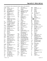
Page 55: ...oled cyl cylinder D A digital to analog DAC digital to analog converter dB decibel dBA decibel A weighted DC direct current DCR direct current resistance deg degree dept department dia diameter DI EO dual inlet end outlet DIN Deutsches Institut fur Normung e V also Deutsche Industrie Normenausschuss DIP dual inline package DPDT double pole double throw DPST double pole single throw DS disconnect s...

Page 56: ...al OS oversize overspeed OSHA Occupational Safety and Health Administration OV overvoltage oz ounce p pp page pages PC personal computer PCB printed circuit board pF picofarad PF power factor ph phase PHC Phillips head crimptite screw PHH Phillips hex head screw PHM pan head machine screw PLC programmable logic control PMG permanent magnet generator pot potentiometer potential ppm parts per millio...

Page 57: ...Log Use the log below to keep a cumulative record of operating hours on your generator set and the dates required services were performed Enter hours to the nearest quarter hour OPERATING HOURS SERVICE RECORD DATE RUN HOURS RUN TOTAL HOURS SERVICE DATE SERVICE ...

Page 58: ...TP 6252 2 08 58 ...

Page 59: ...TP 6252 2 08 59 ...

Page 60: ...ER CO Kohler Wisconsin 53044 Phone 920 565 3381 Fax 920 459 1646 For the nearest sales service outlet in the US and Canada phone 1 800 544 2444 KohlerPower com Kohler Power Systems Asia Pacific Headquarters 7 Jurong Pier Road Singapore 619159 Phone 65 6264 6422 Fax 65 6264 6455 ...

Reviews: