MDC-7000/7900 Series
Chapter 4 Setup after installation
0092669002-07
4-1
Chapter 4 Setup after installation
Some setup procedures are required after system installation. Before performing the setup procedures,
please check the following items for normal operation:
(1) The onboard power supply powering the radar system has the specified voltage.
(2) No one is in the area around the Antenna unit on the mast. The indic
ation “Under the radar
coordination, do not touch the Operation unit
.” is marked on the Display unit.
Note: Press MENU key to display
“Menu” before the menu operation.
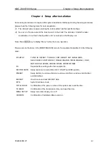
Please execute the items in the [MAINTENANCE] menu to the equipment adjustment in the following
order.
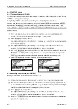
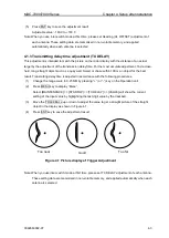
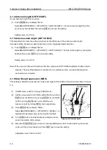
STARTUP
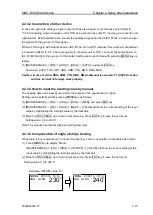
TUNE, HL OFFSET, TX DELAY, ANT HEIGHT, ANT CABLE, MBS,
SEA CURVE, FUNCTION KEY, RANGE ENABLE, TIMES ENABLE, LOGO,
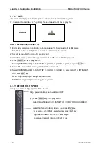
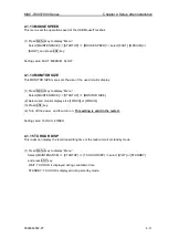
MOTOR HIGH SPEED, MOUSE SPEED, MONITOR SIZE
I/O
Serial interface setting with other equipments.
SECTOR MUTE
Setup sector mute mode ON or OFF, START and END position.
PRESET
Setup RAIN min and max, SEA min and max, GAIN min and max, GAIN offset,
and SEA offset.
BACKUP
How to save and load BACKUP data.
BITE
System hardware check.
TOTAL HOUR
Confirmation of the power on time of this system and, reset the time.
TX HOUR
Confirmation of the transmission time, and reset the time.
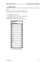
MENU SETUP
Setup menu item display on or off.
VERSION
Confirmation of installed software version.
Summary of Contents for MDC-7006
Page 1: ......
Page 2: ......
Page 44: ...Chapter 3 installation method MDC 7000 7900 Series 3 24 0092669002 07 Unit mm inch MRM 108 ...
Page 96: ... This page intentionally left blank ...
Page 134: ... This page intentionally left blank ...
Page 155: ...0092669002 07 A 1 INTER CONNECTION DIAGRAM RB807 ...
Page 156: ...A 2 0092669002 07 INTER CONNECTION DIAGRAM RB808 ...
Page 157: ...0092669002 07 A 3 INTER CONNECTION DIAGRAM RB809 ...
Page 158: ...A 4 0092669002 07 INTER CONNECTION DIAGRAM MRD 108 MRO 108 ...
Page 159: ...0092669002 07 A 5 INTER CONNECTION DIAGRAM MRM 108 MRO 108 ...
Page 160: ......

