background image

5-5

5

S

a

ving F

iles

Changing Processing Settings

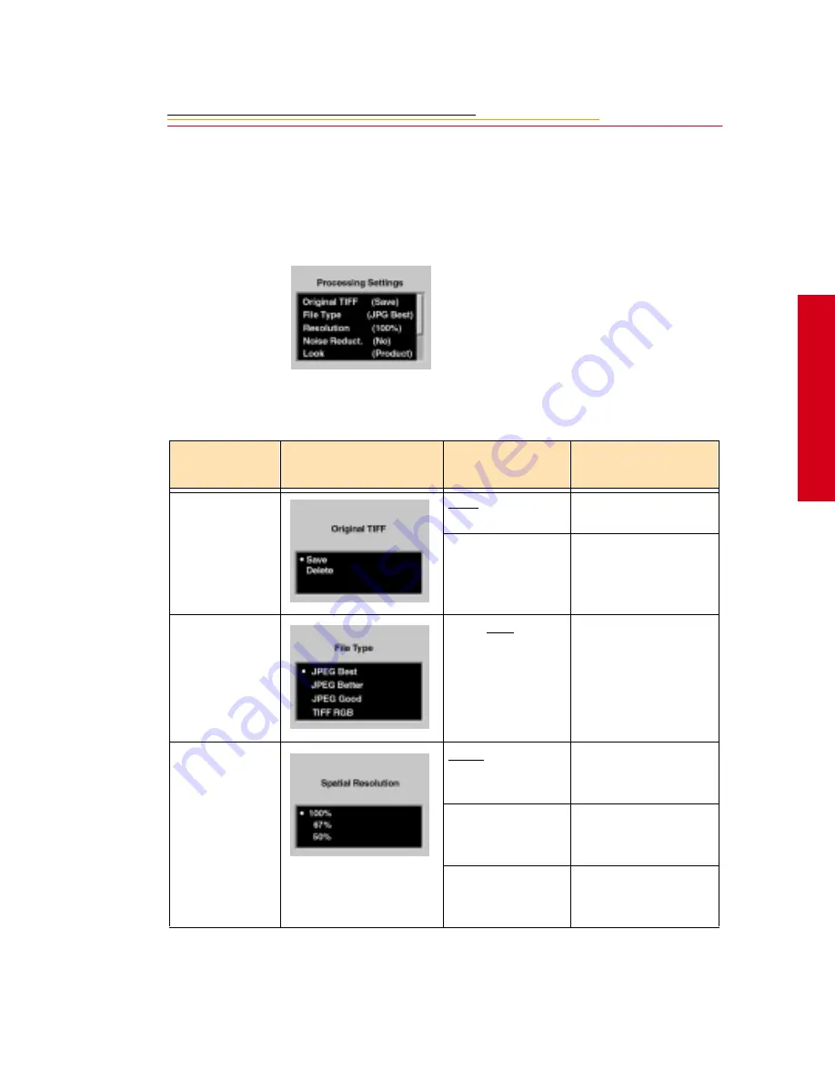
There are several processing settings that you can change. The settings are applied to 
images as they are processed.

1

Select Change Settings from the 
Processing menu. 

The Processing Settings menu 
appears with the current values 
shown in parentheses.

2

Select the desired setting.

The following screens appear, 
depending on your choice:

Processing 

Settings

Screen

Defaults 

Underlined

Result

Original TIFF

Save

Saves the TIFF image 
(default).

Delete

Deletes the TIFF 
image after the 
processed JPEG file 
has been saved.

File Type

JPEG Best, Better, 
Good, TIFF RGB

Files are processed to 
the selected JPEG 
quality.

Resolution

100%

Maintains the size and 
spatial resolution of 
the original image.

67%

The size and spatial 
resolution are reduced 
to two-thirds.

50%

The size and spatial 
resolution are reduced 
to one-half.

Summary of Contents for DCS 500 Series

Page 1: ...User sGuide forDCS500SeriesDigitalCameras DCS500SeriesDigitalCameras ...

Page 2: ...anon Inc 2000 All rights reserved Kodak and Kodak Professional are trademarks of Eastman Kodak Company CANON and EOS are registered trademarks of Canon Inc Adobe Photoshop and Acrobat are trademarks of Adobe Systems Inc PN 6b5236 ...

Page 3: ...r Coverage If this equipment does not function properly during the warranty period due to defects in material or workmanship Kodak will at its option either repair or replace the equipment without charge subject to the conditions and limitations stated herein Such repair service will include all labor as well as any necessary adjustments and or replacement parts If replacement parts are used in ma...

Page 4: ...ent with the repacking instructions This warranty does not cover the following circumstances beyond Kodak s control service or parts to correct problems resulting from the use of attachments accessories or alterations not marketed by Kodak unauthorized modifications or service misuse abuse failure to follow Kodak s operating maintenance or repacking instructions failure to use Kodak supplied items...

Page 5: ...ative will instruct you to return the unit to the nearest service center for repair and will issue a return authorization number When returning a KODAK PROFESSIONAL DCS 500 Series Camera for repair the unit should be packed in its original packing materials according to the repacking instructions located on the shipping container The problem report form located at the back of this manual should al...

Page 6: ...ofessional dealer for help with camera operation and connection to your computer Many dealers can also provide training for your graphics application software integration consulting and supporting equipment Authorized dealers can also provide help in purchasing a service maintenance agreement 4 Telephone Support Currently telephone support is provided without charge during your warranty period onl...

Page 7: ... number is provided Calls to report bugs or anomalies will have any charges cancelled Calls to arrange for service will have the charges cancelled or applied as a credit against the repair estimate or invoice Service maintenance agreements which cover the repair and support of the DCS 500 Series camera and software are available Please contact the regional Service Marketing group at North America ...

Page 8: ...ards and Precautions 1 4 Electromagnetic Emissions 1 7 VCCI Statement 1 7 About Your Camera 2 1 Features 2 1 Nomenclature 2 3 Camera Front 2 3 Camera Back 2 4 Camera Top 2 5 Camera Bottom 2 5 Camera Sides 2 6 Open Battery PC Card Door 2 7 Top LCD Panel 2 8 Back LCD Panel 2 9 Image Display 2 9 Navigation Techniques 2 11 Status Bar 2 13 Viewfinder 2 14 ...

Page 9: ...g the LCD Panels 2 21 Camera Straps 2 22 Attaching the Neck Strap 2 22 Attaching the Hand Strap 2 22 Attaching the Hand Strap and Neck Strap 2 24 Powering Your Camera 3 1 Turning the Camera On and Off 3 1 Batteries 3 2 Inserting Removing Batteries 3 3 Checking Battery Status 3 5 Battery Charger 3 6 To Charge Batteries 3 7 Conditioning 3 9 Battery Conservation 3 10 PowerSave Mode 3 10 Six Second Ti...

Page 10: ... with Two PC Cards 5 1 Processing Images 5 2 Changing Processing Settings 5 5 Working with TIFF Custom Files on your Computer 5 7 IPTC Data Management 5 8 Loading IPTC Data from a PC Card 5 9 Configuring Your Camera 6 1 Date and Time 6 1 Dioptric Adjustment of the Viewfinder 6 2 Custom Functions 6 3 Selecting and Setting Custom Functions 6 3 Resetting Individual Custom Functions 6 5 Resetting All ...

Page 11: ...ctions 6 26 Quick Start 7 1 Before You Start 7 1 The AC Adapter 7 5 Optional Settings Before You Start 7 6 Setting White Balance 7 7 Selecting a PC Card or Folder 7 7 Capturing Images 7 9 Reviewing Images on Your Camera 7 10 Setting Display Contrast 7 11 Setting Display Options 7 12 Tagging Images 7 13 Deleting Images 7 14 Deleting a Single Image 7 14 Deleting More Than One Image 7 15 Associating ...

Page 12: ...g 8 33 AE Lock 8 34 Exposure Compensation 8 37 Setting Exposure Compensation 8 37 Using the Exposure Compensation Button 8 39 Auto Exposure Bracketing AEB 8 40 Using Flash 8 44 General Information on Canon EOS Dedicated Speedlites 8 44 Using Canon EX series Speedlites 8 45 Using Canon EZ EG or E Series Speedlites 8 50 Using Exposure Modes with E TTL A TTL and TTL flash 8 52 Flash Exposure Compensa...

Page 13: ...i aliasing Filter Effect on Focus 9 12 Sharpening 9 12 Capturing Images 10 1 Shutter Button Operation and Autofocus 10 2 Pressing the Shutter Button Halfway 10 2 Pressing the Shutter Button Completely 10 3 Changing the Drive Mode 10 3 Single Exposure 10 3 Continuous Exposure 10 3 Maximum Continuous Shooting Speed in Different AF Modes 10 4 Using the Self timer 10 5 Using the Eyepiece Shutter 10 6 ...

Page 14: ...n One Image 11 12 Recovering Deleted Images 11 13 Connecting to Your Computer 12 1 Advantages to using an IEEE 1394 Connection 12 1 Advantages to using a Card Reader 12 1 Connecting Your Camera to the Computer 12 2 Quitting Disconnecting from the Computer 12 4 Using the Card Reader 12 4 Transmitting Data 13 1 Connecting a Device to the Serial Port 13 1 Accessing Serial Port Options 13 2 Setting th...

Page 15: ...Imager 14 4 Determining if the Imager is Dirty 14 4 Cleaning the Imager 14 7 Reassembling the Camera 14 7 Storing 14 8 Top and Back LCD panels 14 8 Installing Camera Firmware on Your Computer 14 9 Updating Camera Firmware 14 9 Downloading From the PC Card 14 9 Appendix A Specifications A 1 Appendix B Troubleshooting B 1 Appendix C Problem Report C 1 ...

Page 16: ...uality Before you start using the camera follow the instructions listed below Read the Warranty statement Read the Software License Agreement associated with the software CD Verify that your camera package contains everything mentioned in the list of Package Contents Verify that your Macintosh or PC meets the System Requirements Read the Warnings section Review the Important Safeguards and Precaut...

Page 17: ...ards if tethering camera without on board IEEE 1394 port 15 inch or larger color display 24 bit recommended ADOBE PHOTOSHOP software version 4 0 4 01 5 0 or 5 5 or software that supports PHOTOSHOP Acquire Plug ins WINDOWS Personal computer with a 100 MHz Pentium processor with on board IEEE 1394 port and or PCI bus slots available and or PC Card reader IEEE 1394 adapter cards if tethering camera w...

Page 18: ...e PC Card You may lose data if you remove a card at this time Refer to PC Cards on page 4 1 You should operate your camera only from the type of power source indicated on the name plate of the AC adapter A line voltage outside of this range can destroy the AC adapter and or the camera Use only the supplied AC adapter Do not plug other adapters into the camera The AC adapter is for indoor use only ...

Page 19: ...eat the imager and the anti aliasing filter as you would your best lens Do not drop your camera Do not place your camera on an unstable cart stand bracket or table It can fall causing serious injury to persons and serious damage to your camera Dust If you operate the camera in environments with excessive dust levels dust may accumulate on the camera Water and Moisture Do not use the camera in heav...

Page 20: ...at you are not likely to walk on them or pinch them with items placed on or against them Pay particular attention to cords at plugs receptacles and the point where they leave your camera Grounding The AC adapter is equipped with a three wire grounding type plug with a third grounding pin The three wire plug will fit into a grounding type power outlet This is a safety feature If you are unable to i...

Page 21: ... yourself Opening or removing covers may expose you to dangerous voltage or other hazards and void the warranty Damage Requiring Service Unplug your camera from the wall outlet and computer and refer all servicing to the manufacturer under the following conditions If liquid has been spilled or if objects have fallen into your camera If your camera has been exposed to heavy rain or water While it i...

Page 22: ...t the interference by one or more of the following measures Reorient or relocate the receiving antenna Increase the separation between your camera and receiver Connect your camera into an outlet on a circuit different from that to which the receiver is connected Consult the dealer or an experienced radio TV technician for help This equipment conforms with the requirements of European Standard EN55...

Page 23: ... vary depending on your camera Image size DCS 520 2 million pixels 1728 x 1152 2 3 aspect ratio DCS 560 6 million pixels 2008 x 3040 2 3 aspect ratio Finished file size DCS 520 6 MB DCS 560 18 MB ISO DCS 520 200 1600 DCS 560 80 200 Continuous frame rate DCS 520 3 5 frames sec If memory is full burst depth of 12 is reached the rate is temporarily reduced to 5 frame sec DCS 560 1 frame sec If memory...

Page 24: ... data IPTC data in image header Full image viewfinder Anti aliasing filter to minimize color aliasing or IR filter to improve image quality Controls for vertical shooting Name plate that you can personalize Remote port connector for Canon accessories IEEE 1394 connection to computer high speed serial bus E TTL flash control Your camera utilizes Canon EF lenses designed for 35 mm film frames Since ...

Page 25: ... with the regular kit Self Timer Indicator Palm door to access Custom Functions Depth of Field Preview Button Vertical Control Switch White Balance Sensor Canon Remote Port Lens Attachment Mark red Lens Mount Anti aliasing or IR filter Shutter Button Lens Lock Pin Strap Attachment Lens Release Button PC Terminal Cover for flash sync external Battery PC Card door to access battery and PC Card Verti...

Page 26: ... Lock button Quick Control Dial switch Palm Door Quick Control dial Microphone Main switch Vertical AE Lock button Shooting Mode Selector AF Mode Selector Metering Mode Selector Flash Exposure Compensation button Viewfinder Eyepiece Image Display RECORD TAG button DISP MENU button SELECT button W BAL button Back LCD panel ...

Page 27: ...sory Shoe Shooting Mode Selector AF Mode Selector Metering Mode Selector Flash Exposure Compensation button Tripod Socket Strap Attachment Data Serial Number Label LCD Panel Illumination button Exposure Compensation button Shutter button Main dial Top LCD panel ...

Page 28: ...2 6 Camera Sides Strap Attachment Palm Door AC Adapter Connection IEEE 1394 Connection Viewfinder Dioptric Adjustment dial PC Terminal Cover for flash sync external Battery PC Card Door ...

Page 29: ...2 7 2 Your Camera Open Battery PC Card Door Battery in slot Serial Port Card Busy light PC Card in slot Eject button ...

Page 30: ...tion AEB Bulb Exposure Time Self Timer Countdown Shutter Speed ISO Battery Check bc Bulb bulb Depth of field AE dEP Custom Function Control Focusing Points ISO Indicator AF Mode Indicator One shot AF AI Servo AF Drive Mode Indicator Single Exposure Continuous Exposure Self Timer 10 second timer 2 second timer Exposure Level Indicator Bulb Exposure Time AEB Value Amount Indicator Flash Exposure Com...

Page 31: ... on the Image Display the last screen used appears without the Menu bar If you then press the DISP MENU button the Menu bar appears Shortcut press and hold the DISP MENU button to turn on the Image Display and display the Menu bar When the Menu bar is displayed the remainder of the screen is grayed out Remaining Frames Frame Number White Balance Auto Daylight Tungsten Fluorescent Flash Battery Sta...

Page 32: ... Folder dropdown menu One PC Card Two PC Cards Menu icon Displays a dropdown menu with choices for the Main Properties and Custom Settings menus Display icon Displays a dropdown menu with choices for Single Four and Nine Image Review mode Contrast icon Displays the Display Contrast screen where you can adjust contrast ...

Page 33: ...y To display the Menu bar and select a Menu bar icon Press and hold the DISP MENU button and rotate the Quick Control dial until the desired icon is highlighted To display a Dropdown menu Highlight the Folder Menu or Display icon and continue pressing the DISP MENU button until the dropdown menu appears ...

Page 34: ...Continue to press the DISP MENU button and rotate the Quick Control dial until the desired menu choice is highlighted To chose an item from a menu screen Press and hold the SELECT button and rotate the Quick Control dial to highlight your choice ...

Page 35: ...de Information about the currently selected image appears on the Status bar The currently active PC Card if there are two cards in the camera The currently active folder Sound icon if one or more sound files are associated with the selected image Tag icon if the selected image has been tagged Two PC Cards One PC Card ...

Page 36: ...xposure Level Display Fine Spot Metering Area The viewfinder represents the actual live area of the CCD sensor This illustration represents the viewfinder for the DCS 520 camera The metering area is larger for the DCS 560 camera Exposure Step Indicator 1 stop 1 3 stop Correct Exposure Indicator Overexposure Indicator 3 stops or more Exposure Level Indicator Underexposure Indicator 3 stops or more ...

Page 37: ...isabled for a short period of time after each exposure If you change a camera setting with the dial immediately after capturing an image check that the camera responded appropriately Using the Quick Control Dial For Digital Functions The Quick Control dial can access functions available through the Image Display or the Back LCD panel when you use it in conjunction with one or more of the following...

Page 38: ... 26 and Bulb exposure page 8 28 Flash exposure compensation page 8 54 Custom functions F5 and F11 page 6 3 Various combinations of these two functions modify the way you set shutter speed and aperture value 1 Set the Quick Control Dial switch to On to access the functions listed above 2 Refer to the appropriate section of the manual for information on the desired functions When finished set the sw...

Page 39: ... and release the button to turn the Image Display on or off Press and hold the button and use the Quick Control dial to scroll through the menu bar icons SELECT Button Press and hold the button and use the Quick Control dial to scroll through images or menu options Release the button to select the desired image or menu option Hold down the DISP MENU button and the SELECT button at the same time to...

Page 40: ...ts on the lens and camera body then rotate the lens clockwise until it locks in place with a click 3 Set the lens Focus Mode switch to AF Autofocus is not possible when the switch is set to M During autofocusing do not touch the rotating part of the lens Some Canon lenses are manual focus only AF M 8 0 m m 1 1 4 AF M 22 22 50mm AF M ...

Page 41: ...place it face down on a stable surface to prevent damage to the electronic contacts 4 Remove the front lens cap To remove the lens press the Lens Release button and turn the lens counterclockwise ULTRASONIC CANON N LE S EF 50mm 1 1 4 C A N O N N L E S M DA E I N J A AP N M A F N ...

Page 42: ...he DCS 560 imager is 6 million pixels and operates at 80 200 ISO Anti aliasing filter Your camera contains an anti aliasing filter which helps to prevent aliasing at certain focal distances IR Filter The DCS 520 camera base camera kit uses an IR filter in place of an anti aliasing filter Refer to page 9 12 for information on the effect of the anti aliasing filter on focus ...

Page 43: ...nds To turn off the illumination before six seconds elapse press the Panel Illumination button again The LCD panel illumination goes out automatically approximately two seconds after you capture an image You can keep the Top and Back LCD panels illuminated longer than six seconds by pressing any operation button again while the illumination timer is activated The LCD panels cannot be illuminated d...

Page 44: ...es 1 Thread the strap through both loops in the hand strap pad 2 Place the three holed buckle on the strap and thread through the camera s top strap fixture 3 Thread the other end of the strap through the camera s bottom strap fixture CAUTION If you are planning to use both the neck strap and the hand strap at the same time follow the instructions for attaching both the hand strap and neck strap d...

Page 45: ...the strap back through the loops on the hand strap pad 6 Place the two holed buckle on the top strap 7 Tuck the top strap through the bottom loop in the hand strap pad 8 Thread the bottom strap through the two holed buckle as shown 9 Tuck the bottom strap through the top loop in the hand strap pad ...

Page 46: ...2 24 Attaching the Hand Strap and Neck Strap 1 Attach the Hand Strap page 2 22 2 Thread the neck strap through the three holed buckle as shown ...

Page 47: ...serve battery power by using the AC adapter while working indoors or when your camera is connected to a computer Use a battery charger and an international power cord set with your camera The power cords allow you to use the AC adapter and the battery charger in Australia Britain Germany Japan and the United States Turning the Camera On and Off Set the Main switch to A to turn the camera on Set it...

Page 48: ...a NiMH battery NiCd battery DCS 520 1000 300 DCS 560 300 100 WARNING All batteries can explode or cause burns if disassembled shorted exposed to high temperatures or disposed of in fire Be sure to observe all precautions indicated on the battery package Always keep batteries out of the reach of children and follow the instructions on the battery label for recycling when you are finished with them ...

Page 49: ... the PC Card icon on the Back LCD panel 2 Turn off the camera 3 Place your index finger on the Battery PC Card door switch and press downward while opening the door with your thumb and finger IMPORTANT If the icon is blinking wait until it stops before continuing You can lose data if you remove the battery while the card is busy ...

Page 50: ... You can insert or remove a battery while the camera is connected to the AC adapter IMPORTANT Be sure that the red warning light is off before continuing IMPORTANT The battery can be inserted incorrectly but it will not fully seat into the camera Do not force the battery into the camera Insert the end with the slots pointed down and press lightly to seat the battery contacts ...

Page 51: ...ery status at the following times When loading a new battery After lengthy storage If the shutter will not release In cold weather Before an important shooting assignment 1 Insert a battery in the camera page 3 3 2 Turn on the camera 3 Check the Battery Status icon on the Back LCD panel The icon indicates whether the battery needs changing The Battery Check function on the Top LCD panel does not f...

Page 52: ...emperature ranges Storage temperature range 25 C to 70 C 77 F to 158 F Charging temperature range 0 C to 45 C 32 F to 113 F The battery charger has two slots Lights near the slots illuminate to indicate the status of the batteries as follows Although you can use a battery when the light turns green you will have optimal results if you leave the battery in the charger for 2 hours after the light tu...

Page 53: ...Remove the battery from the camera page 3 3 2 Plug the cable from the AC adapter for charger into the battery charger jack 3 Select the international power cord that is appropriate for your area 4 Plug the power cord into a wall outlet ...

Page 54: ...ger slots On average the charger will completely charge a battery in approximately one hour If two batteries are inserted they are charged sequentially 6 Once the green light turns on wait two hours then remove the battery or batteries from the charger If you don t wait two hours batteries will only be charged to 80 of capacity 7 Insert a charged battery into the camera 8 Close the camera door The...

Page 55: ...oo often or they will wear out prematurely 1 Insert one or two batteries in the battery charger slots 2 Press the Condition buttons associated with the batteries that you wish to condition The battery will first be conditioned then charged The whole process can take up to 5 1 2 hours 3 Remove the batteries from the battery charger when the lights turn green You can condition a battery in one slot ...

Page 56: ...om PowerSave Mode Six Second Timeout When you release the Shutter button after pressing it halfway the Top LCD panel Back LCD panel and viewfinder displays remain illuminated for six seconds Situations Using Extra Battery Power Use of a telephoto or wide angle fisheye lens and constant auto focusing Frequent use of the Image LCD panel Cold temperatures Turning the camera on and off frequently Ligh...

Page 57: ...n your battery considerably To minimize the drain the Image Display turns off if you have not performed any camera activities for 60 seconds The Image Display does not turn off if the AC adapter is connected To Restore the Image Display Press the DISP MENU button ...

Page 58: ...es not have an On Off switch To turn off the AC adapter unplug it CAUTION Operate the equipment only from the type of power source indicated on the AC adapter A line voltage outside of this range can destroy the AC adapter and or the camera IMPORTANT Use only the AC adapter included with your camera or available from Kodak as an accessory Do not plug other chargers or adapters into the camera Do n...

Page 59: ... side of the camera 2 Plug the AC adapter into the AC Adapter connection 3 Select the universal power cord that is appropriate for your area 4 Plug the appropriate end of the power cord into the AC adapter 5 Plug the power cord into a wall outlet You can connect or disconnect the AC adapter while a battery is in the camera ...

Page 60: ...ing images PC Cards Your camera is designed to accept Type II or Type III PC Cards which are compatible with the PCMCIA ATA interface standard Most hard disk drive and flash memory cards may be used Hard disk drive cards will hold more images and are usually faster than flash memory cards but flash memory cards are more rugged PC Cards must be ATA compatible IMPORTANT Use extreme care when handlin...

Page 61: ... one card insert it in either slot With two cards the first card inserted is the active card When you capture or delete images they are saved to or deleted from the active card IMPORTANT Your camera uses 3 volt or 5 volt PC Cards When you use two cards they must both have the same voltage If you insert two cards with different voltages neither is powered A Card Voltage Mix message will appear You ...

Page 62: ...ard 1 Check the Card icon on the Back LCD panel It blinks when a card is busy 2 Place your index finger on the door latch and press downward while opening the Battery PC Card door with your thumb and finger IMPORTANT Do not remove a card while the icon or the Card Busy light are blinking You can lose data if you remove the PC Card while it is busy ...

Page 63: ... slide the PC Card all of the way into the lower slot and press firmly A label inside the door indicates the proper position for the card IMPORTANT Before continuing be sure that the red warning light is not blinking ...

Page 64: ...4 5 4 PC Cards To remove press the Eject button and pull the PC Card out 4 Close the Battery PC Card door The Card icon is displayed on the Back LCD panel when there is a card in the camera ...

Page 65: ...ossibility that there are defects on the PC Card media The Recover function only works if a PC Card has been formatted on the camera 1 Select the Menu icon then choose Main Menu from the dropdown menu Refer to Navigation Techniques on page 2 11 2 Select Card from the Main menu The Card menu appears 3 Choose Quick Format or Full Format If two cards are in the camera you are prompted to remove the i...

Page 66: ...n screen appears 6 Select Yes or No If you choose No the Main menu appears and the card is not formatted If you choose Yes the card is formatted A Progress screen appears If you wait for the progress bar to go to completion a full format occurs If you press the Cancel button a quick format occurs With a quick format the card will be usable but occasional errors may occur when you save images ...

Page 67: ... an X appears within the Folder icon Selecting the icon produces this screen With one PC Card this dropdown menu appears with a displayed next to the currently active folder With two PC Cards this dropdown menu appears with a displayed next to the currently active card and the currently active folder on that card A 0 or 1 appears in the Folder icon indicating the active PC Card The listed folders ...

Page 68: ... images JPEG files are saved to a JPEG folder and TIFF RGB files are saved to a TIFF folder These folders are created on the PC Card when you turn on processing if they don t already exist If you select the JPEG or TIFF folder to review images then you capture an image a message informs you that images cannot be saved there You can specify whether the original TIFF file is saved or deleted once th...

Page 69: ...ce The Processing confirmation screen appears 4 Select OK to begin processing or Cancel to return to the Main menu without processing Choice Images Processed OFF Turns off processing Tagged in folder All tagged images in the selected folder on the active card All in Folder All images in the selected folder on the active card Tagged Images All tagged images on the active card All on Card All images...

Page 70: ...folder If processing is enabled for tagged images or all images on the card then images are processed as you tag or capture them If you click Cancel processing is not started Processing is enabled for the selected folder and all images in the folder have been processed Similar screens appear when the same condition exists for tagged images or for all images on the card There are two PC Cards in th...

Page 71: ... you click Cancel Processing is not started The Processing menu appears The active PC Card becomes full as images are being processed This can occur regardless of whether there are one or two cards in the camera Click OK and delete some images or insert a different card You remove a PC Card while processing is enabled whether or not images are currently being processed Condition Screen Your Action...

Page 72: ...ng The following screens appear depending on your choice Processing Settings Screen Defaults Underlined Result Original TIFF Save Saves the TIFF image default Delete Deletes the TIFF image after the processed JPEG file has been saved File Type JPEG Best Better Good TIFF RGB Files are processed to the selected JPEG quality Resolution 100 Maintains the size and spatial resolution of the original ima...

Page 73: ...sed images No Noise is not reduced Look Portrait Applies a lower contrast tone scale with more detail in the highlights and shadows Product Applies a higher contrast more vibrant tone scale Sharpening Level None No sharpening is applied to the finished image High Progressively less sharpening is applied to the finished image Medium Low Exposure Yes Automatic exposure compensation is applied No Aut...

Page 74: ... image editing and acquire software applications If the DCS Host Software CD included with your camera includes the DCS Acquire Module and DCS TWAIN Data Source version 5 8 or later you will be given the option of installing the DCS File Format Module If the CD includes a version prior to 5 8 the DCS File Format Module is not included To download the DCS File Format Module visit the Kodak Web site...

Page 75: ...nual Once IPTC data has been saved to a PC Card you can load the data into your camera page 5 9 1 Select the Menu icon then choose IPTC Data from the dropdown menu Refer to Navigation Techniques on page 2 11 2 Select your choice from the IPTC Data menu None No IPTC data is written to the image headers IPTC Data File If there is an IPTC file on the camera it is displayed Choosing this option writes...

Page 76: ...d choices do not appear 2 Press and hold the SELECT button and rotate the Quick Control dial to choose the desired card You may need to scroll up to the card choices if there are numerous IPTC files 3 Repeat step 2 to choose an IPTC file The file is loaded from the PC Card to your camera Each file must have a unique name If you attempt to load a file with the same name as one on your camera a mess...

Page 77: ...and the format for time is hour minute second based on a twenty four hour clock The setting is maintained when you turn off the camera after Powersave or when you remove the battery for a few days There is a small rechargeable battery in the camera than can lose its charge if you remove the main battery for a long period of time In this case you would need to reset the date and time after replacin...

Page 78: ...and hold the SELECT button and rotate the Quick Control dial to change the highlighted field 4 Release the SELECT button to accept the change and highlight the next field To leave a field unchanged press and release the SELECT button without using the dial When the seconds field is highlighted and you press the SELECT button the seconds stop counting Look into the viewfinder and turn the Dioptric ...

Page 79: ...Some have more than two settings The default setting for each custom function is 0 for example F 9 0 All other settings are optional for example F 9 1 F 9 2 or F 9 3 Select one setting per custom function Selecting and Setting Custom Functions 1 Set the Main switch to A 2 Open the palm door and press the Custom Function CF button A custom function number is displayed in the Top LCD panel 3 Turn th...

Page 80: ... A dot below 2 indicates that an optional setting for custom function F 4 has been selected Dots for other custom functions appear to the right or left of the 2 position You can check the custom function settings at any time by pressing the CF button to activate the Top LCD panel 5 Press the Shutter button halfway to complete the setting and restore the Top LCD panel to the original display 3 2 1 ...

Page 81: ...m function to the standard default setting select the custom function and then press the CF button to change the number in the Top LCD panel to 0 2 Press the Shutter button halfway to complete the setting and restore the Top LCD panel to the original display 1 Set the Main switch to A 2 Open the palm door and press the CF button 3 Press the Clear button 3 2 1 1 2 3 0 ...

Page 82: ...Chart Type Custom Function No Affected Function Top LCD Panel Display Setting No Beeping on off F 3 Beeping when in focus 0 1 Focus F 4 AF Operation method 0 1 F 4 AF Activation 2 3 2 1 1 2 3 0 3 2 1 1 2 3 0 3 2 1 1 2 3 0 ...

Page 83: ... AE Lock button T is pressed Autofocus starts when the AE Lock button T is pressed Exposure is locked when the shutter button is pressed halfway 1 This option lets you carry out metering and autofocusing independently Autofocus starts when the Shutter button is pressed halfway Focus is locked when the AE Lock button T is pressed 2 For sports photography using focus prediction in AI Servo AF mode t...

Page 84: ...ing No Exposure F 5 Shutter speed and aperture value setting method in Manual Exposure mode 0 1 F 6 EV steps for the shutter speed aperture exposure compensation flash exposure compensation and AEB 0 1 2 3 2 1 1 2 3 0 3 2 1 1 2 3 0 3 2 1 1 2 3 0 3 2 1 1 2 3 0 3 2 1 1 2 3 0 ...

Page 85: ...hutter speed or aperture value This option is convenient for studio flash photography where the shutter speed is kept constant while the aperture is frequently varied to alter the depth of field and exposure Shutter speed aperture value exposure compensation flash exposure compensation and AEB step amounts are set in 1 3 stop increments Shutter speed and aperture value are set in 1 stop increments...

Page 86: ...6 10 Type Custom Function No Affected Function Top LCD Panel Display Setting No Focus F 7 Manual focusing with the electronic manual focusing ring 0 1 3 2 1 1 2 3 0 3 2 1 1 2 3 0 ...

Page 87: ...e Lens Focus Mode switch to M is possible This option disables the manual focusing capability of the electronic ring provided on many USM lenses eliminating the possibility of accidentally turning the ring and shifting the focus after autofocusing is complete Compatible Lenses EF50 1 0L USM EF 85 1 2L USM EF 200 1 8L USM EF 300 2 8L USM EF 400 2 8L USM EF 500 4 5L USM EF 600 4L USM EF 1200 5 6L US...

Page 88: ...ed Function Top LCD Panel Display Setting No Exposure F 8 Center weighted average metering 0 1 F 9 AEB Auto Exposure Bracketing exposure sequence 0 1 2 3 3 2 1 1 2 3 0 3 2 1 1 2 3 0 3 2 1 1 2 3 0 3 2 1 1 2 3 0 3 2 1 1 2 3 0 3 2 1 1 2 3 0 ...

Page 89: ...Lens is exchanged bulb exposure mode is set flash charge completion is detected or the Clear button is pressed 1 3 AEB operation is not canceled when the Main switch is set to the Lens is exchanged AEB mode can be selected by simultaneously holding down the AF Mode and Shooting Mode selectors and turning the Main dial 2 3 These settings change the bracketing sequence to 0 which is useful when shoo...

Page 90: ...n Top LCD Panel Display Setting No Focus F 10 Elimination of AF frame display 0 1 F 11 Focusing point selection 0 1 2 Mirror operation F 12 Mirror up operation 0 1 3 2 1 1 2 3 0 3 2 1 1 2 3 0 3 2 1 1 2 3 0 3 2 1 1 2 3 0 3 2 1 1 2 3 0 3 2 1 1 2 3 0 ...

Page 91: ... when the 6 second metering timer is activated or during continuous shooting in Al Servo AF mode After the far left or far right focusing point is selected selection cannot proceed in the same direction 0 1 This option makes it possible to match your camera s button operations to existing EOS 1 or EOS 5 A2 A2E cameras 2 This option lets you track the subject with the focusing point in real time by...

Page 92: ... Custom Function No Affected Function Top LCD Panel Display Setting No Exposure F 13 Spot metering at the AF frame 0 1 Flash F 14 Fill in flash control 0 1 3 2 1 1 2 3 0 3 2 1 1 2 3 0 3 2 1 1 2 3 0 3 2 1 1 2 3 0 ...

Page 93: ...for the center focusing point only This function links spot metering to the focusing point allowing you to spot meter the subject without changing the framing of the scene Automatic flash output reduction control active Automatic flash output reduction control prohibited This function prevents underexposure of strongly backlit subjects for example when you are shooting portraits backed by light fr...

Page 94: ... Set by Main dial Shutter speed 1 Set by Quick Control dial or 2 Set by Exposure Compensation button and Main dial 1 Shutter speed Set by Main dial Aperture value 1 Set by Quick Control dial or 2 Set by Focusing Point selector and Main dial Aperture value Set by Main dial Shutter speed 1 Set by Quick Control dial or 2 Set by Focusing Point selector and Main dial 2 Shutter speed Set by Main dial Ap...

Page 95: ...re set as shown below Function Setting Shooting mode Program AE P mode AF mode One shot AF Metering mode Evaluative metering Drive mode Single exposure Custom functions Not affected Caution When custom function F 8 is set for center weighted average metering instead of evaluative metering and the metering mode is set to partial metering or spot metering pressing the Clear button will reset all of ...

Page 96: ...6 20 Resetting All Custom Functions Reset all of the custom functions to their initial settings by pressing the Custom Function CF button before pressing the Clear button ...

Page 97: ...the length of time before the Back LCD panel turns off 1 Select the Menu icon then choose Properties from the dropdown menu page 2 11 1 With the Properties menu displayed select Display Off Time The Display Off Time screen appears This screen and the Powersave screen operate a little differently than the others 2 Press and hold the DISP MENU button A vertical arrow appears at the right of the scre...

Page 98: ...ol dial to highlight a different number 7 Release the DISP MENU button The horizontal arrow goes away and the new number is highlighted 8 Repeat steps 2 through 7 as needed The DISP MENU button toggles between the vertical arrow that changes the value of a number and the horizontal arrow that selects a different number 9 Select OK to establish the new setting or Cancel to retain the original setti...

Page 99: ... process an image Refer to Processing Images on page 5 2 This section describes the camera s Sharpening property which determines whether sharpening is applied by the DCS Host Software s At Capture setting in the Sharpen Image preference If you set the Sharpen Images preference to On or Off images are sharpened or not regardless of the camera property setting Refer to the DCS Host Software User s ...

Page 100: ...the dropdown menu Refer to Navigation Techniques on page 2 11 2 Select Resolution from the Properties menu The Image Resolution screen appears 3 Select Resolution or Units If you select Resolution the Resolution screen appears 4 Press and hold the SELECT button and rotate the Quick Control dial to change the highlighted field 5 Release the SELECT button to accept the change and highlight the next ...

Page 101: ...ult place to store images is an empty folder or folder 1 when you insert a new PC Card With the Properties menu displayed select Total Actuations The Total Actuations screen appears informing you of the number of images captured 1 With the Properties menu displayed select Use FOLDER01 This Use Folder 1 screen appears 2 Highlight Yes or No If you select Yes every time you replace your PC Card image...

Page 102: ...ctions are described earlier in this Chapter 1 With the Properties menu displayed choose Dropdown Menu Lag The Dropdown Menu Lag screen appears 2 Choose a number from 1 to 5 1 gives the longest delay and 5 gives the shortest A setting of 3 provides a 750 millisecond delay 1 With the Properties menu displayed select the desired Custom Function This appropriate Custom Function screen appears 2 Press...

Page 103: ...ide Before You Start 1 If you have not already done so charge your battery using the external battery charger that was included with your camera This is not included in the base camera kit You can insert either one or two batteries in the battery charger The lights on the battery charger will turn green when the batteries are completely charged Refer to Chapter 3 for more information on batteries ...

Page 104: ...ry PC Card door 4 Insert the battery into the battery slot When working indoors conserve your battery and power your camera using the AC adapter that is provided with your camera 5 Insert a PC Card into the lower card slot ...

Page 105: ...cus mode One Shot AF or AI Servo AF by holding down the AF Mode Selector button and turning the Main Dial Refer to Selecting the AF Mode on page 9 2 10 Select a shooting mode by holding down the Shooting Mode Selector button and turning the Main dial Refer to Selecting the Shooting Mode on page 8 11 11 Select a metering mode by holding down the Metering Mode Selector button and turning the Main di...

Page 106: ...sing the Drive button then turning the Main dial Refer to Changing the Drive Mode on page 10 3 13 Set the ISO value by holding down the AF Mode Selector and the Metering Mode Selector buttons and turning the Main dial Refer to Setting the ISO on page 8 10 14 Lightly press the Shutter Release to wake the camera ...

Page 107: ...t with the base camera kit Refer to AC Adapter on page 3 12 Connecting the AC Adapter 1 Plug the AC adapter into the camera the unit plugs into the round connector on the side of the camera 2 Select the universal power cord that is appropriate for your area 3 Plug the appropriate end of the power cord into the AC adapter 4 Plug the power cord into a wall outlet ...

Page 108: ... and hour minutes seconds 3 Press and hold the SELECT button and rotate the Quick Control dial to change the highlighted field 4 Release the SELECT button to accept the change and highlight the next field To leave a field unchanged press and release the SELECT button without using the dial When the seconds field is highlighted and you press the SELECT button the seconds stop counting so you can se...

Page 109: ... PC Card When you store an image in an empty folder a new empty folder is automatically created The new folder is called FolderX with X being the next number available 1 Press and hold the W BAL button and rotate the Quick Control dial to highlight the desired White Balance icon on the Back LCD Panel 2 Press and release the DISP MENU button to return to the Main menu 1 Select the Folder icon page ...

Page 110: ...ntly active card and the currently active folder on that card A 0 or 1 appears in the Folder icon indicating the active PC Card The listed folders are on the active card The folder list changes when you change cards 2 Continue pressing the DISP MENU button 3 With two PC Cards select CARD0 or CARD1 from the dropdown menu page 2 11 then select a folder With one card select a folder ...

Page 111: ...viewfinder eyepiece and frame the scene within the inner rectangle of the Focusing Screen The focusing screen provides a view of the scene matching the size of the image that will be recorded on the imager 2 Press the Shutter button to capture the image M ...

Page 112: ...on page 2 11 The Display menu appears 2 Select Single Four or Nine Image Review mode One four or nine images from the currently selected folder are displayed 3 Press and hold the SELECT button and rotate the Quick Control dial clockwise or counter clockwise to scroll through the images in the currently selected folder Release the SELECT button to select an image ...

Page 113: ...displayed across the top 2 Press and hold the SELECT button and rotate the Quick Control dial clockwise or counter clockwise to move the slider Continue until you achieve the desired contrast The displayed image changes to reflect the contrast adjustment as does the gray scale bar With proper contrast the gray scale bar will run from black to white with clearly defined steps in between ...

Page 114: ...elect Display Options from the Main menu The Display Options screen appears A checkmark next to an option indicates that it is on 4 Press and hold the SELECT button and rotate the Quick Control dial to turn an option on or off If you turn on Highlighting any overexposed areas of the image blink If you turn on Histogram Info while in Single Image Review mode the Histogram and exposure info appear R...

Page 115: ... CD included with your camera 1 Select an Image Review mode 2 Select an image 3 Press and release the RECORD TAG button If you press the button for more than one second your camera records sounds rather than tagging an image A Tag icon appears above the image at the top right of the Menu Bar You can also tag the last image captured until you perform another operation or the camera enters Powersave...

Page 116: ...pears showing the current image 2 Release the DISP MENU button 3 While continuing to hold the SELECT button use the Quick Control dial to highlight Yes No or Done If you choose Yes the current image is deleted and the next image appears If you choose No the current image is not deleted and the next image appears If you choose Done the current image is not deleted and the screen goes away ...

Page 117: ...elect the Menu icon then choose Main Menu from the dropdown menu Refer to Navigation Techniques on page 2 11 3 Select Delete Images from the Main menu The Delete Images menu appears 4 Select the desired option A confirmation dialog box appears 5 Select Yes or No Remember that if you choose one of the tagged image options images that you tag are NOT deleted 6 Press and release the DISP MENU button ...

Page 118: ...ease the RECORD TAG button The recording stops and the Microphone icon disappears from the Back LCD Panel A Sound icon appears in the Menu bar indicating that the currently selected image has one or more associated sound files 1 Select an image This is not necessary if you wish to associate a sound file with the last image captured 2 Press and hold the RECORD TAG button A Microphone icon appears i...

Page 119: ... icon will not be displayed in the Back LCD panel under the following circumstances No image in the current folder You are using the Host software in Test Shot mode Refer to the KODAK PROFESSIONAL DCS Host Software User s manual on the CD included with your camera ...

Page 120: ...ce to daylight for the best results Use either preset or custom methods for specifying white balance The preset options include Auto Daylight Tungsten Fluorescent and Flash With the custom option you can save White Balance settings reuse them and delete them when they are no longer needed IMPORTANT White balance affects how your color image is captured Using the incorrect setting may cause inferio...

Page 121: ...ck the White Balance icons on the Back LCD panel The icons reflect the current setting White Balance Setting Color Temperature Degrees Kelvin Daylight 5500 Tungsten 3200 Fluorescent 5000 On Camera Flash 5600 Auto Daylight Tungsten Fluorescent Flash Custom ...

Page 122: ... a White Balance Setting 1 Press and hold the W BAL button and rotate the Quick Control dial to highlight the desired White Balance icon on the Back LCD Panel 2 Press and release the DISP MENU button to return to the Main menu ...

Page 123: ...provides the best possible color balance but it requires a bit more preparation than the Preset mode Using White Balance Settings Once you have selected Custom White Balance you can access several Custom White Balance functions 1 Press the W BAL button If the Image Display was off it turns on If there are no images in the folder the screen at the left appears ...

Page 124: ...are saved using the same name as the image The setting is applied to subsequently captured images It overwrites the setting saved the last time you chose OK Cancel The White Balance setting does not change Options The White Balance Settings menu appears You can Select a White Balance setting from those loaded on the camera page 8 6 Delete a White Balance setting from the camera page 8 6 Load a Whi...

Page 125: ...8 7 are applied to images that you capture Deleting White Balance Settings You can delete White Balance Settings that have previously been loaded on your camera 1 With the White Balance Settings menu displayed page 8 5 choose Delete WB Settings The Delete White Balance Setting menu appears 2 Press and hold the SELECT button and rotate the Quick Control dial to choose the setting to be deleted 3 Re...

Page 126: ... to remember when you do so If you should forget any of the rules an appropriate error message appears as shown in the table below Rule Error Message You can only load settings into the camera that was originally used to capture the images Each setting that you load must have a unique name Your camera will hold up to ten Custom White Balance settings ...

Page 127: ...e card is in the camera the card choices do not appear 2 Select a PC Card You may need to scroll up to the card choices if there are numerous White Balance settings 3 Select a Custom White Balance setting The setting is loaded from the PC Card to your camera and subsequently appears in the list of settings When you load settings from a PC Card the last setting loaded is the active White Balance se...

Page 128: ...re User s Manual When you save a White Balance setting to a PC Card a wb extension is added to the file name For example if you save the setting from a file named A0601385 TIF the setting will be named A0601385 wb on the PC Card 3 On your camera select Custom White Balance page 8 3 4 Load the White Balance setting from the PC Card to your camera page 8 7 5 Select the desired Custom White Balance s...

Page 129: ... you may want to use a flash and a lower ISO setting 1 While simultaneously holding down the AF Mode Selector button and Metering Mode Selector Flash Exposure Compensation button turn the Main dial to the left or right until the desired ISO is displayed in the Top LCD panel When the AF Mode Selector button and Metering Mode Selector button are pressed simultaneously ISO and the currently set ISO a...

Page 130: ...re settings Five focusing points provide a wide focusing area making it easy to try out various picture compositions 1 Turn on the camera by setting the Main switch to A 2 Press and hold the Shooting Mode Selector button while turning the Main dial until P appears in the Top LCD panel 3 Look through the viewfinder and cover the subject with one of the five focusing points then press the Shutter bu...

Page 131: ...r confirming that the exposure settings are not blinking press the Shutter button to capture the image If a shutter speed of 30 and the maximum aperture value blink in the viewfinder display the subject is too dark Switch to flash photography or choose a higher ISO setting Both are described later in this chapter If a shutter speed of 8000 and the minimum aperture value blink in the viewfinder dis...

Page 132: ...he desired Shutter speed aperture value combination is displayed Program Line Characteristics Program characteristics for Program AE P mode using an EF50mm f 1 4 USM lens 6 4 0 0 I S O 6 3 2 0 0 1 6 0 0 8 0 0 4 0 0 2 0 0 1 0 0 5 0 2 5 1 2 5 4 3 2 1 0 1 2 3 4 5 6 7 8 9 10 11 12 13 14 15 16 17 18 19 20 21 22 23 32 22 16 11 8 5 6 4 2 8 2 1 4 1 0 30 15 8 4 2 1 2 4 8 15 30 60 125 250 500 1000 2000 4000...

Page 133: ...on and turn the Main dial until Tv appears in the Top LCD panel 2 Release the Shooting Mode Selector button 3 Turn the Main dial until the desired shutter speed appears in the viewfinder or Top LCD panel 4 Press the Shutter button halfway to focus the subject and confirm the exposure The shutter speed and corresponding aperture value are displayed in the viewfinder and Top LCD panel AF ISO MODE v ...

Page 134: ...display stops blinking When the number for the minimum aperture of the lens blinks in the display the image will be overexposed Turn the Main dial to a faster shutter speed so the aperture display stops blinking 5 After confirming the aperture value press the Shutter button completely to capture the image IMPORTANT If the aperture value is not blinking the image will be properly exposed ...

Page 135: ...3 10 8 6 5 4 0 3 0 4 0 5 0 6 0 8 1 1 3 1 6 2 2 5 3 2 4 5 6 8 10 13 15 20 25 30 IMPORTANT Long exposures may add noise and produce a less desirable image For quality purposes single image exposure of more than one second is not recommended page 6 6 In addition to 1 3 stop increments shutter speeds can also be input in 1 stop or 1 2 stop increments In these cases available shutter speeds are as foll...

Page 136: ...utter speed according to the lighting conditions 1 Press and hold the Shooting Mode Selector button and turn the Main dial until Av appears in the Top LCD panel 2 Release the Shooting Mode Selector button 3 Turn the Main dial until the desired aperture value appears in the viewfinder or Top LCD panel AF ISO MODE Av ...

Page 137: ...in use 4 Press the Shutter button halfway to focus the subject and confirm the exposure The aperture value and corresponding shutter speed are displayed in the viewfinder and Top LCD panel 5 After confirming the shutter speed press the Shutter button to capture the image If the shutter speed is not blinking the image will be properly exposed ...

Page 138: ...in dial to set a smaller aperture larger aperture number so the shutter speed stops blinking Aperture Value Display Apertures are set in 1 3 stop increments Larger numbers indicate smaller lens apertures The following aperture settings are provided in the camera but the actual aperture range available depends on the lens in use 1 0 1 1 1 2 1 4 1 6 1 8 2 0 2 2 2 5 2 8 3 2 3 5 4 0 4 5 5 0 5 6 6 3 7 ...

Page 139: ...erture values are as follows 1 stop increments 1 0 1 4 2 0 2 8 4 0 5 6 8 0 11 16 22 32 45 64 91 1 2 stop increments 1 0 1 2 1 4 1 8 2 0 2 5 2 8 3 5 4 0 4 5 5 6 6 7 8 0 9 5 11 13 16 19 22 27 32 38 45 54 64 76 91 Custom Function F 6 Using a large aperture Using a small aperture 1 1000 sec at f 2 0 1 60 sec at f 16 Using an EF50mm f 1 4 USM lens ...

Page 140: ...ode or using the center point in Automatic Focusing Point Selection mode Depth of field AE is not possible when the lens Focus Mode switch is set to M Make sure the Focus Mode switch is set to AF When using DEP AE mode with your camera connected to a computer it is recommended that you set point 1 and point 2 by manually pressing the Shutter button halfway after aiming at these points Do not use t...

Page 141: ...ic focusing point selection all five focusing points are displayed 2 far left 3 left center 4 center 5 right center 6 far right The selected focusing point lights red in the viewfinder and is also displayed in the Top LCD panel 4 Press the Shutter button halfway or allow six seconds to elapse to complete the setting 1 2 3 4 5 6 ...

Page 142: ...us point 1 then press the Shutter button halfway When the In focus indicator and dEP 1 light up in the viewfinder remove your finger from the Shutter button 8 Place the same focusing point on the farthest point you want in focus point 2 then press the Shutter button halfway again When the In focus indicator and dEP 2 light up in the viewfinder remove your finger from the Shutter button Points 1 an...

Page 143: ... press the Shutter button halfway to set the aperture and focus for the designated depth of field The correct aperture value for the designated depth of field and the corresponding shutter speed are displayed in both the viewfinder and Top LCD panel If you remove your finger from the Shutter button the display changes to dEP and the aperture value The exposure is determined immediately before the ...

Page 144: ...e image Changing the focusing point during Depth of Field AE operation cancels any previously set data Flash cannot be used effectively in Depth of Field AE mode Use of flash will provide the same result as using flash in Program AE mode When using a lens equipped with a focus range selector such as the EF300mm f 2 8L USM be sure to set it to the maximum range With a slow shutter speed use a tripo...

Page 145: ...e shutter speed and the Quick Control dial sets the aperture Using the Camera s Built in Meter 1 Press and hold the Shooting Mode Selector button and turn the Main dial to the left or right until M appears in the Top LCD panel 2 Release the Shooting Mode Selector button 3 Set the Quick Control Dial switch to 4 Turn the Main dial to the desired shutter speed and the Quick Control dial to the desire...

Page 146: ...ure 6 Set the shutter speed and aperture value as desired while watching the exposure level display then press the Shutter button completely to take the picture page 6 6 This custom function lets you switch the functions of the Main dial and Quick Control dial In addition to 1 3 stop increments shutter speeds and aperture values can also be input in 1 stop or 1 2 stop increments This function lets...

Page 147: ...osures are required such as for pictures of night scenes and fireworks displays See your Canon dealer regarding the Remote Switch RS 80N3 1 Press and hold the Shooting Mode Selector button and turn the Main dial until buLb appears in the Top LCD panel 2 Release the Shooting Mode Selector button 3 Set the Quick Control dial switch to 4 While looking at the Top LCD panel turn the Main dial or Quick ...

Page 148: ...y after every 30 seconds allowing time measurement up to 120 seconds using all three bars The Top LCD panel illumination is turned off during bulb exposure operation 5 Press the Shutter button completely and hold it for the desired length of time IMPORTANT Long exposures may add noise and produce a less desirable image For quality purposes an exposure time of more than one second is not recommende...

Page 149: ...lfway activates the built in metering system and determines the exposure Whether outdoors indoors at the sea or in the mountains there are infinite lighting conditions and subject types Select the metering mode best suited for each subject 1 Press and hold the Metering Mode Selector button and turn the Main dial to the left or right until the desired metering mode indicator appears in the Top LCD ...

Page 150: ...rightness background front lighting and back lighting to determine the best exposure setting In manual focusing mode evaluative metering is based on the central focusing point When the subject is lit by strong backlighting or a narrow beam of light such as a spotlight we recommend using Partial metering or fine spot metering page 6 6 This function lets you select Center Weighted Average metering i...

Page 151: ...etering limits the metering area to the center of the viewfinder approximately 23 of the image area for the DCS 520 and 15 for the DCS 560 Select this mode when the subject is backlit or near a strong light source DCS 520 M DCS 560 M ...

Page 152: ...se this mode when you need an accurate exposure reading of a specific subject area In continuous shooting mode or high speed continuous shooting mode with the Power Drive Booster E1 exposure value determined for the first frame is also used for the second and consecutive exposures page 6 6 This function lets you select Fine Spot metering linked to the focusing points Metering is limited to the are...

Page 153: ...ect and the background 1 Focus the subject that you want to measure with the camera s metering system The exposure values are displayed in the viewfinder and Top LCD panel 2 Press the AE lock button lights in the viewfinder to indicate that the AE lock is set When you release the AE lock button the metering timer is activated and the exposure remains locked for six seconds Pressing the AE Lock but...

Page 154: ...er from the Shutter button whichever comes first To accurately meter a specific subject area with AE lock use Partial metering or Fine Spot metering Place the subject in the center of the viewfinder when activating AE lock 3 Refocus the subject change the composition as desired and capture the image When you change the scene composition the difference between the locked exposure value and the cont...

Page 155: ...se AE lock to register a shadow reading of your subject and then change the scene composition to read a highlight area or vice versa you can then use exposure compensation to adjust the exposure level based on the brightness range of the scene Refer to the section on Exposure Compensation later in this chapter page 6 6 This custom function lets you lock the exposure with the Shutter button instead...

Page 156: ...be compensated up to 3 stops in 1 3 stop increments Setting Exposure Compensation page 6 6 In addition to 1 3 stop increments the exposure compensation amount can also be input in 1 2 stop increments 1 Set the Quick Control Dial switch to On 2 Focus the subject and confirm the exposure 3 Turn the Quick Control dial to set the desired exposure compensation amount The Quick Control dial is active on...

Page 157: ...s underexposure relative to the camera s meter reading In the viewfinder display overexposure and underexposure are indicated respectively by exposure compensation amounts above and below the triangle index at the center of the scale 4 Set the Quick Control Dial switch to 0 to prevent accidentally changing the setting To cancel the exposure compensation rotate the Quick Control dial to return the ...

Page 158: ...ried out using the Exposure Compensation button together with the Main dial 1 Focus the subject and confirm the exposure 2 Press and release the Exposure Compensation button then turn the Main dial while the six second timer is activated to set the desired exposure compensation amount 3 Capture the image The set exposure compensation amount is not canceled even if the Main switch is set to 4 Set t...

Page 159: ...sure and overexposure Refer to Chapter 9 for more information on Drive mode If auto exposure bracketing is used with custom function F 12 set to mirror up mode the camera will operate in single exposure mode regardless of the current Drive mode single exposure continuous exposure page 6 6 The AEB step amount can also be input in 1 2 stop increments The shooting sequence can be changed to correct m...

Page 160: ...nel The display remains for six seconds after you release the buttons 2 Turn the Main dial to set the desired bracketing amount The set bracketing amount is shown in the Top LCD panel as both a graphic level display and a numerical value The diagram shows the case when setting a bracketing amount of 1 1 3 stops AEB 3 2 1 1 2 3 0 AEB 3 2 1 1 2 3 0 ...

Page 161: ... three exposures are completed The compensation amount for each shot also appears in the viewfinder by the Exposure Level indicator It is possible to take one shot at a time even in Continuous Shooting mode The AEB indicator blinks continuously until all three exposures are completed If the Shutter button completely pressed in continuous exposure mode three frames are exposed in sequence but the v...

Page 162: ...osure bracketing cannot be used in Bulb Exposure mode or when using flash 5 To cancel auto exposure bracketing repeat steps 1 and 2 resetting the bracketing amount to 0 Auto exposure bracketing is also canceled when the lens is exchanged Bulb Exposure mode is set flash charge completion is loaded the Clear button is pressed or the Main switch is set to page 6 6 The camera can be set so that auto e...

Page 163: ...he best overall performance and flexibility for automatic flash exposure control with the DCS 500 Series camera EZ series Speedlites such as the 540EZ provide A TTL TTL and variable power manual flash exposure control They are compatible with the DCS 500 Series camera but are not as consistently accurate for automatic flash exposure control with this camera as the EX series Speedlites EG series Sp...

Page 164: ...r than 1 250 sec Utilizing a preflash fired after the Shutter button has been fully depressed but before the camera s reflex mirror goes up E TTL uses the camera s evaluative metering sensor to analyze and compare ambient light exposure values with illumination reflected from the subject by the preflash This data is used to calculate and store the flash output required for optimum exposure of the ...

Page 165: ...essing the Shutter button halfway down DO NOT recompose 6 Press the Shutter button completely to capture the image Correct flash exposure of the subject located at the active focusing point during the exposure is assured when the flash exposure confirmation signal lights up on the EX series Speedlite described in the next Chapter What is Flash Exposure Lock FE Lock Flash Exposure Lock FE Lock adds...

Page 166: ...witch then turn on the flash 2 Verify that the flash ready light is illuminated in red indicating a full charge 3 Set the camera to Program mode P for fully automatic exposure 4 Focus the subject by pressing the Shutter button halfway down Keep pressing the Shutter button halfway even after focus is achieved ...

Page 167: ...ck flashes in red The FE Lock links to the focusing point as follows Choice of Focusing Points for FE Lock operation Custom Function setting Focusing Point selection method CF 13 0 CF 13 1 Automatic focusing point selection Center only Center only Manual focusing point selection Center only Selected AF frame FE lock indicator FE lock exposure value Current background exposure level This value will...

Page 168: ...ccording to the camera s meter is indicated by the triangle index at the center of the scale The Quick Control dial does not adjust background exposure when the camera is set to Bulb mode or in low light situations when the camera is set to Program or DEP For information on Flash Exposure Compensation which is not the same as ambient or background exposure compensation refer to the section on Flas...

Page 169: ...y to capture the image Correct flash exposure of the subject is assured when the flash exposure confirmation signal lights up on the EX series Speedlite Refer to the Speedlite instruction book for details Using Canon EZ EG or E Series Speedlites What is A TTL The predecessor to E TTL A TTL Advanced Through The Lens flash exposure control is used with EZ Series Speedlites Like E TTL A TTL reads thr...

Page 170: ...peedlite is set for direct flash as follows Availability of A TTL and TTL according to Speedlite with DCS 500 Series camera Indicates discontinued product as of 1 98 When using Speedlite 300TL set the Flash Mode button to a position other than MHi or MLo for TTL automatic flash exposure Camera Exposure Mode Speedlite Flash Mode Program Shutter priority Aperture priority Manual 540EZ Direct Flash A...

Page 171: ...not recommend the use of these modes with this camera because of the limitations outlined above If you plan on using A TTL or TTL with the DCS 500 Series camera you may find it necessary to use Flash Exposure Compensation for best results The degree of compensation may vary from shot to shot especially with direct flash We suggest verifying the accuracy of each exposure on the built in color LCD m...

Page 172: ... are likely so it s best to use a tripod or pick a different camera exposure mode Tv Shutter priority AE Shooting in Shutter priority AE mode with flash lets you select the shutter speed while the camera selects the aperture to give correct background exposure High shutter speeds up to maximum sync speed can be used in bright light while slower speeds down to 30 seconds are more appropriate in dar...

Page 173: ...and glass cover plate during A TTL or TTL flash photography Your DCS 500 Series camera can perform flash exposure compensation in any exposure mode with all Canon EOS dedicated Speedlites The flash exposure compensation amount can be set with the camera or with the Speedlite in the specific case of the 540EZ and 430EZ In either case flash exposure compensation can be set up to 3 stops in 1 3 stop ...

Page 174: ...on and turn the Quick Control dial to set the desired compensation amount The flash exposure compensation amount is displayed in the Top LCD panel s exposure compensation display In the Top LCD panel the side indicates overexposure compensation and the side indicates underexposure compensation ...

Page 175: ... Exposure Compensation button completes the flash exposure compensation setting The Top LCD panel returns to its normal condition and flash exposure compensation symbol lights in the display to indicate that flash exposure compensation is set The symbol in the viewfinder data display also lights up when the Shutter button is pressed halfway The compensation amount is not displayed in either locati...

Page 176: ...f the automatic flash exposure level control formula shown above However your DCS 500 Series camera is equipped with a Custom Function F 14 1 which shuts off the flash exposure level reduction algorithm thus applying a standard flash exposure level in any lighting condition We recommend the use of Custom Function F 14 1 for anyone who plans on applying their own flash exposure compensation setting...

Page 177: ... 125 sec Before use fire the flash unit at various shutter speeds to make sure it synchronizes properly with the camera PC Terminal Flash units equipped with a synchro cord can be used by connecting the cord to the camera s PC terminal The PC terminal is threaded to prevent accidental disconnection when using compatible PC flash synchro cords The PC terminal provides only an X sync contact and syn...

Page 178: ...Focusing 9 1 Focusing 9 This camera s wide zone autofocus system lets you freely select from five focusing points allowing you to keep the scene composed while concentrating on the subject Set the camera s Main switch to A ...

Page 179: ... and turn the Main dial clockwise or counter clockwise until the desired AF mode appears in the Top LCD panel 2 Release the AF Mode Selector button Use this mode with stationary subjects The shutter will not release if the subject is not in focus preventing out of focus shots When the Shutter button is pressed halfway and the subject is focused the corresponding focusing point lights red in the vi...

Page 180: ...n pressed halfway the focus and exposure settings remain locked allowing you to recompose the picture as desired Use this mode when capturing images of moving subjects The lens focuses the subject continuously while the Shutter button is pressed halfway AI Servo s predictive focus control can track subjects moving toward or away from the camera Exposure is determined immediately before the shutter...

Page 181: ... subject with the center focusing point for initial focusing After that even if the subject moves to a different focusing point the camera s predictive focus function will continue to track the subject as long as it is covered by one of the focusing points The focusing point does not light up page 6 6 In AI Servo AF mode with predictive focusing used for sports photography etc this function lets y...

Page 182: ...ed or you can let the camera select the focusing point for you Automatic Focusing Selection mode Selecting a Focusing Point 1 Press the Focusing Point Selector button 2 The currently selected focusing point lights red in the viewfinder and the Focusing Point indicator is displayed in the Top LCD panel All five focusing points light up in the viewfinder and Top LCD panel when the camera is set for ...

Page 183: ...e following order 1 automatic focusing point selection all five focusing points are displayed 2 far left 3 left center 4 center 5 right center 6 far right The selected focusing point lights red in the viewfinder and is also displayed in the Top LCD panel 4 Press the Shutter button halfway or allow six seconds to elapse to complete the setting page 6 6 Prohibits superimposed focusing points in the ...

Page 184: ... settings are determined when the subject is focused If the subject brightness changes after you lock the focus the subject may not be properly exposed 1 Cover the subject with the selected focusing point and press the Shutter button halfway to focus the subject 2 Keeping the shutter pressed halfway recompose the picture as desired 3 Press the Shutter button completely to capture the image page 6 ...

Page 185: ...es light colored or white objects Subjects in extremely low light situations a dark room night scenes Subjects in extremely strong backlight or with bright spectral reflections shiny metal snow ice surface of a lake Subjects with an object in front of them caged zoo animals Subjects having generally horizontal patterns only when using the center focusing point when using lenses with maximum apertu...

Page 186: ...F50mm f 2 5 Compact Macro or EF28 80mm f 2 8 4L because the camera s central cross sensor activates to detect horizontal lines When using a lens with a maximum aperture smaller than f 2 8 use the focusing points other than the center as these have vertical sensors Focus the subject then recompose the picture using the focus lock function With vertical patterns use the center focusing point which h...

Page 187: ... Mode switch to M The AF mode display is extinguished in the Top LCD panel 2 Hold the Shutter button halfway down and look through the viewfinder Turn the lens manual focusing ring until the subject appears sharp When the focus mode is switched from AF to M the focusing point and in focus indicator in the viewfinder light when the subject is in focus AF M 22 22 50mm AF M A F M LE S N EF N O 50m m ...

Page 188: ... from shallow to deep depending on the aperture setting the angle of view of the lens in use and the camera to subject distance Exposure setting is locked when the Depth of field Preview button is pressed The autofocus operation does not function while The Depth of field Preview button is pressed page 6 6 When using a USM lens equipped with an electronic manual focusing system setting this custom ...

Page 189: ...re The anti aliasing filter uses optical design to reduce or eliminate the high frequency image patterning problems associated with single shot digital capture and interpolation The optical effect causes a small change in how lenses perform compared to cameras without the filter installed The auto focus capability adapts to the presence of the anti aliasing filter and will compensate for any varia...

Page 190: ...the focusing screen The focusing screen in the camera provides a view of the scene matching the size of the image that will be recorded on the imager If the F appears at the right of the focusing screen you are ready to shoot If it does not appear your camera may be busy saving images indicated by a blinking Card icon on the Back LCD panel or there may be no PC Card a full PC Card or a low battery...

Page 191: ...d The green In focus indicator lights up in the viewfinder in One shot AF mode The autofocus system uses five focusing points The focusing point does not light up in Automatic Focus Point Selection mode when the AF mode is set to AI Servo The In focus indicator does not light up in AI Servo AF mode 2 At the same time the camera determines the shutter speed and aperture value combination exposure v...

Page 192: ...xposure mode and continuous exposure mode Single Exposure In single exposure mode one image is captured each time you press the Shutter button After capturing an image return the Shutter button to the half pressed position to prepare for the next exposure while keeping the exposure value locked possible only when the camera is set to One shot AF and Evaluative Metering modes Continuous Exposure In...

Page 193: ...for approximately six seconds after you release the selector 2 Turn the Main dial until the desired drive mode is displayed in the Top LCD panel 3 To complete the setting press the Shutter button halfway or wait until the six second timer elapses One shot Manual Al Servo DCS 520 Approximately 3 5 frames second Approximately 3 5 frames second DCS 560 1 frame second 1 frame second ...

Page 194: ...approximately 6 seconds 2 Turn the Main dial until the desired Self timer mode appears in the Top LCD panel 10 second timer 2 second timer Use the 10 second self timer when capturing an image of a group of people or a scene that you want to be a part of and use the 2 second self timer when you want to minimize camera shake camera vibration induced when the Shutter button is pressed while capturing...

Page 195: ...ss the Shutter button completely The Self timer lamp blinks to indicate that the Self timer function is operating The lamp starts blinking faster two seconds before the picture is taken To cancel the self timer in mid operation set the Main switch to IMPORTANT Be careful to not stand in front of the lens when pressing the Shutter button as this will cause the camera to misfocus Push the Eyepiece S...

Page 196: ...is no camera operation within 30 seconds the mirror will automatically return to its normal position without capturing an image Pressing the Shutter button again will return the mirror to the raised position 2 Momentarily let up on the Shutter button then press it again completely to capture the image The mirror returns to its normal position after the exposure is completed CAUTION When shooting o...

Page 197: ... when the Shutter button is first pressed then the Shutter releases automatically after a delay of 10 seconds in 10 second Self timer mode or 2 seconds in 2 second Self timer mode When using the Bulb Exposure and Self timer modes in combination with the mirror up function a shutter release type sound is heard when you remove your finger from the Shutter button while the Self timer is operating but...

Page 198: ... vertical controls will make it unnecessary for you to twist your body or hold your arm in an uncomfortable position 1 Starting with the camera in the normal position for capturing images turn it 90 degrees in a counter clockwise direction 2 Slide the Vertical Control switch so that the red dot shows This activates the Vertical Shutter Release ...

Page 199: ...own the Focusing Point Selector button and turning the Main dial The currently selected focusing point lights red in the viewfinder and the focusing point indicator appears in the Top LCD panel b Press the Vertical AE Lock button c Refocus the subject and change the composition as desired ...

Page 200: ...10 11 10 Capturing 4 Press the Vertical Shutter button to capture an image ...

Page 201: ...just the display contrast for a better view of the images In addition you can record sound files to be associated with images and delete images to free up space on the PC Card Image Review Mode There are three modes available for viewing images on the Image Display Single Four and Nine Image Review mode Single Image Review mode Four Image Review mode Nine Image Review mode ...

Page 202: ...Select the Display icon then select Single Four or Nine image Review mode Refer to Navigation Techniques on page 2 11 One four or nine images will appear 1 Press the DISP MENU button to turn on the Image Display 2 Select the Folder icon The Folder screen appears A is displayed next to the currently selected folder 3 Select a folder 4 Select Single Four or Nine Image Review mode 5 Adjust the contra...

Page 203: ...higher images in the folder by rotating the Main dial clockwise and from higher to lower images in the folder by rotating the Main dial counter clockwise Clockwise Rotation of Main dial Counter clockwise Rotation of Main dial 44 45 46 47 44 45 46 47 44 45 46 47 44 45 46 47 45 46 47 48 46 47 48 49 44 45 46 47 44 45 46 47 44 45 46 47 44 45 46 47 43 44 45 46 42 43 45 44 ...

Page 204: ...rsave and when you turn the camera off 1 Select the Contrast icon page 2 11 A gray scale bar is displayed at the side of the image and a slider is displayed across the top 2 Press and hold the SELECT button and rotate the Quick Control dial clockwise or counter clockwise to move the slider until the desired contrast is achieved The displayed image changes to reflect the contrast change as does the...

Page 205: ...or specify that it not be deleted as described in the next few sections When you capture an image that image is automatically selected If you need a different image you need to select it 1 Review the images until the selection rectangle is displayed over the image that you wish to select 2 Release the SELECT button ...

Page 206: ... then choose Main menu from the dropdown menu page 2 11 2 Select Display Options from the Main menu The Display Options screen appears A checkmark next to an option indicates that the option is on 3 Press and hold the SELECT button and rotate the Quick Control dial to turn an option on or off If you turned Highlighting on any overexposed areas of the image blink This is not necessarily a bad thing...

Page 207: ...ent the relative value of light intensities in a scene They range from 0 darkest elements in a scene to 255 brightest elements in a scene For a high contrast image the histogram will include almost the entire range of pixel code values For a low contrast image the histogram will include a small range of pixel code values The info will not be displayed in Four or Nine Image Review mode To temporari...

Page 208: ...CORD TAG button Do not hold the RECORD TAG button for more than one second or you will activate the microphone used for attaching sound files to images A Tag icon is displayed at the top right of the Menu Bar You can also tag the last image captured until you perform another operation or the camera enters PowerSave mode This is true whether the Image Display is On or Off and regardless of the curr...

Page 209: ...DCS Host software you must also copy or delete the sound WAV files Refer to the KODAK PROFESSIONAL DCS Host Software User s manual on the CD included with your camera 1 Capture an image or select the image to which you wish to attach a sound file 2 Press and hold the RECORD TAG button for more than one second A Microphone icon is displayed in the Back LCD panel This indicates that you can begin re...

Page 210: ...llowing circumstances No image in the current folder You are using the DCS Host software in Test Shot mode Refer to the KODAK PROFESSIONAL DCS Host Software User s manual on the CD included with your camera A Sound icon is displayed at the right of the menu bar indicating that the selected image has an associated sound file ...

Page 211: ...d hold the DISP MENU button and the SELECT button at the same time If the Image Display is off it turns on The Delete Image screen appears showing the selected image 2 Press and hold the SELECT button and rotate the Quick Control dial to highlight Yes No or Done Choice Result Yes The image is deleted and the next image is displayed No The image is not deleted and the next image is displayed Done T...

Page 212: ...s on page 11 8 3 Select the Menu icon then choose Main Menu from the dropdown menu 4 Select Delete Images from the Main menu The Delete Images screen appears 5 Select your choice A confirmation screen appears 6 Select Yes or No If you chose Yes the images that you specified are deleted If you chose one of the tagged image options images that you tagged are NOT deleted IMPORTANT When you delete all...

Page 213: ...ion will not work for a card out of the box or formatted using the DCS Host software 1 Select the Menu icon then choose Main Menu 2 Choose Card from the Main menu The Card menu appears 3 Choose Recover Card A confirmation screen appears A Recover folder is created on the PC Card when you recover images 4 Click OK You cannot capture images to the Recover folder A recovery complete screen appears te...

Page 214: ...ODAK PROFESSIONAL DCS Host Software User s Manual on the CD included with your camera You can open the manual using Adobe Acrobat Reader which is included on the CD Advantages to using an IEEE 1394 Connection You can capture images then view them on your computer within seconds You can update the firmware on your camera from your computer Advantages to using a Card Reader You do not need a camera ...

Page 215: ...rge and insert the battery or hook up the AC adapter Refer to Chapter 3 for more information While it is not necessary to use the adapter it is highly recommended as insurance against possible loss of data if the battery should lose its charge 2 Install the DCS Host software for Macintosh or PC if you have not already done so Refer to the Kodak Professional DCS Host Software User s manual on your ...

Page 216: ...d as long as you avoid a closed loop configuration The drawing indicates an acceptable configuration The camera s IEEE 1394 port does not support a second pass through connector and is meant to be the last device on the daisy chain You are now ready to access your camera from the computer ...

Page 217: ...mages by placing a PC Card containing camera images in the reader If you have a new card reader install it using the instructions accompanying the reader 1 Remove the PC Card from your camera page 4 3 2 Insert the PC Card into the card reader on your computer If your card reader is attached to a PC running NT 4 0 you may need to reboot your system each time that you insert a PC Card into the reade...

Page 218: ...ges to a remote location using a cellular phone Connecting a Device to the Serial Port You can connect a variety of devices to your camera s serial port using a serial cable available from your dealer of KODAK products Devices used to transmit text strings must be RS 232 compliant 1 Connect the appropriate end of the serial cable to the serial port on your camera 2 Connect the other end of the cab...

Page 219: ...from the dropdown menu page 2 11 2 Select Serial Port from the Main menu The Serial Port menu appears 3 Select one of the following Baud Rate page 13 2 Serial In page 13 3 Serial Out page 13 5 1 Select Baud Rate from the Serial Port menu page 13 2 The Baud Rate menu appears 2 Select the appropriate baud rate for the connected device The setting is retained until you change it or Modem is selected ...

Page 220: ...o the header of subsequent images Text string must be 250 valid characters or less Valid characters consist of ASCII characters carriage return and line termination When you select New Images or Previous Image a Serial In Status option page 13 4 becomes available Previous Image A text string from the connected device is written to the header of previously captured image GPS A text string from the ...

Page 221: ...u the Serial In Status choice becomes available Select Serial in Status from the Serial Port menu If the connected device is sending data a message indicates the most recent data received If there is no device connected or if a connected device is not currently sending data this message appears ...

Page 222: ...until you change it or use the Transmit option page 13 6 Modem is selected automatically with this option Menu Choice Action Comments None No data transmitted Image Number A text string containing the image number of the just captured image is sent to the connected device Modem Reserved for Transmit option page 13 6 Remote Release Remote Release is automatically selected when you select Remote Rel...

Page 223: ...dealer of Kodak products includes hardware and documentation to be used when you connect your camera to a cell phone It also contains a certificate containing information that you must use to acquire a special firmware key When you load firmware version 3 2 or later into your camera you can activate the Transmit option by loading the firmware key ...

Page 224: ...t at the beach clean it thoroughly afterward with a dry cloth Do not touch the camera s electronic contacts with your fingers Touching the contacts can cause corrosion and affect proper camera operation After removing a lens from the camera place it face down on a flat surface to avoid damaging the electronic contacts on the lens mount Condensation is a problem when bringing cold equipment into a ...

Page 225: ... gently blow the dust away using a commercially available bulb type blower Avoid directly touching any of these surfaces Do not wipe the camera body or lens with any type of cleaner containing organic solvents When further cleaning is necessary consult your nearest service center 5 The shutter curtain can be easily damaged if touched To remove dust from the shutter curtain or surrounding area use ...

Page 226: ...ler The antialiasing or IR filter can accommodate a fair amount of dust before cleaning is necessary It should be cleaned less often than the imager to avoid damage Removing Cleaning and Re installing the Anti aliasing Filter 1 Turn off the camera 2 Remove the lens from the camera Be very careful when removing the filter as it is a very fragile device 3 Carefully unscrew the captive screw at the b...

Page 227: ...spect the imager for dirt 4 Carefully remove the filter bracket from the camera 5 Gently blow off the dust using commercially available canned air If the filter is still dirty please contact your dealer or service representative 6 To re install place the filter bracket tabs into the upper two notches on the camera lens opening and secure the screw at the bottom 7 Carefully screw the captive screw ...

Page 228: ...h of field 3 Capture an image of a plain white object such a clean white wall 4 Examine the image on the computer monitor Imperfections in the image such as dark clusters or streaks may indicate a dirty imager 1 Turn off the camera 2 Remove the lens from the camera 3 Remove the anti aliasing or IR filter page 14 3 IMPORTANT Be very careful when removing the filter as it is a very fragile device ...

Page 229: ...in menu If there is no battery in the camera or the camera is not connected to the AC adapter a screen informs you Insert a battery or connect the AC adapter then select Retry If the battery and AC adapter are in place the Open Shutter screen appears 9 Select OK to proceed or Cancel to cancel the process CAUTION It is necessary to have two sources of power available to prevent the shutter closing ...

Page 230: ...e camera and replace the anti aliasing filter and lens If you chose OK the mirror raises and the shutter opens The imager is visible through the lens mounting flange The Close Shutter screen appears 10 Hold the camera so that light reflects off the imager Visually inspect the imager 1 Select Yes in the Close Shutter screen The mirrors lower and the shutter closes 2 Turn off the camera 3 Carefully ...

Page 231: ...ys It is also recommended to take the camera out and release the shutter occasionally to prevent build up of mold or corrosion A minute amount of battery power is used even when the Main switch is set to Off This will affect the camera s shooting capacity after several days of storage Carefully check the camera s operation after lengthy storage When the camera has not been used for a long time or ...

Page 232: ... 500 Series and look for download instructions Updating Camera Firmware Once you have downloaded the firmware to your computer you can update the firmware on your camera There are two ways to update your camera s firmware Use the DCS Host software Download from the PC Card Refer to the KODAK PROFESSIONAL DCS Host Software User s Manual on the CD included with your camera for instructions on updati...

Page 233: ...your choice If you choose Version the version number of the firmware in the camera appears If you choose Update from card a second screen appears 9 Choose OK or Cancel If you choose Cancel the firmware is not updated If you choose OK approximately 15 seconds pass and a third screen appears 10 Choose OK 11 Turn your camera off then on to start the new firmware ...

Page 234: ...nt Canon EF mount fully electronic signal transfer system VIEWFINDER Type Fixed eye level pentaprism Coverage DCS 520 Gives 97 vertical and 98 horizontal coverage of actual picture area DCS 560 Gives 97 vertical and 97 horizontal coverage of actual picture area Magnification 0 834 1 dpt with 50mm lens at infinity Standard diopter 1 dpt built in dioptric adjustment mechanism provided with adjustmen...

Page 235: ... manual exposure level 4 AEB step amount 5 background exposure when using flash Depth of Field Preview Possible by operation of Depth of field Preview button EXPOSURE CONTROL Light Metering TTL full aperture metering using a 12 zone SPC silicon photocell Five metering modes available 1 Evaluative metering 2 Partial metering covers approximately 23 DCS 520 and 15 DCS 560 of the central picture area...

Page 236: ...ering EV 0 20 2 Fine spot metering EV 3 20 Usable ISO Range DCS 520 ISO 200 1600 DCS 560 ISO 80 200 Exposure Compensation 1 AEB 3 stops in 1 3 stop increments shot according to Drive mode in sequence of underexposure correct exposure overexposure repeatable can be used with self timer for delayed 3 sequence exposure 2 Manual compensation 3 stops in 1 3 stop increments by independent operation of q...

Page 237: ...AF lock occurs and the shutter release is enabled 2 AI Servo AF AF system tracks moving subject until immediately prior to exposure includes predictive focusing function shutter release enabled at all times however predictive focus control has priority in continuous exposure mode in focus indicator does not light when focus is achieved but blinks at 8 Hz when autofocusing is impossible 3 Manual fo...

Page 238: ...elf timer Electronically controlled with 2 or 10 second delay selectable operation indicated by blinking lamp blinking speed 2 Hz when first activated increasing to 8 Hz for final two seconds self timer counted down in camera s LCD panel can be automatically canceled by setting the main switch to CAMERA BODY Flash Contacts 1 Accessory shoe contact directly coupled contacts 2 PC terminal JIS B sock...

Page 239: ...uperimposed focusing points 11 Focusing point selection method 12 Mirror up photography 13 Spot metering linked to focusing points 14 Flash output control Image Display Displays one four or nine images and provides menu choices for camera functions CAMERA BODY Shooting Mode X sync shutter speed Aperture value P program AE Automatically set to 1 60 1 250 second based on A TTL or TTL program Automat...

Page 240: ...ty 8 bits 11 kilohertz monaural PC Card Slot Designated to accept PC Cards that support the PCMCIA ATA interface IEEE 1394 Connector High speed serial interface connector 3 Pin Connector For AC adaptor Tripod Mount 1 4 20 thread Dimensions Height 174 mm Width 161 mm Depth 92 mm Weight 1 65 kg without battery lens or PC Card DRIVE MODE Drive Mode Two modes are available single exposure and continuo...

Page 241: ... The battery needs to be recharged Replace it with a charged battery or connect the camera to the AC adaptor The camera settings cannot be changed The Main switch is set to Set the Main switch to A The Quick Control dial switch is not set to Set the Quick Control dial switch to Autofocusing does not operate The lens Focus Mode switch is set to M Set the lens Focus Mode switch to AF Custom function...

Page 242: ...mera and reload it If the blinking bc indicator disappears the camera will operate normally If the bc indicator does not stop blinking after repeating the above operation several times there is a malfunction in the camera Take the camera to your service representative The Frames Remaining indicator on the Back LCD panel reads 0 The PC Card is full Insert a different PC Card or delete some images f...

Page 243: ...ack LCD panel and the red Card Busy light inside the Battery PC Card door stop blinking There is no PC Card in the camera Insert a new PC Card The PC Card is full Check the Remaining Frames icon on the Back LCD panel If there are 0 frames remaining insert a new PC Card or delete some images The battery has lost its charge Replace with a freshly charged battery M ...

Page 244: ... The battery is not securely in place Remove then insert the battery The camera needs to be reset Remove the battery Open the Battery PC Card door and gently insert a paper clip into the Reset button Continue pressing the paper clip until a slight click is felt ...

Page 245: ..._ Phone ______________________________________________________ Equipment Description Camera Serial Number K____________________________________________ See the bottom of the camera next to S N The serial number begins with a K Problem Description ___________________________________________________________________ ___________________________________________________________________ _________________...

Page 246: ...Buttons 2 17 C Camera Care 13 1 Handling 13 1 Camera Care 14 1 Camera Components A 1 Camera See DCS 500 Series Capturing Images 7 9 Using the Vertical Controls 10 9 Card Reader 12 1 12 4 Charging Batteries 3 7 7 1 Cleaning Your Camera 14 2 Clock 6 1 Computer Connecting to 12 2 Disconnecting From 12 4 Conditioning Batteries 3 9 Configuring Your Camera 6 1 Connecting to the Computer 12 2 Custom Func...

Page 247: ...rom PC Card 14 9 Updating 14 9 Flash 8 44 A TTL 8 50 Automatic Flash Exposure A 6 Canon EX series Speedlites 8 45 Canon EZ EG or E Series Speedlites 8 50 FE Lock 8 46 Non dedicated flash equipment 8 58 TTL 8 51 Flash Contacts A 5 Flash Exposure Compensation 8 54 Focus AF Mode Al Servo 9 3 Maximum Continuous Shooting Speed 10 4 One Shot 9 2 Predictive Focus Control 9 4 Selecting 9 2 Automatic Focus...

Page 248: ...electing 7 3 8 30 Metering Range A 3 Microphone A 7 Mirror Locking Up 10 7 N Neck Strap 2 22 P PC Card Slot A 7 PC Cards 4 1 Determining if Busy 4 6 Formatting 4 6 Inserting 4 3 7 2 Removing 4 3 Types 4 1 Precautions 1 4 Problem Report C 1 Processing Changing Settings 5 5 Images 5 2 With 2 PC Cards 5 1 Program Line Characteristics 8 13 Program Shift Function 8 13 Properties 6 21 Custom Functions 6...

Page 249: ...hutter Speed Shutter Speed 1 stop 1 2 stop Increments 8 16 Display 8 16 Setting 8 14 Six Second Timeout 3 10 Sound Files Recording 7 16 11 9 Storing Your Camera 14 8 System Requirements Macintosh 1 2 Windows 1 2 T Tagging Images 7 13 11 8 TIFF Files 5 1 Time See Date and Time Top LCD Panel See LCD Panels Total Actuations 6 25 Troubleshooting B 1 Turning the Camera Off 3 1 7 1 On 3 1 7 3 V Vertical...

Page 250: ......

Page 251: ...EASTMAN KODAK COMPANY Kodak Professional Division Rochester NewYork 14650 www kodak com go professional Eastman Kodak Company 2000 Kodak and Kodak Professional are trademarks P N 4E1626 ...

Reviews: