Operating Instructions
for
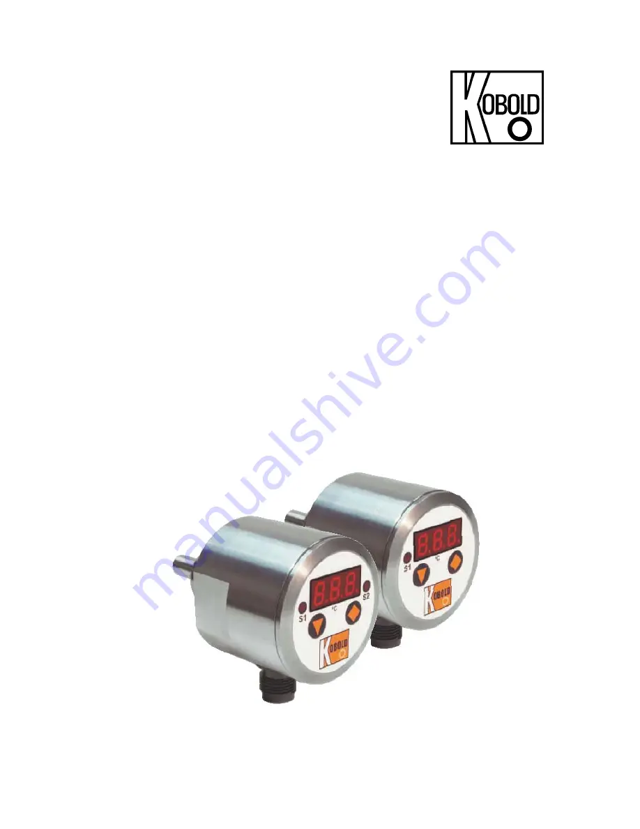
Electronic Temperature Switch
Model: TDD
Page 1: ...Operating Instructions for Electronic Temperature Switch Model TDD...
Page 2: ...10 2 Adjustments for TDD 5 TDD 7 10 11 Main Menu Options 12 11 1 Switching point 12 11 2 Hysteresis 12 11 3 Window point Double Point only for TDD 1 and TDD 3 12 11 4 Switching behaviour 13 11 5 Filte...
Page 3: ...ument Inspection Instruments are inspected before shipping and sent out in perfect condition Should damage to a device be visible we recommend a thorough inspection of the delivery packaging In case o...
Page 4: ...ice is in agreement with your system requirements specifications Ensure that the maximum operating pressure or temperature for the device is not exceeded Installation This device is installed in a mat...
Page 5: ...ke sure that the electrical supply lines are de energised Make the connection using the M 12x1 connector socket as shown in the accompanying diagram Appropriate connectors with different cable lengths...
Page 6: ...16 7 2 Connector pin assignment TDD 553 TDD 753 TDD 553 TDD 753 PNP Output 1 NPN Output 1 24 VDC 24 VDC 0 V GND 0 V GND PNP Output 2 NPN Output 2 0 V GND 0 V GND Plug PNP connection scheme Plug NPN Co...
Page 7: ...lements within the unit may become very hot Connect the temperature switch according to the figure shown on the previous page and supply the device with the specified voltage 8 1 Button function In th...
Page 8: ...t 1 2 4 8 16 32 64 1 Contact Type Con Contact N O or N C N O Contact Code CCo change code 000 999 000 9 1 Value setting From main menu option e g Switching point SPo press key in order to go to Parame...
Page 9: ...20 sec Don t press any key Next level Change value Contact type N O contact N C contact Save Off delay Setting parameter Setting parameter On delay Duo point Hysteresis Switch point Code input 3 sec C...
Page 10: ...416 10 2 Adjustments for TDD 5 TDD 7 Setting parameter On delay 2 On delay 1 Setting parameter Setting parameter Hysteresis 2 Hysteresis 1 Switch pt 2 Setting parameter Switch pt 1 Code input 3 sec Co...
Page 11: ...TDD TDD K06 0416 page 11 Change code Setting parameter Contact type 2 N O contact N C contact Save Contact type 1 N O contact N C contact Save Off delay 2 Off delay 1 Setting parameter...
Page 12: ...e hysteresis The hysteresis relates to the switching point and the window point switching point minus hysteresis window point plus hysteresis Example Switching point 100 C Hysteresis 2 5 C The tempera...
Page 13: ...es back 11 4 Switching behaviour The following diagram clarifies the switching behaviour of the temperature switch The contact closes contact type no when it drops below the switching point or the win...
Page 14: ...ated overshoot detector reacts to a step change of approx 6 25 of the measurement range full scale During a detected measured value overshoot of 6 25 the instantaneous measured value is transferred di...
Page 15: ...hing point N C contact means Contact opens on exceeding the switching point 11 8 Change Code The code change CCo protects the device against unauthorised changes in adjusted device parameters If the c...
Page 16: ...of measured medium 20 120 C compact version 50 125 C separate version Max ambient temp 20 50 C Max pressure 80 bar Power supply 24VDC 20 Current intake TDD 1 3 5 7 approx 50 mA without switching outp...
Page 17: ...TDD 153 TDD 353 TDD 553 TDD 753 R4H2 G 1 2 20 120 C R5H2 G 3 4 20 120 C N4H2 1 2 NPT 20 120 C N5H2 3 4 NPT 20 120 C D6H3 separate version smooth sensor 50 125 C 00 short 10 100 mm 20 200 mm Separate v...
Page 18: ...TDD page 18 TDD K06 0416 15 Dimensions Compact version short Compact version long Separate version...
Page 19: ...al equipment for measurement control and laboratory use EMC requirements Part 1 General requirements EN 61010 1 2011 Safety requirements for electrical equipment for measurement control and laboratory...