

VFS-FR2
Instruction Manual
Read me first
Features
Technical spec
Installing method
ESC connections.
Set up
This display shows the content where the possibility of owing the death or the serious injury is assumed, and a disadvantageous accident can occur at high frequency.
This display shows the content to which a possibility and/or a disadvantageous accident may occur causing injury.
Warning!
Warning!
Warning!
Attention!
Attention!
Attention!
When mishandling a RC model it is very dangerous. This type of matter should be especially noted to avoid and should be usedsafely as much as possible.
Warning and attention are displayed in this book, the explanation of the display and the sign should be especially paid attention to.
Important
The standard and its setting are memorized by the signal from the transmitter in VFS-FR2. The settings are memorizes and do not disappear even if the power supply is turned off.
Operation of throttle mode and reverse
Communication mode
Receiver
Power on/off switch
Set button
LED
Thank you for purchasing this product. Please read this manual to make the best use of the performance
of the VFS-FR2 and enjoy RC. Also, please use it accordingly when there are displays of warning and
attention, etc. and for safety. Please keep in mind the cautions after you have read these instructions.
This controller is a high performance model equipped with a configurable variable frequency system (VFS) depending on the throttle
position.
The frequency setting width is 5.3KHz-460Hz. 64 different frequency settings can be set in each step across the slide area of 32 steps.
Recommended VFS curve is installed in a shipment state.
Recomended turns of motor, [LiPO]up to 12turns, [LiFe/NiMH]up to 23turns.
※
When using a higher power motor, please change the ICS setting.
It is also possible to set the feeling of your choice to suit the battery and use motor when you change the settings in the ICS.
The brushed motor is for exclusive use.
Only two wiring motors acceptable.
※
A brushless motor (motor wiring three motors) is not available.
Supported various chargable batteries including
Li-Po, Li-Fe, Ni (6.6 - 8.4v)
※
In a factory setting, VFS-FR2 suitable for a Li-PO battery.
Adjusted power save voltage setting at 5.5v.
This functions occer power save at 6v, then motor stop at 5.5v.
●
Control method: Changeable control
●
The maximum peak current: 1200A (FET specs.)
●
Continuous, maximum current:300A (FET specs.)
●
Proper operating voltage:
6.6-8.4V (LIxx 2cells, NIxx6cells)
●
Drive frequency: 0.56-5.3KHz(64steps) initialization 4.0kHz
●
Output voltage for receiver: 6V (input 7.2v)
●
Output current for receiver:
3A (Peak)
●
SIze:32.6×29.0×19.4mm (size of case)
●
25.3g in weight (The silicon wire excluded.)
Reciever
Please install the reciever and antenna wire
to be isolated from noise sources.
Noise
●
Efficiency will be lowered if the termperature is extreme. Ensure the flow of air to
prevent extreme temperatures.
●
In preparation for a crash, the equipment should be installed in a safe position.
VFS-FR2 is fixed to the chassis plate with the double-sided tape. Install the switch in a position where it can be
easily operated.
※
Please mount with double-sided tape in a location that will be free from dust, moisture, oil, etc.
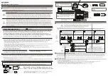
Connect it to channel 2 of the receiver slot.
●
Always turn on the transmitter first, then turn on the speed controller's
power.
●
After speed controller's power supply is turned off, then the power
supply of the transmitter should be turned off.
※
The receiver will pick up noise when the order is reversed.
This may cause the car to go out of control and may cause
an unexpected accident.
Please do not connect the wire for
the motor until standard setup is
completed.
Connect it the negative side of
the motor.
Connect it the positive side of
the motor.
Connect it to the positive side of the
battery.
Receiver connector
●
Before the setting
■
The battery for the transmitter and the battery in the car should be charged before use.
■
The speed controller should be connected referring to the preceding instructions.
■
The switch of the transmitter should be
turned on first.
■
Factory setting of the throttle trigger on the transmitter should be assigned. (Original setting when it was shipped)
■
When the KO transmitter is shipped, the setting is 100% for the brake and throttle trim
is neutral. Please make it to turn off ABS and Acceleration functions that are provided
in the transmitter.
ON
Hold down
Flash
Push
Flashing
2 times
Flashing
4 times
Flashing
once
Flashing
3 times
①
Connect the 2-wire cable (white and black), ICS USB adapter(HS) and VFS-FR2 receiver connector.
②
Connect a battery pack to VFS-FR2.
③
Hold down the set button while switching the power to the on position. Hold the button down until the LED light comes on and data
communication with VFS-FR Manager Ver1.2 is possible in this state.
Neutral Setting
Nutral
setting
Forward Setting
Forward
Setting
Brake Setting
Brake
Setting
※
Battery connector and motor connector solder by manufacture.
※
Generally, the number of turns of a motor and the load to the speed controller are not necessarily related. Although it is possible to use a motor as long as it is marketed
for electric cars. According to the usage condition, the thermal protector works regardless of the number of turns. Please decrease the load by changing the gearing,
timing, motor etc. when the thermal protector is engaged.
OFF
ON
●
Please set-up the standard (Factory Default Setting) for the transmitter in the beginning.
This will not operate properly if the standard is not set.
●
Please do not connect the motor when you set the standard. (Please connect it after all settings are done.)
Throttle
position
Power on/off
switch
Set button
LED
Hold down the set button while switching the
power to the on position. Hold the button down
until the LED light comes on and release.
The LED light will repeat a
pattern of flashing once.
Leave the throttle trigger in
the neutral position and press the set
button once.
The LED light will repeat a
pattern of flashing two times.
The throttle trigger should be
pulled to the full forward position and
held while the set button should be
pushed once.
The LED light repeats a pattern of
blinking three times. The throttle trigger
is pushed to the full brake position and
held while pushing the set button once.
Setting of throttle mode
The LED light will repeat a pattern of
blinking four times. The throttle mode
is set at the position of the throttle
trigger and held while pushing the set
button once.
LED light comes on
release botton
Hold the button down during the
throttle trigger holding.
Hold the button down during the throttle
trigger holding.
Hold the button down during the throttle
trigger holding.
When a standard setting is completed, the LED will remain on and throttle
will operate.
※
It doesn't light according to the throttle position.
※
When the power on/off switch is cut before a standard setting
is not memorized, you will need to perform the setting of the
standard setup of the speed controller again.
※
The braking feature will operate on the VFS-FR when moving the throttle trigger from the forward position to the braking position in the standard setup. Reverse will only be engaged by returning to the neutral
position after braking, then moving to the reverse position. When reversing and you are not in the neutral position, forward will not work. Moreover, please note that reverse might not start well when a neutral
position is adjusted by the trim of the transmitter after it has been set.
※
Repeated brake operation or pumping of the brakes, the VFS-FR2 may begin the reverse function suddenly. In this case please use the reverse disabled mode.
※
The load to the motor and the speed controller might increase when changing to the linear reverse setting. The thermoheat protector may engage early. Please use it after it has cooled down.
The standard setting is is completed with the above steps. When
not in use, please turn OFF the power switch of the VFS-FR2.
Battery
Motor
○
This product is manufactured and sold for the RC model ground use only. - Please do not use it for anything else.
○
Make sure the connector of the servo, speed controller, etc. is properly inserted into the
receiver. - There is a possibility of driving recklessly when the connector(s) become disconnected due to the vibration during operation.
○
When using 27/40MHz transmitter, always turn on your transmitter first
before turning on the speed controller to make sure the band (frequency) is not being used. - Operating on a "in use" band (frequency) is dangerous and reckless.
○
Do not operate during thunder or electrical
storms. - Lighting may strike the antenna of the transmitter.
○
Do not operate when it is raining or there is standing water. - If water enters the equipment, you will lose control and drive recklessly.
○
If you are tired,
drinking alcohol, or are under medication, do not operate this equipment. - An unexpected accident is maybe caused by the lack of judgment.
○
After a run, disconnect and remove the battery. - When the switch
is turned on by mistake, the model can drive recklessly and can catch on fire.
○
The transmitter, the battery, and the model, etc. should be kept in the place where children cannot reach. - The danger of poisoning,
burn, and injury may occur by accidental ingestion.
○
Do not make a mistake in the polarity connection of the battery. - The equipment will be damaged.
○
The transmitter, receiver, servo, and other option parts used should only be genuine KO PROPO products. - Our
company cannot assume the responsibility of damage etc. that occur because of the combination of nongenuine KO PROPO products.
○
When turning on the power supply do it in this order (transmitter
→
speed
controller). Turning off the power in this order (speed controller
→
transmitter). - When the order is reversed, the receiver will pick up noise and may go out of control.
○
After operation, do not touch hot surfaces
such as the motor and the speed controller. - Caution combustible.
○
Please do not short-circuit the leads like the battery wire and the motor wire etc. of this product. - The equipment will be damaged.
○
Please
remove or disconnect the motor when you set up this product.
○
Please do not operate this on the street or where people are present.
○
Please send this to our service department when there is damage or when this
product gets wet. - It may cause corrosion and the breakdown of the product.
○
Please avoid high impacts to this product. - It may cause damage.
○
Please read the manual thoroughly before using this product and
keep it handy for future references. Please inquire of ourservice depart when you cannot understand the manual.
Connect it to the negative
side of the battery.
Black
Brakes are working but the reverse
function is turned off.
The brake and the reverse
operation of the standard setup.
Only the reverse operation is on without
the brake.
A
B
C
Reverse is disabled.
standard
Linear reverse
Various parameters can be set by ICS (Interactive Communication System) besides the drive frequency.
①
Frequency of brake: Initialization is about 5.0KHz. The brake frequency can be changed to 64 different frequencies ranging from 460Hz-5.3KHz.
②
Throttle mode setting: The operation of the brake and reverse can be selected from three modes.
③
The power save voltage: The power supply output supplied to the receiver can be set while maintaining a constant voltage. This allows for a
steady to the last minute run.
④
Throttle response: The throttle operation of the beginning grasp can be changed to be mild. This combined with the punch function of the
transmitter can have your car start like a rocket. This especially benefits if the surface conditions are slippery.
⑤
Current limiter: A large current to the motor can be suppressed. A set value OFF is also possible. This setting aids in extending runtime by not
over using the current that you would need.
※
To change a frequency or another setting of VFS-FR2; with No. 61028 ICS USB adapter HS and OS after Windows XP or latest PC, other selling
PC software VFS-FR manager V1.2 (download from KOPROPO HP) is necessary. (We cannot guarantee the using in Windows8.)
Please affix a settled sticker to the
top and sides.
Black
Red
VFS-FR Manager download in a below URL.
http://www.kopropo.co.jp/en/supports/view/171
Also, when you download the recommended data from the KOPROPO home page , you can experience the VFS immediately . ( From time to time will be released )
※
When wait with pushing the set button; a process of the once
blinking Jump; and of the twice is flashed on and off. please
advance to 3.
VFS ( Variable Frequency System
)
ICS ( Interactive Communication System
)
(※
The patent has been acquired.
)
PAT.
●
Connector should be properly installed.
※
Vibrations while using this product may
cause theconnector to come lose and
you will lose control of the vehicle.
1
2
3
4
5
6
1. neutral
2. forward high point (full throttle)
3. brake maximum (reverse)
Red


