The controller or amp-controller should be fully installed with speakers
to test it and set the gain. We suggest that the DC101 gain be turned
down before testing the door chimes.
Using the provided PS1202 power supply connect the power supply to
the DC101 and plug the power supply into full time unswitched power.
If the power is switched off then the door chimes will not work!
Do not terminate or connect unused detachable terminal connections.
Turn the controller or controller amp on to standby and any extra
amps connected into the system. Have someone push the door button
and listen to the level. Adjust it as desired. After adjusting the level it
is important to check all of the other zones to hear if they are being
overloaded by the chime sound. If they are, then the DC101 gain (of
the whole system) has to be lowered.
If this installation has more than one controller and/or controller-amp
use good quality Y cords to connect each of the controller Source 4
jacks (in parallel) to the DC101 stereo jacks labeled out.
If the Source 4 input on the controller or controller amp is not being
used skip the rest of this paragraph. If you are still reading this, then
connect the stereo source input planned for Source 4 to the “In” RCA
jacks on the DC101 chime module.
Next connect the DC101 data port to the controller or controller-amp
data port using the supplied 3.5mm stereo jack/cable.
If two buttons are connected to the same detachable terminals, the
DC101 will chime the same for the two buttons. It also may not
provide enough power for lighted buttons.
Connect the last conductor to the last open terminal on the
detachable connector.
Connect the conductor of the next button to one of the two open
positions on the detachable connector.
Next connect the DC101 “Out” RCA jacks to the controller or
controller-amp Source 4 inputs using a gold stereo RCA wire.
Connecting the DC101 to the amp or controller
Running wire
Any conventional two-conductor wire is adequate for most
installations. Runs longer than 100 feet (33 meters) should use
minimum 18-gauge wire, as the power to the lighted door buttons will
be limited. Run a home run from each of the up to three door button
locations to the DC101.
Connect the wires and install the door button as the manufacturers
instructions advise.
Caution
: In retrofit applications make sure the “old” power
supply is disconnected from the door button wires or major
system damage could occur.
Connecting door buttons to the DC101
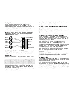
The detachable four-position connector on the DC101 is connected to
the up to three door chime buttons. Each of the three positions run
two different chime sounds depending on the bank position switch.
Chime Sounds
All three chime sounds have to come from the same bank (in or out).
Bank
A-out B-out A-in B-out
A-out B-in
A-in B-out
Front
Big ben
2 chimes
Knock x 4
Big ben
Rear
Chimes
Ding
Knock x 3
2 chimes
Side
½ big ben
Chimes
Knock x 2
Knock x 3
Connect one of each of the up to three wires from each of the door
buttons to the detachable connector labeled “Ground”. Most lighted
door buttons do not have polarity.
Connect the conductor of one of the door buttons to front, rear or side
position of the detachable DC101 connector.
DC101 Power
Setting the gain.
Front
Rear
Side
Ground
Front
button
Rear
button
Side
button
DC101 Connector


