background image


Installation & Operation Manual

13

2  

Prepare boiler 

(continued)

FASTENERS 
APPROPRIATE
FOR WALL TYPE
QTY: 4

MOUNTING BRACKET
(FACTORY SUPPLIED)

WALL:
WOOD OR METAL STUDS ON 
16" CENTERS
-OR- 
MASONRY / POURED CONCRETE

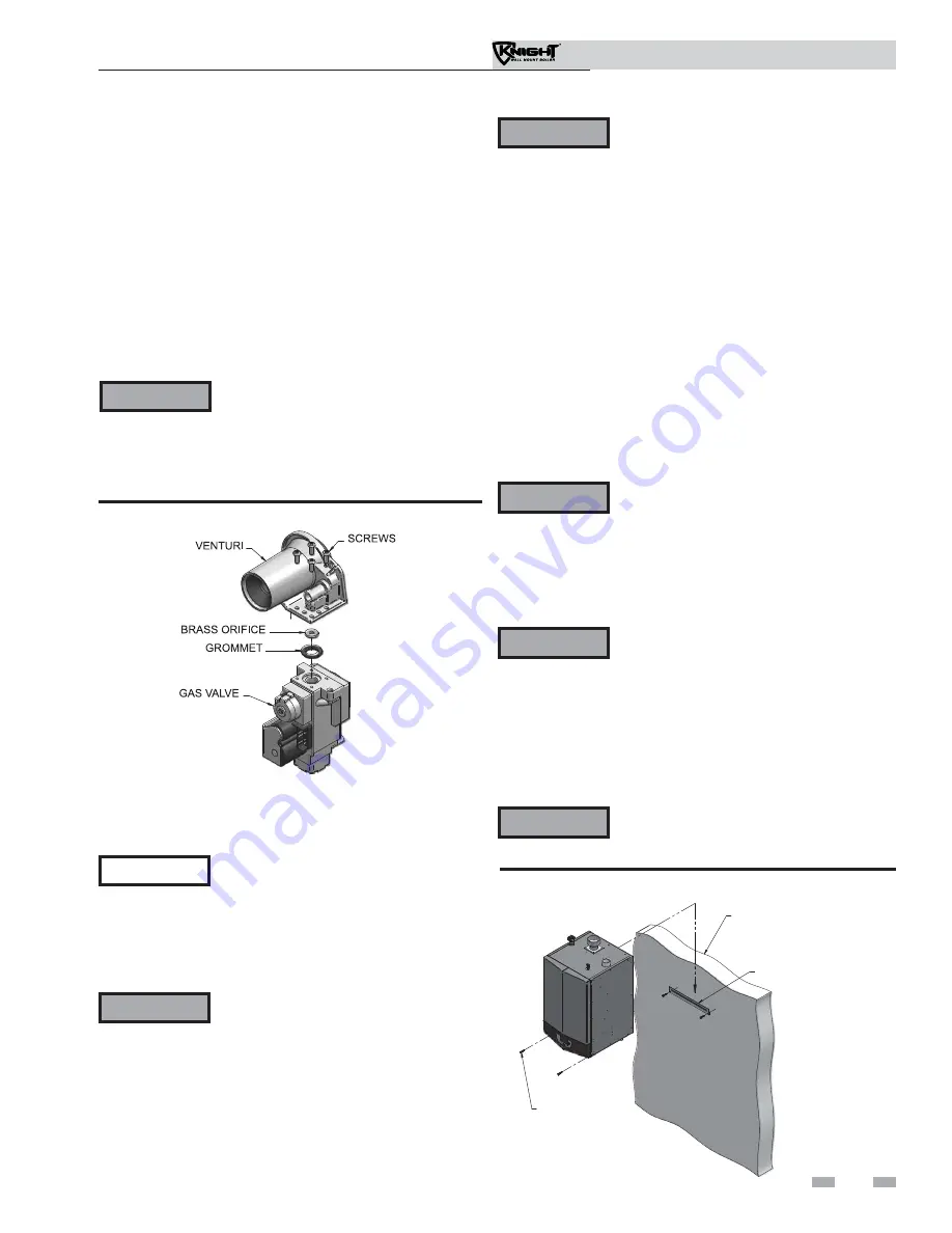
Figure 2-4 Mounting the Boiler

Figure 2-3 Installing Propane Orifice 

13.  Reattach the wiring connector to the gas valve.  Tighten 

the screw on the wiring connector to secure to the gas 
valve.

14.  Turn the gas valve power switch to the “ON” position.

15.  Reattach the bezel to the unit.  Reconnect the ribbon cable 

to the control board.

16.  After installation is complete, fill out the gas conversion 

label (in the conversion kit bag) and affix it to the unit 
under the boiler rating plate inside the unit.  Attach the 
LP caution label (in the conversion kit bag) to the left side 
of the unit in the lower left corner.

17.  Replace the front access cover.

2.  Mount the wall bracket using the 2 1/4" lag bolts 
 

provided.  Make sure the top edge of the bracket is away 


from the wall.  Ensure the bracket is level when mounted.  


Extreme care is needed to ensure the bolts are secured in 


the center of the studs.

3.  Hang the boiler on the bracket and secure the bottom of 
 

the boiler with two (2) additional lag bolts provided.

Mounting to a metal studded wall:

1.  The wall mount bracket is designed for a stud spacing of 
 

16 inches from center.  For other stud spacing a solid 


mounting surface must be provided by the installer.

 WARNING

The boiler is too heavy for a single person 
to lift.  A minimum of two people is needed 
for mounting the boiler onto the bracket.

2.  Mount the wall bracket using two (2) field supplied toggle 
 

bolts capable of supporting 100 pounds each.  Ensure the 


top edge of the bracket is away from the wall.  Ensure the 


bracket is level when mounted.  Extreme care is needed to 


ensure the bolts are secured in the center of the studs.

3.  Hang the boiler on the bracket and secure the bottom of the 
 

boiler with two (2) field supplied toggle bolts.

 WARNING

Do not mount the boiler to a hollow wall.  Be 
sure to mount the boiler to the studs only.

Mounting the boiler

See page 9 of this manual for boiler mounting location 
instructions.

 NOTICE

The Knight Wall Mount boiler is not 
intended for floor installation.

Mounting to a wood studded wall:

1.  The wall mount bracket is designed for a stud spacing of 
 

16 inches from center.  For other stud spacing a solid 


mounting surface must be provided by the installer.

 WARNING

Do not mount the boiler to a hollow wall.  
Be sure to mount the boiler to the studs 
only.

Mounting to a concrete wall:

1.  Mount the wall bracket using the two (2) wedge anchor 
 

bolts provided with the bracket.  To mount the wedge 


anchor bolts, drill a 1/4" diameter hole 1 1/8" deep and 


insert anchor.  Hang the bracket from the anchor and secure 


with the two nuts provided.  Make sure the top edge of the 


bracket is away from the wall.  Ensure bracket is level when 


mounted.  Extreme care is needed to ensure the bolts are 


secured in the center of the studs.

Note:

  If wall thickness does not allow a 1 1/8" deep hole, 

field supplied hardware suitable for the application should be 
provided.

2.  Hang the boiler on the bracket and secure the bottom of the 
 

boiler with two (2) remaining anchors, following the 

 instructions 

above.

 WARNING

The boiler is too heavy for a single person 
to lift.  A minimum of two people is needed 
for mounting the boiler onto the bracket.

 WARNING

After converting to LP, check combustion 
per the Start-up procedure in Section 10 
of this manual.  Failure to check and 
verify combustion could result in severe 
personal injury, death, or substantial 
property damage.

 WARNING

The boiler is too heavy for a single person 
to lift.  A minimum of two people is needed 
for mounting the boiler onto the bracket.

Summary of Contents for WBN051

Page 1: ...ting installer service technician Read all instructions including this manual and the Knight Wall Mount Service Manual before installing Perform steps in the order given Failure to comply could result in severe personal injury death or substantial property damage WARNING Save this manual for future reference ...

Page 2: ...nstall Vent and Combustion Air Piping 15 Requirements for Installation in Canada 16 Sizing 16 Min Max Combustion Air Vent Piping Lengths 16 Materials 17 Optional Room Air 18 PVC CPVC 19 Polypropylene 20 Stainless Steel Vent 21 4 SIDEWALL DIRECT VENTING Vent Air Termination Sidewall 22 25 Determine Location 22 23 Prepare Wall Penetrations 24 Multiple Vent Air Terminations 25 Sidewall Termination Op...

Page 3: ... heat exchanger and causes failure Addition of oxygen carried in by makeup water can cause internal corrosion in system components Leaks in boiler or piping must be repaired at once to prevent makeup water Freeze protection fluids NEVER use automotive antifreeze Use only inhibited propylene glycol solutions which are specifically formulated for hydronic systems Ethylene glycol is toxic and can att...

Page 4: ...ge of firing rates 13 Water outlet system supply The water outlet is the water connection for water leaving the boiler and entering the system Boiler connection is 1 14 Water inlet system return The water inlet is the water connection for water entering the boiler from the system Boiler connection is 1 15 Gas connection pipe Threaded pipe connection of 1 2 This pipe should be connected to the inco...

Page 5: ...7 19 23 10 28 Front View 16 33 20 29 31 3 13 14 7 27 8 6 Left Side inside unit 2 25 24 5 4 26 22 18 1 Right Side inside unit The Knight Wall Mount Boiler How it works continued FRONT OF UNIT 14 13 30 21 15 22 Bottom View 5 Models 51 211 ...

Page 6: ...peration but the operation given in this manual remains the same as the standard boilers A high altitude label as shown in FIG A is also affixed to the unit Maximum allowed working pressure is located on the rating plate NOTICE Knight Wall Mount Boiler AHRI Rating Model Number Note Change N to L for L P gas models Input MBH Note 5 Min Max Heating Capacity MBH Note 2 8 Net AHRI Ratings Water MBH No...

Page 7: ...system and boiler to freeze and leak WARNING This appliance is certified as an indoor appliance Do not install the appliance outdoors or locate where the appliance will be exposed to freezing temperatures or to temperatures that exceed 100 F Failure to install the appliance indoors could result in severe personal injury death or substantial property damage Provide clearances Clearances from combus...

Page 8: ...ER HOUR INPUT WITH A MINIMUM OF 100 SQ INCHES VENTILATING AIR OPENING RIGHT 0 MINIMUM Figure 1 1 Closet Installation Minimum Required Clearances WARNING For closet installations CPVC or stainless steel vent material MUST BE used in a closet structure due to elevated temperatures Failure to follow this warning could result in fire personal injury or death Note Service clearances are recommendations...

Page 9: ...B149 Installation Code Appliances located in residential garages and in adjacent spaces that open to the garage and are not part of the living space of a dwelling shall be installed so that all burners and burner ignition devices are located not less than 18 inches 46 cm above the floor The appliance shall be located or protected so that it is not subject to physical damage by a moving vehicle Ven...

Page 10: ...e collar connection Size To ensure proper pipe size is in place see Table 3A Check to see that this size is used throughout the vent system Manufacturer For a stainless steel or polypropylene application you must use only the listed manufacturers and their type product listed in Tables 3E and 3G for CAT IV positive pressure venting with flue producing condensate Supports Non combustible supports m...

Page 11: ... and any appliance not connected to the common venting system Turn on any exhaust fans such as range hoods and bathroom exhausts so they will operate at maximum speed Do not operate a summer exhaust fan Close fireplace dampers d Place in operation the appliance being inspected Follow the lighting instructions Adjust thermostat so appliance will operate continuously e Test for spillage at the draft...

Page 12: ...itch to the OFF position FIG 2 2 4 Disconnect the Molex plug from the wiring connector located on the gas valve 5 Using a 5 16 nut driver loosen the band clamp securing the air intake coupler to the gas valve venturi Remove the air intake pipe and coupler from the gas valve venturi 6 Using a 4mm Allen wrench remove the two 2 screws securing the gas valve venturi to the inlet of the combustion blow...

Page 13: ...care is needed to ensure the bolts are secured in the center of the studs 3 Hang the boiler on the bracket and secure the bottom of the boiler with two 2 field supplied toggle bolts WARNING Do not mount the boiler to a hollow wall Be sure to mount the boiler to the studs only Mounting the boiler See page 9 of this manual for boiler mounting location instructions NOTICE The Knight Wall Mount boiler...

Page 14: ...mination See page 26 for more details Direct venting options Sidewall Vent Figure 3 3 Two Pipe Vertical Termination See page 29 for more details Figure 3 5 Vertical Vent Sidewall Air Direct venting options Vertical Vent Figure 3 4 PVC CPVC Concentric Vertical Termination See page 31 for more details 14 Installation Operation Manual ...

Page 15: ...l connection Combustion air piping must be supported per guidelines listed in the National Mechanical Code Section 305 Table 305 4 or as local codes dictate 2 Vent Connector FIG s 3 7 thru 3 9 Used to provide a passageway for conveying combustion gases to the outside A transition fitting is provided on the unit for final connection Vent piping must be supported per the National Building Code Secti...

Page 16: ...n air and vent piping lengths are as follows Combustion Air 12 equivalent feet minimum 100 equivalent feet maximum Vent 12 equivalent feet minimum 100 equivalent feet maximum When determining equivalent combustion air and vent length add 5 feet for each 90 elbow and 3 feet for each 45 elbow EXAMPLE 20 feet of PVC pipe 4 90 elbows 2 45 elbows 1 concentric vent kit CVK3003 49 equivalent feet of pipi...

Page 17: ...pe meeting UL Standard 723 or 181A P or a high quality UL Listed silicone sealant such as those manufactured by Dow Corning or General Electric b Do not install seams of vent pipe on the bottom of horizontal runs c Secure all joints with a minimum of three 3 sheet metal screws or pop rivets Apply Aluminum Foil Duct Tape or silicone sealant to all screws or rivets installed in the vent pipe d Ensur...

Page 18: ...Please review Section 1 Prevent Combustion Air Contamination to ensure proper installation Vent system and terminations must comply with the standard venting instructions set forth in this manual WARNING When utilizing the single pipe method provisions for combustion and ventilation air must be in accordance with Air for Combustion and Ventilation of the latest edition of the National Fuel Gas Cod...

Page 19: ...ll PVC vent pipes must be glued properly supported and the exhaust must be pitched a minimum of a 1 4 inch per foot back to the boiler to allow drainage of condensate NOTICE WARNING The vent connection to the appliance must be made with the starter piece provided with the appliance if PVC CPVC vent is to be used The field provided vent fittings must be cemented to the CPVC pipe section using an Al...

Page 20: ...ly with listed options in this manual and be a single wall vent offering For use of flex pipe it is recommended to have the vent material in 32 F or higher ambient space before bending at installation No bends should be made to greater than 45 and ONLY installed in vertical or near vertical installations For support and special connections required see the manufacturer s instructions All vent is t...

Page 21: ... manufacturers listed in Table 3G Use only the materials vent systems and terminations listed in Tables 3G and 3H DO NOT mix vent systems of different types or manufacturers Failure to comply could result in severe personal injury death or substantial property damage WARNING Installations must comply with applicable national state and local codes Stainless steel vent systems must be listed as a UL...

Page 22: ...old air Avoid areas where the plume could obstruct window views c Prevailing winds could cause freezing of condensate and water ice buildup where flue products impinge on building surfaces or plants d Avoid possibility of accidental contact of flue products with people or pets e Do not locate the terminations where wind eddies could affect performance or cause recirculation such as inside building...

Page 23: ...al Stainless Steel Sidewall Termination of Air and Vent w Field Supplied Fittings Figure 4 3A Clearance to Forced Air Inlets Installation Operation Manual 5 Maintain clearances as shown in FIG s 4 1A thru 4 3B pages 22 23 Also maintain the following a Vent must terminate At least 6 feet from adjacent walls No closer than 12 inches below roof overhang At least 7 feet above any public walkway At lea...

Page 24: ... air gaps 6 Assemble the vent cap to the vent plate see FIG s 4 4A and 4 4B Insert the stainless steel screws into the vent cap screw hole openings and securely attach the vent cap to the vent plate 7 Seal all wall cavities 8 PVC CPVC terminations are designed to accommodate any wall thickness of standard constructions per the directions found in this manual 9 Stainless steel terminations are desi...

Page 25: ...G 4 5A for U S installations For Canadian installations provide clearances required by CSA B149 1 Installation Code 3 The air inlet of a Knight wall mount boiler is part of a direct vent connection It is not classified as a forced air intake with regard to spacing from adjacent boiler vents WARNING 12 MIN BETWEEN EDGE OF AIR INLET AND ADJACENT VENT OUTLET VENT AIR TERMINATION VENT AIR Figure 4 5A ...

Page 26: ...Kit Contents Sidewall termination installation 1 Determine the best location for the termination kit see FIG 4 6 2 Reference the Determine Location Section on page 22 of this manual for general termination considerations 3 Cutone 1 hole 5inchdiameterfor CVK3003installations or 4 inch diameter for CVK3008 installations into the structure to install the termination kit 4 Partially assemble the conce...

Page 27: ... result in product damage or improper operation personal injury or death Figure 4 9 Rain Cap to Vent Pipe Alternate Assembly 5 Install the Y concentric fitting and pipe assembly through the structure s hole Do not allow insulation or other materials to accumulate inside the pipe assembly when installing through the hole 6 Install the rain cap and small diameter pipe assembly into the Y concentric ...

Page 28: ...1 It is important that vent terminations be made as shown to avoid recirculation of flue gases VENT COMBUSTION AIR 12 MINIMUM Figure 4 11 Concentric Vent and Combustion Air Termination Figure 4 10 Concentric Vent Sidewall Attachment DO NOT use field supplied couplings to extend pipes Airflow restriction will occur and may cause intermittent operation 8 Cement appliance combustion air and vent pipe...

Page 29: ... the air termination elbow FIG 5 1A by inserting bird screens Bird screens should be obtained locally 3 The vent must terminate at least 3 feet above the highest place in which the vent penetrates the roof and at least 2 feet above any part of a building within 10 horizontal feet 4 The air piping must terminate in a down turned 180 return pipe no further than 2 feet from the center of the vent pip...

Page 30: ...ntake with regard to spacing from adjacent boiler vents Figure 5 2 Vertical Terminations with Multiple Boilers Figure 5 3 Alternate Vertical Terminations with Multiple Boilers WARNING 30 Installation Operation Manual Prepare roof penetrations 1 Air pipe penetration a Cut a hole for the air pipe Size the air pipe hole as close as desired to the air pipe outside diameter 2 Vent pipe penetration a Cu...

Page 31: ...ogether when field disassembly is desired for cleaning see FIG 4 9 page 27 When using the alternate screw assembly method drill a clearance hole in the rain cap and a pilot hole in the vent pipe for the screw size being used Failure to drill adequate holes may cause cracking of PVC components allowing combustion products to be recirculated Failure to follow this warning could result in personal in...

Page 32: ...ical terminations When two 2 or more direct vent appliances are vented near each other each appliance must be individually vented see FIG 5 7 NEVER common vent or breach vent this appliance When two 2 or more direct vent appliances are vented near each other two 2 vent terminations may be installed as shown in FIG 5 7 It is important that vent terminations be made as shown to avoid recirculation o...

Page 33: ...on must comply with local requirements and with the National Fuel Gas Code The maximum allowable equivalent vent and air intake lengths for this venting arrangement are to be determined from the General Venting Section If an existing unused venting system is converted for use with this method of concentric venting the installer must ensure that the existing venting system is clean and free from pa...

Page 34: ...5 Vertical direct venting Existing vent as a chase Follow all existing termination and clearance requirements and allowable pipe lengths Use only approved venting materials listed in the General Venting Section of this manual 34 For concept illustration only Individual installations may vary due to job site specific equipment ...

Page 35: ... through 6 10 which will guide you through the installation of the Knight wall mount boiler reference FIG s 6 1A and 6 1B 1 Connect the system return marked Inlet 2 Connect the system supply marked Outlet 3 Install purge and balance valve or shutoff valve and drain on system return to purge air out of each zone 4 Install a backflow preventer on the cold feed make up water line 5 Install a pressure...

Page 36: ...ef valve Factory supplied The pressure relief valve is sized to ASME specifications 11 Boiler purge valve Field supplied The boiler purge valve is used to remove entrapped air from the heat exchanger during start up 12 System temperature sensor Lochinvar supplies a system temperature sensor The sensor is to be installed in the heating loop downstream from the boiler hot water piping and heating lo...

Page 37: ...SYSTEM SENSOR DRAIN TYPICAL SYSTEM PUMP LOW LOSS HEADER TYPICAL CONDENSATE DRAIN INDIRECT DOMESTIC HOT WATER TANK Y STRAINER RECOMMENDED DRAIN VALVE BOILER PUMP FILL VALVE EXPANSION TANK TO SYSTEM FROM SYSTEM FROM TO DOMESTIC HOT WATER PUMP AIR SEPARATOR SYSTEM SENSOR Figure 6 1B Near Boiler Piping w Low Loss Header 6 Hydronic piping continued Circulator sizing The Knight wall mount boiler heat ex...

Page 38: ... UPS15 58FC 0014 NRF 36 E7 106 7 7 17 5 1 UPS26 99F 0014 NRF 36 E7 151 11 0 12 8 1 UPS26 99F 0014 NRF 36 E7 211 15 5 19 0 1 UPS26 99F 0013 NRF 36 E7 35 F Temperature Rise Applications Model GPM FT HD Minimum Pipe Size Pump Grundfos TACO B G Armstrong 51 2 9 4 1 1 UPS15 58FC 007 NRF 22 Astro 30 81 4 2 7 3 1 UPS15 58FC 007 NRF 22 Astro 30 106 5 5 9 8 1 UPS15 58FC 007 NRF 22 Astro 30 151 7 9 10 1 UPS...

Page 39: ... pump listed in the shaded area in Table 6B to the boiler high voltage terminal strip Variable speed pump setup Before operation ensure the following Pump is set for an input signal of 0 10Vdc by the dip switches on the pump control Pump is set for external signal control if applicable Pump is set for linear output if applicable If pump does not come equipped with a 0 10 Vdc input option an option...

Page 40: ...ER HOT WATER OUT ZONE CIRCULATORS TYPICAL FLOW CHECK VALVE TYPICAL BOILER CIRCULATOR SYSTEM SUPPLY SENSOR PRESSURE RELIEF VALVE Y STRAINER RECOMMENDED MAY SUBSTITUTE LOW LOSS HEADER NOT TO EXCEED 4 PIPE DIA OR MAX OF 12 APART ZONE 1 ZONE 2 ZONE 3 ZONE 4 Figure 6 3 Single Boiler Single Temperature Zoned with Circulators Please note that these illustrations are meant to show system piping concept on...

Page 41: ...LER 1 LEADER SYSTEM SUPPLY SENSOR TEMPERATURE PRESSURE GAUGE DRAIN Y STRAINER RECOMMENDED TYPICAL MAY SUBSTITUTE LOW LOSS HEADER ZONE 1 ZONE 2 ZONE 3 ZONE 4 Figure 6 4 Multiple Boilers Single Temperature Zoned with Circulators Model Number of Units 2 3 4 5 6 7 8 Required Pipe Sizes 51 1 1 1 4 1 1 2 2 2 2 2 81 1 1 4 1 1 2 2 2 2 1 2 2 1 2 2 1 2 106 1 1 2 2 2 2 1 2 2 1 2 2 1 2 3 151 2 2 2 1 2 2 1 2 3...

Page 42: ...ITUTE LOW LOSS HEADER TEMPERATURE LOOP 1 TEMPERATURE LOOP 2 TEMPERATURE LOOP 3 NOT TO EXCEED 4 PIPE DIA OR MAX OF 12 APART FLOW CHECK VALVE DOMESTIC HOT WATER CIRCULATOR WIRES TO LOOP SENSORS 24V SIGNAL TO MIXING VALVES 120VAC TO PUMPS MULTI TEMP LOOP CONTROL OPTIONAL IMG00187 SHIELDED CABLE TO BOILER CONTROL Figure 6 5 Single Boiler Multiple Temperatures Please note that these illustrations are m...

Page 43: ... PIPE DIA OR MAX OF 12 APART BOILER IMG00188 120VAC TO PUMPS WIRES TO LOOP SENSORS SHIELDED CABLE TO BOILER CONTROL MULTI TEMP LOOP CONTROL OPTIONAL 24V SIGNAL TO MIXING VALVES Figure 6 6 Multiple Boilers Multiple Temperatures Please note that these illustrations are meant to show system piping concept only the installer is responsible for all equipment and detailing required by local codes NOTICE...

Page 44: ...R TEMPERATURE PRESSURE GAUGE PRESSURE RELIEF VALVE SHIELDED CABLE TO BOILER CONTROL 120VAC TO PUMPS 24V SIGNAL TO MIXING VALVES WIRES TO LOOP SENSORS IMG00189 MULTI TEMP LOOP CONTROL OPTIONAL Please note that these illustrations are meant to show system piping concept only the installer is responsible for all equipment and detailing required by local codes NOTICE Model Number of Units 2 3 4 5 6 7 ...

Page 45: ...CIRCULATOR BACKFLOW PREVENTER PRESSURE REDUCING VALVE PRESSURE GAUGE EXPANSION TANK ZONE VALVES TYPICAL FLOW CHECK VALVE DIFFERENTIAL PRESSURE BYPASS VALVE IF USED SYSTEM CIRCULATOR SYSTEM SUPPLY SENSOR DRAIN Y STRAINER RECOMMENDED MAY SUBSTITUTE LOW LOSS HEADER ZONE 1 ZONE 2 ZONE 3 ZONE 4 Figure 6 8 Single Boiler Zoned with Valves Please note that these illustrations are meant to show system pipi...

Page 46: ...YPASS VALVE IF USED SYSTEM SUPPLY SENSOR SYSTEM CIRCULATOR DRAIN Y STRAINER RECOMMENDED TYPICAL NOT TO EXCEED 4 PIPE DIA OR MAX OF 12 APART MAY SUBSTITUTE LOW LOSS HEADER ZONE 1 ZONE 2 ZONE 3 ZONE 4 FLOW CHECK VALVE Figure 6 9 Multiple Boilers Zoned with Valves Model Number of Units 2 3 4 5 6 7 8 Required Pipe Sizes 51 1 1 1 4 1 1 2 2 2 2 2 81 1 1 4 1 1 2 2 2 2 1 2 2 1 2 2 1 2 106 1 1 2 2 2 2 1 2 ...

Page 47: ...OINT TYPICAL MAKE UP WATER FROM SYSTEM NOT TO EXCEED 4 PIPE DIA OR MAX OF 12 APART BOILER CIRCULATOR SYSTEM CIRCULATOR TO SYSTEM SYSTEM SUPPLY SENSOR DRAIN MAY SUBSTITUTE LOW LOSS HEADER Y STRAINER RECOMMENDED HOT WATER OUT FLOW CHECK VALVE Figure 6 10 Single Boiler Non Zoned Primary Secondary Piping 6 Hydronic piping continued Please note that these illustrations are meant to show system piping c...

Page 48: ...from the gas supply piping 4 Before placing the boiler in operation check the boiler and its gas connection for leaks a Close manual main shutoff valve during any pressure testing at less than 13 inches w c b Disconnect the boiler and gas valve from the gas supply piping during any pressure testing greater than 13 inches w c The gas valve and blower will not support the weight of the piping Do not...

Page 49: ...s supply pressure requirements 1 Pressure required at the gas valve inlet pressure port Maximum 14 inches w c with no flow lockup or with boiler on Minimum 4 inches w c with gas flowing verify during boiler startup 2 Install 100 lockup gas pressure regulator in supply line if inlet pressure can exceed 14 inches w c at any time Adjust lockup regulator for 14 inches w c maximum Propane Gas Pipe sizi...

Page 50: ...gas piping to the appliance WARNING 3 Loosen the set screw one 1 full turn from inside the pressure tap on top of the gas valve Place the tubing of the manometer over the tap once the set screw is loosened as shown in FIG 7 3 4 Slowly turn on the gas supply at the field installed manual gas valve 5 Turn the power switch to the ON position 6 Adjust the temperature set point on the control panel of ...

Page 51: ...ic mode If an in line regulator is used it must be a minimum of 10 feet from the Knight wall mount boiler It is very important that the gas line is properly purged by the gas supplier or utility company Failure to properly purge the lines or improper line sizing will result in ignition failure The problem is especially noticeable in NEW LP installations and also in empty tank situations This can a...

Page 52: ...n FIG 8 2 If the motor is larger than 1 8 hp or 1 8 amps you must isolate with a relay Figure 8 2 Line Voltage Field Wiring Connections Label all wires prior to disconnection when servicing controls Wiring errors can cause improper and dangerous operation WARNING NOTICE CAUTION REMOVE BEZEL Figure 8 1 Remove Bezel Low voltage connections 1 Route all low voltage wires through the knockouts in the b...

Page 53: ...form the tank thermostat function The SMART SYSTEM control automatically detects the presence of this sensor and generates a DHW call for heat when the tank temperature drops 6 F 3 C below the tank set point and finishes the call for heat when the tank temperature reaches the tank set point 2 The tank sensor included with the Lochinvar Squire Indirect DHW tank TST20015 is the only sensor suitable ...

Page 54: ...grammed reset curve parameters If the outdoor air sensor is not connected the Leader control will maintain the fixed water temperature set point that is programmed into the control If a Thermostat Zone Control enable output or Building Management System enable output is available it should be wired to the Low Voltage Connection Board on the Leader boiler at the terminals marked for one of the Heat...

Page 55: ...tallation Operation Manual 8 Field wiring continued HEAT LOOP DEMAND HEAT LOOP DEMAND HEAT LOOP DEMAND HEAT LOOP DEMAND HEAT LOOP DEMAND HEAT LOOP DEMAND 1 2 3 Figure 8 4 Low Voltage Field Wiring Connections ...

Page 56: ...t comply with ASTM D1785 or D2845 Cement and primer must comply with ASME D2564 or F493 For Canada use CSA or ULC certified PVC or CPVC pipe fittings and cement 7 A condensate removal pump is required if the boiler is below the drain When installing a condensate pump select one approved for use with condensing boilers and furnaces The pump should have an overflow switch to prevent property damage ...

Page 57: ...ressure will vary with each application a The minimum cold water fill pressure for a residential system is 12 psi b Pressure will rise when boiler is turned on and system water temperature increases Eliminate all system leaks Continual fresh makeupwaterwillreduceboilerlife Minerals can build up in the heat exchanger reducing heat transfer overheating the heat exchanger and causing heat exchanger f...

Page 58: ...external circuit one at a time and check the voltmeter reading across the incoming wires 3 There should NEVER be a voltage reading 4 If a voltage does occur under any condition check and correct the external wiring This is a common problem when using 3 wire zone valves 5 Once the external thermostat circuit wiring is checked and corrected if necessary reconnect the external thermostat circuit wire...

Page 59: ... vents Air in the system will interfere with circulation and cause heat distribution problems and noise Check vent piping and air piping 1 Check for gastight seal at every connection seam of air piping and vent piping Venting system must be sealed gastight to prevent flue gas spillage and carbon monoxide emissions which will result in severe personal injury or death Check gas piping 1 Check around...

Page 60: ...10 Start up Figure 10 2 Operating Instructions 60 Installation Operation Manual ...

Page 61: ...he system pump If the boiler is not heating an indirect DHW Domestic Hot Water tank and the set point is not met it also turns on the boiler pump After the space heating call for heat ends the system pump continues to run for a short period of time The system pump can be programmed to run continuously except during outdoor shutdown If the boiler pump was running it continues to run for a short per...

Page 62: ...n the NAVIGATION dial to adjust the year Press the RIGHT SELECT SAVE key 11 Press the RIGHT SELECT HOME key Please note that the brackets denote screen status NOTICE Configuration of the cascade Please note that the brackets denote screen status NOTICE When installed in a Cascade system the individual controls must be programmed for cascade operation This is accomplished by accessing the control p...

Page 63: ... a call for heat from a 0 10V signal reference the Knight Wall Mount Service Manual for a detailed explanation of this procedure DHW priority The SMART SYSTEM control allows the connection of a DHW thermostat or tank sensor to the low voltage connection board When a tank sensor is connected the DHW thermostat input is ignored When a boiler is programmed for DHW Normal Mode the maximum firing rate ...

Page 64: ...n start and stop times for the DHW setback Flame current support To prevent nuisance shutdowns when the boiler is firing at minimum rates the control will increase the firing rate when the flame signal drops too low Protection features Outlet temperature flue temperature and temperature rise limiting The outlet temperature is monitored by the boiler outlet temperature sensor When the outlet temper...

Page 65: ...re is fixed when the outdoor sensor is not installed Target temperature is calculated as described in this section under Outdoor Reset Operation and Target Temperature Boost when the outdoor sensor is connected High limit operations The Knight wall mount is equipped with adjustable automatic reset and manual reset high limits The automatic reset high limit has a maximum set point of 200 F and the ...

Page 66: ...iven the lowest priority for the rest of that 24 hour period Cascade When multiple boilers are installed they can be wired together in a cascade sequence A maximum of eight boilers can be controlled from a single control In this application one boiler would be designated as the Leader control and all others would be designated as Member controls The Leader control can be programmed to use Lead Lag...

Page 67: ...re switch and blocked drain switch must close 4 The control starts the prepurge cycle by initiating the blower 5 The control starts the trial for ignition by firing the spark electrode and opening the gas valve 6 If flame is not detected after the sparking ends the control will perform a postpurge then start another prepurge cycle and try to light the burner again The control will perform a total ...

Page 68: ...PLAY 8 If the space heating call for heat is active and the tank thermostat or sensor starts a DHW call for heat the boiler will switch to the DHW mode If programmed for normal DHW operation not as a zone the DHW pump will turn on first then the boiler pump will turn off boiler and DHW pump operation briefly overlap to ensure flow is maintained through the unit This will divert the boiler s outlet...

Page 69: ...FIG 11 1 to set temperatures operating conditions and monitor boiler operation 11 Operating information continued The information on the bottom of the display shows the functions of the two SELECT keys on either corner and the NAVIGATION dial in the center MENU Left SELECT Key SETPOINTS NAVIGATION Dial Pressing Down SHDN Right SELECT Key ...

Page 70: ...ditional postpurge period to clear the combustion chamber and vent system of residual flue products SHUTDOWN The unit has been placed in the OFF position The controlled temperature has exceeded its set point and its offset BLOCKED The unit has detected a condition that has temporarily interrupted the current call for heat B Call for Heat Indicators Heat Loop Demand 1 has a call for heat Heat Loop ...

Page 71: ...t measured by the flame sense circuit FAN SPEED The speed of the combustion blower BOILER PUMP The status of the boiler pump output SYSTEM PUMP The status of the system pump output DHW PUMP The status of the DHW pump output BMS VOLTAGE The voltage received from a BMS system BLR PUMP OUTPUT The speed signal sent to a variable speed boiler pump in percent SYS PUMP INPUT The speed signal received fro...

Page 72: ...back Skip Screen E NAVIGATION Dial Function Turning the NAVIGATION dial will select the next or previous Status Screen Pressing the NAVIGATION dial will show the next fault NSB Night Setback trigger or ramp delay setting Pressing the NAVIGATION dial will select the setting indicated by the cursor Pressing the NAVIGATION dial will display the Set Points Screen Turning the NAVIGATION dial will move ...

Page 73: ... manual Flame inspection stable uniform Flame signal at least 10 microamps at high fire Clean the heat exchanger if flue temperature is more than 54 F above return water temperature If combustion or performance indicate need Clean heat exchanger Remove and clean burner using compressed air only Clean the blower wheel ANNUAL START UP Owner maintenance see the Knight Wall Mount User s Information Ma...

Page 74: ...cap on the bottom of the trap Let the condensate and any debris drain out 2 Fill with fresh water until the water begins to pour out of the drain 3 Replace the clean out cap and resume operation Eliminate all system or boiler leaks Continual fresh makeup water will reduce boiler life Minerals can build up in sections reducing heat transfer overheating heat exchanger and causing heat exchanger fail...

Page 75: ...s inoperative Shut down the boiler until a new relief valve has been installed 2 After following the warning directions in this manual if the relief valve weeps or will not seat properly replace the relief valve Ensure that the reason for relief valve weeping is the valve and not over pressurization of the system due to expansion tank waterlogging or undersizing WARNING WARNING 12 Maintenance cont...

Page 76: ...w the To Turn Off Gas to Appliance instructions for the boiler in Section 10 Startup Do not drain the boiler unless it will be exposed to freezing temperatures If using freeze prevention fluid in system do not drain 2 Allow time for the boiler to cool to room temperature if it has been firing 3 Remove the nuts securing the heat exchanger access cover to the heat exchanger and set aside 4 Remove th...

Page 77: ... KIT30062 CTN20005 Rear Refractory Cover MSC20083 Nylon 4 Wheel Brush MSC20085 1 4 x 12 Drill Extension 151 211 KIT30063 CTN20005 Rear Refractory Cover MSC20083 Nylon 4 Wheel Brush MSC20084 3mm Allen Wrench MSC20086 1 4 x 24 Drill Extension Do NOT use a metal brush Only use the kit provided brush or an equivalent replacement nylon brush CAUTION NOTICE Rope gasket is intended for sealing combustion...

Page 78: ...X6 3 X4 1 X9 2 X4 2 X9 1 X4 3 X9 3 PC INTERFACE S2 S1a S1b S3a S3b 21 22 26 27 23 24 30 31 32 33 35 36 37 38 39 40 41 42 43 44 3 4 1 2 ALARM CONTACTS M O D B U S 29 34 9 5 6 7 8 X2 2 NOTES 1 Where possible switches are shown without utilities gas water or electricity connected to the unit As such actual switch states may vary from those shown on diagrams depending upon whether utilities are connec...

Page 79: ...ust be replaced with wire having same wire gauge AWG and rated for a minimum of 105 C Exceptions Replacement high voltage spark lead and ribbon cables must be purchased from the factory Use of a non approved spark lead or ribbon cables can lead to operational problems which could result in non repairable damage to the integrated controller or other components 3 Actual connector block locations may...

Page 80: ...sion E ECO C09161 reflects additional information added to the humidity warning on page 7 along with updates made to the SMART SYSTEM control ECR R04523 Revision F ECO C09803 reflects the addition of the new Polypropylene Vent material section rearranging the venting section and the addition of the AHRI and ASME logos R05009 Revision G ECO C10143 reflects updates made to the ignition timing inform...

Reviews: