Diaphragm pump N630.12
Installation and connection
Translation of Original Operating and Installation Instruction, english, KNF 318761-318764 02/22
31
Variable frequency drive Pumps with three-phase motor are designed for operation with a variable
frequency drive in the speed range 500 – 1500 rpm (50 Hz) or 600 – 1800
rpm (60 Hz) (see also Chapter
).
Thermal switch/PTC thermistor
sensor
The motors are equipped as standard with a thermal switch (capaci-
tor motor) or with PTC thermistor sensor (three-phase motor) to
monitor against overheating (see operating instructions for the mo-
tor).
Connecting the pump
1. Confirm that the power supply meets the parameters listed on the
pump nameplate. Refer to the pump nameplate for the rated current
consumption.
For the permissible deviation of the supply voltage, see operating
instructions for motor.
2. Open the terminal box cover.
3. Connect the ground conductor to the pump motor.
4. Connect the electrical power cables in accordance with the operating
instructions for the motor.
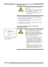
Set the direction of rotation according to the arrow on the fan cowl
(see
and the motor operating instructions).
5. Connect the thermal overload fuse (thermal switch, PTC thermistor
sensor) (see operating and installation instructions for the motor).
6. Close the terminal box cover again.
6.3 Pneumatic connection
CAUTION
Personal injury or property damage through
ejected plugs
If not removed, the plugs on the pressure side of
the pump can be ejected during operation by the
resulting overpressure.
à
Remove the plugs during installation.
à
Wear appropriate personal protective equip-
ment.
Connected components
à
Only connect components to the pump that are designed for the pneu-
matic data and thermal requirements of the pump. (see Chapter
Pressure relief device
à
Protect the compressors by means of a pressure relief device between
the pressure-side connections of the compressor and the first shut-off
valve.
Pump discharge
à
If the pump is being used as a vacuum pump, safely (relating to the
medium and noise) discharge the possibly hot pump discharge via the
pneumatic outlet of the pump.
Decoupling
à
KNF recommends mechanically decoupling the pump from the pipe
system, e.g., through the use of flexible hoses or pipes. In this way it is
possible to prevent the transfer of possible pump vibrations and noises
to the system.
Summary of Contents for N630.12
Page 65: ...13...
Page 67: ...15 9 Documents provided Circuit diagram...
Page 69: ......
Page 82: ...13...
Page 84: ...15 9 Documents provided Circuit diagram...
Page 87: ......
Page 88: ...KNF worldwide You can find our local KNF partners at www knf com...


