


SECTION 7
HIGH PRESSURE WATER
p. 7-7
80078868
WARNING
!
then repeat start procedure, moving from LOW pressure to HIGH pressure
soon after intensifier starts pumping water (no further need to flush air
from lines).
7.2.3 Hard Seal End Cap HSEC, Sealing Head—Disassembly / Re-assembly
NOTE:
KMT Waterjet recommends removing the HP cylinder/ sealing head/ HSEC AS
AN ASSEMBLY for servicing the plunger HP seals, plunger, hydraulic seals, etc. KMT
Waterjet DOES NOT recommend loosening jackbolts except to service the sealing
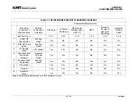
head inlet HP check valve, cone seat, etc. Refer to Table 7.9 for recommended
disassembly / re-assembly practices.
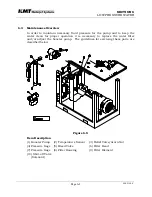
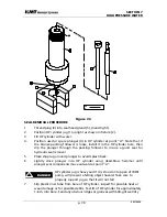
HSEC and Sealing Head Removal
1.
Prior to removing electrical power from the KMT Waterjet pump, extend
plunger at intensifier end to be serviced. Remove connector from proximity
switch on end of hydraulic cylinder closest to HP cylinder jug to be removed.
Start KMT Waterjet pump in LOW pressure mode, allow approximately 20
seconds for appropriate startup and cycling of intensifier to extend and stop
toward the disconnected proximity switch. Shut off KMT Waterjet pump,
shut off LP water supply, and observe LOCK-OUT/ TAG-OUT safety rules.
Before performing maintenance on the waterjet pump
observe electrical LOCK OUT/TAG OUT procedures.
2.
Disconnect HP and LP piping / hoses per paragraph 7.2.1 above.
3.
Loosen jackbolts.
4.
Remove HSEC. Note that sealing head may be removed with end cap.
5.
Remove sealing head. Note that a white plastic spacer ring used to position
the sealing head relative to the HP cylinder bore may remain in cylinder
bore. This ring should be removed prior to re-installing a sealing head to
avoid pushing the ring further into the HP cylinder bore. Note that a fully-
assembled spare sealing head greatly reduces pump downtime, especially
during unplanned maintenance
.
Re-Assemble Sealing Head and HSEC to HP Cylinder
NOTE:
7/16 jackbolts should be coated with molygrease (see Table 7-6) to assure
reliable torque/preload
1.
Verify that sealing head cone surface is smooth. Perform any necessary
maintenance on inlet check valve. (Refer to paragraph 7.3.2) Verify that a
white plastic spacer ring is installed on the ‘nose’ of the sealing head. Verify
O-rings (2 ea) properly installed in ID grooves of HSEC. Check HP cylinder
bore to verify presence of plastic tubular cylinder liner and to verify that no
white plastic spacer ring remains in end of HP cylinder bore. Feel sealing
edge of HP cylinder bore to verify that no unusual blemishes are present
that might hinder proper cone ring seal.
2.
Position plastic spacer ring on seal head. Position sealing head in end of HP
cylinder. Slide HSEC over sealing head.
3.
Back out jackbolts until HSEC makes contact with sealing head. Fully engage
threads of HSEC with HP cylinder. Note that 45 degree cone seal on sealing
Summary of Contents for SL-IV 100D
Page 54: ...SECTION 4 MAINTENANCE Page 4 9 49831902 ...
Page 138: ...SECTION 12 PARTS LISTS May 2003 page 12 5 80079064 ...
Page 140: ...SECTION 12 PARTS LISTS May 2003 page 12 7 80079064 ...
Page 142: ...SECTION 12 PARTS LISTS May 2003 page 12 9 80079064 ...
Page 144: ...SECTION 12 PARTS LISTS May 2003 page 12 11 80079064 ...
Page 146: ...SECTION 12 PARTS LISTS May 2003 page 12 13 80079064 ...
Page 148: ...SECTION 12 PARTS LISTS May 2003 page 12 15 80079064 ...
Page 150: ...SECTION 12 PARTS LISTS May 2003 page 12 17 80079064 ...
Page 152: ...SECTION 12 PARTS LISTS May 2003 page 12 19 80079064 ...
Page 154: ...SECTION 12 PARTS LISTS May 2003 page 12 21 80079064 ...
Page 156: ...SECTION 12 PARTS LISTS May 2003 page 12 23 80079064 ...
Page 158: ...SECTION 12 PARTS LISTS May 2003 page 12 25 80079064 ...
Page 160: ...SECTION 12 PARTS LISTS May 2003 page 12 27 80079064 ...
Page 162: ...SECTION 12 PARTS LISTS May 2003 page 12 29 80079064 ...
Page 164: ...SECTION 12 PARTS LISTS May 2003 page 12 31 80079064 ...
Page 166: ...SECTION 12 PARTS LISTS May 2003 page 12 33 80079064 ...
Page 168: ...SECTION 12 PARTS LISTS May 2003 page 12 35 80079064 ...
Page 170: ...SECTION 12 PARTS LISTS May 2003 page 12 37 80079064 ...
Page 172: ...SECTION 12 PARTS LISTS May 2003 page 12 39 80079064 ...
Page 173: ......
Page 174: ......
Page 175: ......
Page 176: ......
Page 177: ......
Page 178: ......
Page 179: ......
Page 180: ...Date 7 29 2003 Time 09 51 10 AM Title J cad Release 0514 05148549 DWG ...
Page 181: ...Date 7 29 2003 Time 09 52 27 AM Title J cad Release 0514 05148549 DWG ...
Page 182: ...Date 7 29 2003 Time 10 03 41 AM Title J cad Release 0514 05148549 DWG ...
Page 183: ...Date 7 29 2003 Time 10 04 38 AM Title J cad Release 0514 05148549 DWG ...
Page 184: ...Date 7 29 2003 Time 10 05 30 AM Title J cad Release 0514 05148549 DWG ...
Page 185: ......


