


__________________________________________________________
KMS UEGO CAN controller
Part nr: 01-01-01-0010
8
kms.vankronenburg.nl
EN
—
NL
—
DE
EN
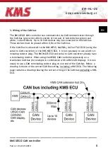
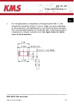
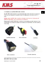
3. Wiring of the CAN bus
The KMS UEGO CAN controller can communicate via CAN communication through
the CAN bus (grey wire) which consists of two pair of twisted wires (green and
white, red and black). Up to 10 CAN devices may be connected to the CAN bus.
These devices must be placed within 0,5m of the CAN bus.
If the CAN Bus is connected to the KMS MP25, MA25(M), IA23 or FA23 ECU (using the
serial to CAN converter) or the KMS MD35 ECU, it is not necessary to use a CAN ter-
minating resistor plug. The KMS MD35 ECU and serial to CAN converter already have
a terminating resistor. When using the UEGO CAN controller separately on a
standalone CAN bus (for example in combination with a KMS CAN display), it is nec-
essary to use a CAN terminating resistor plug on one end of the CAN bus. Below, a
drawing is shown of the correct CAN Bus wiring,
including
a KMS ECU. The following
page contains a drawing showing the correct wiring of the CAN bus
excluding
a KMS
ECU.
Summary of Contents for UEGO CAN
Page 2: ......


