wT 2860/02
Page 24
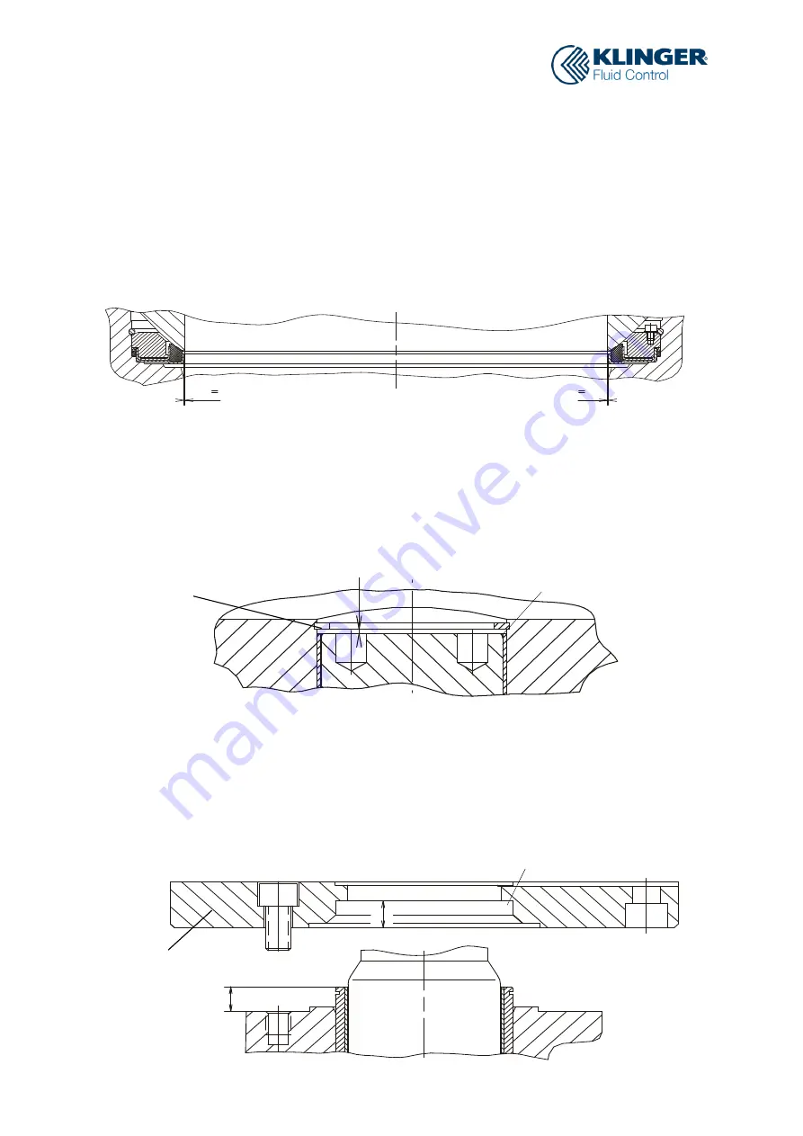
Fig. 15
12.2.4
Inspection of Axial Orientation of the Ball
In the event that the ball is not correctly aligned in terms of its axial orientation or displays
a too large axial freedom of movement, (DN 200 – 400 max. 0.3 mm; DN 500 – 1000
max. 0.5 mm), then discs on the trunnion a) and cushion joints on the top flange b) have
to be used to ensure placement in the center of the body.
The orientation is carried out in the OPEN position, either visually or by means of a
measurement device, from the bore of the ball to the sealing element.
a)
Discs (Pos. 12) on the trunnion
»
The space between the trunnion and the lower edge of the circlip determines the
number and height of the discs
»
Insert discs
»
Insert circlip (Pos. 29)
»
Push the ball, as far as possible, in the direction of the trunnion
b)
Cushion joints (Pos. 16) on the top flange
»
Comparison of measurements: Projection of the bush insert over the body vs.
groove depth of bush insert on flange
»
The measurement difference minus 0.3 or 0.5 (required axial freedom) provides
the number and height of to be inserted cushion joints
»
Assembly of the top flange (Pos.7)
Fig. 16
29
Fig. 17
7
12
16


