


Operating instructions Type INTEC / KH2F-CI
page
5
of
7
Valid from 01/2018
5.1.3
Ball valves with welded ends
The ball valves are suitable for gas welding process and arc welding. The tightness can only be guaran-
teed when the welding is carried out professionally.
Extended welded ends
The face to face dimension has been selected in that way that by professional welding the complete valve
can be welded. The following points must be taken into consideration:
•
Installing the ball valves with at least 3 welding spots (staggered by 120°) into the pipe.
•
Welding process – colour changing pencils are recommended. The temperature during
preheating and welding process must not be exceed 200°C in the area of the body edge.
A cooling during the welding is useful.
•
After the weld seam is cooled down, the body screwing must be tightened with the defined
torque (see Assembly and Repair Instruction).
•
Functional testing.
Short welding ends
•
Installing the ball valves with at least 3 welding spots per connection (staggered by 120°)
into the pipe
•
Dismantling the ball valve and mounting a spacer block instead of it.
•
Connections must be welded completely and cooled down.
•
Remove spacer block and assemble the ball valve, please take the defined torque of the
body connecting bolt into account (see Assembly and Repair Instruction).
•
The original construction seats and body seals can be reused after welding. Please pre-
check for damage.
•
Functional testing.
5.2
Valves with actuators
5.2.1
General notes
The connection of electrical cable may only be carried out by trained staff. The regulations
according to VDE 0100 and VDE 0165 (explosion proofness) must be taken into consideration.
All electrical equipment like actuator, switch box, solenoid valve, limit switches etc. must be
installed safe against flooding in dry rooms. Voltage and frequency must correspond to the details on the
name plate. Should the user want to fit a self automation, the mechanic stopper of the valves must be
removed.
5.2.2
Functional testing
The turning off function must be tested by repeated operation. The regulating distance (mechanical stop-
per) and regulating power (torque limiting) must be adjusted at valves with electrical and pneumatic
actuators. The operating manual of the manufacturer of actuators shall be noticed here.
6 Operation
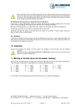
Opening as well as closing is carried out by a turning of the hand lever or the stem by 90°. The valve
closes with a turning to the right side (clockwise). The ball valve is open if the hand lever is in parallel to
the pipe. If the hand lever will be removed, the double “D” shows the condition. (Ball valve is open when
the double “D” is in parallel to the pipe) Ball valves are not applicable to control the volume flow. The
operation of the hand lever should be carried out very slowly.
Using a highly expanded medium due to changes in the temperature, a relief from pressure
must be carried out. Please take also the corresponding instructions into account. If you make
a bore for relief from pressure, the ball valve can only be used in one flow direction.


