


5
GAS CONNECTION
Should conform to gas utility regulations e.g. AS5601 Gas
installations; also refer to rangehood manufacturers
recommendations.
Check gas pressure, note the correct setting from the data plate
sealed inside the front appliance drawer .
This appliance from the factory suitable for NATURAL gas but, if
necessary, can be adjusted for U-LPG by authorised person.
*
Before Leaving
- Check all connections for gas leaks with soap
and water. DO NOT use a naked flame for detecting leaks. Ignite
all burners to ensure correct operation of gas valves, burners and
ignition. Turn gas taps to low flame position and observe stability
of the flame.
When satisfied with the cooker, please instruct the user on the
correct method of operation.
In case the appliance fails to operate correctly after all checks
have been carried out, refer to the authorised service provider in
your area.
GAS CONVERSION AND ADJUSTMENT
When used with natural gas all burners have been preset at our
factory and further adjustment should not be necessary. Conversion
kits to other gases are available from the place of purchase. Do
not attempt to fit the conversion kit yourself. Conversion to U-LPG
gas should only be carried out by an authorized technician.
the characteristics of the gas and electricity output.
The appliance is generally preset for natural gas (so no other
adjustment is necessary) ensure regulator is fitted for N.G.
Ensure that all foreign matter has been cleared from the gas
supply line and also purge all air from the gas system. Connect
to regulator, tighten and check the installation to ensure no gas
leaks occur.
accordance with the manufacturers installation instructions,
relevant local fitting regulations, municipal building regulations,
and 695mm from the floor (depends on adjustment of feet).
The appliance shall be installed by an authorized person in
For the adjustments to U-LPG please operate as specified in the
paragraph GAS CONVERSION AND ADJUSTMENT (pag 4).
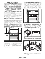
The Gas Connection is male 1/2" BSP and is situated at the right
hand rear of the appliance, approximately 40mm from the side
This appliance can be connected with rigid pipe as specified in
AS5601 table 3.1 or with a
Plumbezy Flexible hose, AGA
Approval number 6196, 10mm
ID, class D and between 1-1.2m
long in accordance with AS5601
for a 'high level connection'.
Ensure that the chain prevents
stress on the hose assembly
when the cooker is moved out
of its normal operating position.
TO FIX THE COOKER TO THE REAR WALL
WARNING -
For safety reasons and to prevent tipping of the appliance,
these stabilizing means must be installed.
The cooker is equipped with 2 chains fixed on each side at the rear of
the cooker near the top (see Fig. A). The chains are fitted with spring
clips which must be clipped to the screw eyes provided with the cooker.
Install the screw eyes as follows :
1.
Drill four 6mm holes (position 1 - 2 - 3 - 4) in the wall
as in Fig. A.
2.
Insert part
R
into the holes then screw in the screw eyes part
G
see Fig. B.
Note: If the part provided is not suitable for the wall material please
use an appropriate device to ensure secure holding of the screw
eyes to the wall.
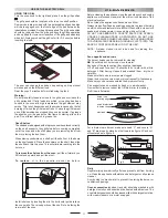
3.
Bring the cooker near the wall and clip the chains on the
screw eyes as in Fig. C.
IMPORTANT: If the cooker is moved for any reason
(e.g. maintenance) resulting in the cooker being unclipped from the
wall, the cooker must be re-clipped to the wall at the completion of
the task.
other relevant statutory code band regulations. If you have some
doubts, please contact the authorities for confirmation concerning
the AS5601 code for gas burning appliances and equipment and
IT IS RECOMMENDED THAT A SERVICE TAP AND UNION BE
FITTED ADJACENT TO THE APPLIANCE INLET TO FACILITATE
FUTURE SERVICING.
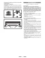
5 burner models: set the burner pressure to 1kPa for Natural Gas
and 2.75kPa for U-LPG with the wok burner operating a full rate.
For commissioning of the appliance with the Oara 97
regulator for Natural Gas, the test point pressure should
be 1.00kPa with all burners operating on HIGH.
Apply a manometer to the test nipple and reset the regulator if
necessary. Do not forget to replace the test nipple screw and to
leave the instructions book with the user.
VERY IMPORTANT FOR THE INSTALLER
Do not attempt to turn or stress threaded elbow of the manifold:
you risk damage to this part of the gas appliance which may void
the manufacturers warranty.
Fig. B
Fig. C
G
wall
wall
Fig. A
76 mm
550 mm
G
R
Hole
55 mm
chain
Position
1
Position
2
55 mm
Position
3
Position
4


