background image

  Service Manual

  Model No.: 

Part

Name

Description

Phenomena

Failure cause

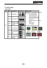
P a n e l   o r 
Polarlzer

Dot Defect

Bright dot dark dot in 
pannel

I n c o m i n g   I n s p e c t i o n 
Standard

Polarizer Bubble

Bladder in Polarizer

Bladder between Polarizer 
and top glass

Polarizer Scratch

Polarizer Scratch

Tine or rigidity arose

F / M   i n s i d e 
Polarizer

E y e w i n k e r   i n s i d e 
Polarizer

Eyewinker inside Polarizer

Circuit

Abnormal Display Abnormal Display

1.Chip lose action
2.IC ahort or jointiog bad
3.Pannel and vsc connect 
bad

Flashing

B r i g h t   a n d   d a r k 
display alternately

- 36 -

Summary of Contents for 55UK30S

Page 1: ...ngs or cautions to advise non technical individuals of potential dangers in attempting to service a product Products powered by electricity should be serviced or repaired only by experienced professional technicians Any attempt to service or repair the product or products dealt with in this service information by anyone else could result in serious injury or death WARNING 55UK30S Model No ...

Page 2: ...and Assemble 4 1 Remove the Stand Base 6 7 7 7 11 11 4 2 Remove the Back Cover 11 4 3 Remove the Adhesive Tape 11 4 4 Remove the Main Board 12 4 5 Remove the Speaker 12 4 6 Remove the Remote Control Board 13 5 Installation Instructions 14 5 1 External Equipment Connections 14 6 Electrical Parts 15 6 2 Circuit Diagram 6 3 Wiring Connection Diagram 16 25 3 3 LED Panel 9 6 1 Block Diagram 15 7 3 4 Co...

Page 3: ...ngerous to make any king of contact with any inside part of this product This symbol indicates that there are important operating and maintenance instructions in the literture accompanying the appliance 1 3 2 Be careful to the electrical shock to rain or excessive moisture This TV must not be exposed to dripping or splashing water 1 3 3 Electro static discharge ESD Some semiconductor solid state d...

Page 4: ...ks with which receivers covered by this service manual might be equipped CAUTION eiver 3 Do not spray chemicals on or near this receiver or any of its assemblies 4 Unless specified otherwise in this service manual clean electrical contacts only by applying the following mixture to the contacts with a pipe cleaner cotton tipped stick or comparable non abrasive applicator 10 by volume Acetone and 90...

Page 5: ...ces Some semiconductor solid state devices can be damaged easily by static electricity Such components commonly are called Electrostatically Sensitive ES Devices Examples of typical ES devices are integrated circuits and some field effect transistors and semiconductor chip components The following techniques should be used to help reduce the ncidence of component damage caused by static by static ...

Page 6: ...elow Note A note provides information that is not indispensable but may nevertheless be valuable to the reader such as tips and tricks Caution A caution is used when there is danger that the reader through incorrect manipulation may damage equipment loose data get an unexpected result or has to restart part of a procedure Warning A warning is used when there is danger of personal injury Reference ...

Page 7: ... Time ms GRAY TO GRAY Angel of View Color Display 16 7M No of Preset Channels OSD Language En Color System PAL SECAM Audio System DK BG I Audio Output Power Built in W 10W 2 Audio Output Power outer W No Total Power Input W 198W Voltage Range V Power Frequency Hz 50 60Hz AC 100 240V 500 DTV 100 ATV 160 150 20 glish Russian ...

Page 8: ... 07 Service Manual Model No 3 Location of Controls and Components 3 1 Board Location No Description A Board Power board 3 2 Main Board B Board Main board ...

Page 9: ... Process signal which incept from exterior equipment then translate into signal that panel can display Main board connector Pin number Signal name Description 1 RSPK RSPK 2 RSPK RSPK 3 LSPK LSPK 4 LSPK LSPK Keypad and remote connector CN201 9 Speaker connector CN601 ...

Page 10: ...3 3 LED Panel 09 Service Manual Model No ...

Page 11: ...Service Manual Model No 10 3 4 Connector Definition 3 4 Connector Definition ...

Page 12: ...4 Disassemble and assemble Remove the adhesive tape indicated on the faces upward 4 2 Remove the Back Cover unit Service Manual Model No 11 4 1 Remove the Stand Base 4 3 Remove the adhesive tape ...

Page 13: ...4 4 Remove the Main board Service Manual Model No 12 4 5 Remove the speaker Take out the speaker ...

Page 14: ...4 6 Remove the remote control board take out the remote controlboard Service Manual Model No 13 ...

Page 15: ...5 Installation Instructions 5 1 External Equipment Connections Service Manual Model No 14 Accessories Remote control refers to user manual Remote control refers to user manual ...

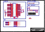
Page 16: ...0A U104 5V 3 SDA 4 EN 1 FB 2 PVDD 8 BST 7 SCL 5 LX 6 PowerPAD 9 EC105 220uF 16V 1 2 RD40 1K R114 NC C78 10uF C103 220pF RD141 220K R41 22K 1 C358 0 1uF C110 0 1uF C76 10uF C130 10uF 6 3V CC0603 L102 3 3uH 8A 1 2 C85 NC 0 1uF R109 NC 150K 1 CD92 0 1uF R111 NC 220K 1 C225 22PF 50V NPO C19 NC 10uF 6 3V R124 15K 1 C88 10uF H3 FOR 侧端子螺丝 1 1 2 2 C128 10uF 6 3V CC0603 C84 10uF C75 0 1uF C122 10uF 6 3V CC...

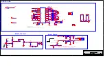
Page 17: ...VDDC G8 VDDC L7 AVDD3P3_ADC V7 AVDD_DDR_VBP_A_DM M13 VDDC_CPU V19 VDDC_CPU V20 VDDC_CPU V18 VDDC_CPU W20 AVDD_EAR33 U9 AVDD_LPLL AA13 AVDD15_MOD K15 AVDD_PLL_B Y14 AVDD_DDR_A M15 AVDD15_MOD K16 AVDD_DDR_VBP_A J27 AVDD_LPLL AB13 VDDP AB15 AVDD3P3_USB T7 AVDD3P3_ADC V8 AVDD3P3_MHL3 AA12 AVDD3P3_MHL3 AB12 DVDD_DDR N9 AVDD_DDR_B K12 AVDDL_MOD T13 AVDDL_MOD AH23 VDDC_CPU W18 VDDC_CPU W19 PADA_EMMC_CTRL...

Page 18: ...DQ6 D_DDR3_DQ5 D DDR3 DQ5 D_DDR3_DQ8 D DDR3 DQ8 D DDR3 DQ24 D_DDR3_DQ24 D DDR3 DQ17 D_DDR3_DQ17 D_DDR3_DQ7 D DDR3 DQ7 D_DDR3_DM1 D DDR3 DM1 D_DDR3_DQ29 D DDR3 DQ29 D DDR3 ODT T2 D_DDR3_ODT D_DDR3_DM2 D DDR3 DM2 D DDR3 DQS2B D_DDR3_DQS2B D DDR3 DQS2 D_DDR3_DQS2 D_DDR3_DQS1B D DDR3 DQS1B D_DDR3_DQS1 D DDR3 DQS1 D DDR3 BA0 T2 D_DDR3_BA0 D DDR3 BA0 T1 D_DDR3_BA0 D CSB2 D_DDR3_DQ31 D DDR3 DQ31 AVDD_DDR...

Page 19: ...TGPIO3 AE4 IFAGC_T AC1 IM_T AC3 SIFM AD2 SIFP AD1 IP_T AC2 TS1DATA_ 0 U23 TS1CLK R23 TS1SYNC T24 TS1VALID P24 PCMDATA 6 CI_DATA 6 AD24 PCMIORD CI_RD AG21 PCMDATA 7 CI_DATA 7 AD23 PCMIOWR CI_WR AC17 PCMDATA 2 CI_DATA 2 AB25 PCMADR 1 CI_A 1 AE23 PCMADR 2 CI_A 2 AC22 PCMADR 10 CI_A 10 SDIO_D2 AD20 PCMADR 12 CI_A 12 AD18 PCMADR 6 CI_A 6 AD21 PCMADR 13 CI_A 13 AE18 PCMDATA 3 CI_DATA 3 AD25 PCMIRQA CI_I...

Page 20: ... REZ 2 NAND CEZ 2 Title Size Document Number Rev Date Sheet of eMMC NAND SD Card V1 0 MSD6A538 6586 Custom 5 14 Saturday February 25 2017 Title Size Document Number Rev Date Sheet of eMMC NAND SD Card V1 0 MSD6A538 6586 Custom 5 14 Saturday February 25 2017 Title Size Document Number Rev Date Sheet of eMMC NAND SD Card V1 0 MSD6A538 6586 Custom 5 14 Saturday February 25 2017 R527 0R NC L501 0R NC ...

Page 21: ...RD62 270K C470 0 1uF R439 10K RD57 NC 0R U9 NC SI 9435 SO8 S1 1 S2 2 S3 3 G 4 D1 5 D2 6 D3 7 D4 8 7 5 3 1 8 6 4 2 RP454 NC 0RX4 R436 10K CN22 NC FIRE 51MR 0 5 SLK NC 41 3D_EN 40 3D_SYNC_O 39 3D_SYNC_I 38 GND 37 RX7P 36 RX7N 35 GND 34 RX6P 33 RX6N 32 GND 31 RX5P 30 RX5N 29 GND 28 RX4P 27 RX4N 26 GND 25 LOCKN 24 HTPDN 23 GND 22 NC 51 NC 50 NC 49 NC 48 NC 47 NC 46 NC 45 NC 44 NC 43 NC 42 RX3P 21 RX3N...

Page 22: ...er Rev Date Sheet of Video VGA Net V1 0 MSD6A538 6586 Custom 7 13 Saturday February 25 2017 Title Size Document Number Rev Date Sheet of Video VGA Net V1 0 MSD6A538 6586 Custom 7 13 Saturday February 25 2017 L20 FB_11_OHM_500MA CD63 1nF JX2 RJ45 TD 1 TD 2 RD 3 TDCT 4 RDCT 5 RD 6 NC 7 CH_GND 8 GND 11 GND 12 NC 10 NC 9 GNC 13 GND 14 R50 NC 10R 0402 J7 AV端子 AV3 绿蓝红 立式 孔距14mm 无孔 无屏蔽 1 1 2 2 3 3 4 4 5 ...

Page 23: ...CLKP 2 HDMI2 CLKN 2 HDMI2 RX0P 2 HDMI2 Detect 2 HDMI3 SCL 2 HDMI3 SDA 2 HDMI3 HPD 2 HDMI3 RX0N 2 HDMI3 RX1P 2 HDMI3 RX1N 2 HDMI3 RX2P 2 HDMI3 RX2N 2 HDMI3 CLKP 2 HDMI3 CLKN 2 HDMI3 RX0P 2 HDMI3 Detect 2 HDMI1 Detect 2 HDMI1 RX0N 2 HDMI1 RX1P 2 HDMI1 RX1N 2 HDMI1 RX2P 2 HDMI1 RX2N 2 HDMI1 CLKP 2 HDMI1 CLKN 2 HDMI1 RX0P 2 HDMI1 SCL 2 HDMI1 SDA 2 HDMI1 HPD 2 UART RX 2 UART TX 2 HDMI ARC 2 HDMI CEC 2 ...

Page 24: ... February 25 2017 Title Size Document Number Rev Date Sheet of Tuner Ext Demod V1 0 MSD6A538 6586 Custom 9 13 Saturday February 25 2017 Title Size Document Number Rev Date Sheet of Tuner Ext Demod V1 0 MSD6A538 6586 Custom 9 13 Saturday February 25 2017 C256 104 1 2 CT8 120pF L511 220 2A 0603 LT7 GZ1005D102CTF C181 NC 1 2 RT4 NC R21 100R RT2 330R RT5 1K8 J4 3P 1 2 3 CT31 NC 56pF TY1 27M L28 0 5PF ...

Page 25: ...ze Document Number Rev Date Sheet of USB Wifi V1 0 MSD6A538 6586 Custom 10 13 Saturday February 25 2017 Title Size Document Number Rev Date Sheet of USB Wifi V1 0 MSD6A538 6586 Custom 10 13 Saturday February 25 2017 C603 0 1uF C617 0 1uF R620 10K P1001 USB2 0X2 W USB1_5V 1 USB1_D 2 USB1_D 3 GND 4 USB2_5V 5 GND 8 USB2_D 6 USB2_D 7 GND 12 GND 11 GND 10 GND 9 DD7 NC 10 4A 0603 R619 100K Q618 AO3407 C...

Page 26: ..._N 2 TS_MOCLK 2 PCM_OE_N 2 PCM_WE_N 2 TS_MOSYNC 2 TS_MOVLD 2 PCM_CD_N 2 PCM_IORD_N 2 TS_MDO 7 0 2 TS_D 7 0 2 TS_VLD 2 TS_CLK 2 TS_SYNC 2 Title Size Document Number Rev Date Sheet of PCMCIA CA V1 0 MSD6A538 6586 A4 11 14 Saturday February 25 2017 Title Size Document Number Rev Date Sheet of PCMCIA CA V1 0 MSD6A538 6586 A4 11 14 Saturday February 25 2017 Title Size Document Number Rev Date Sheet of ...

Page 27: ...0K NC FB6 220R 500mA CD11 220uF 16V CD39 1000PF CD25 1uF 25V X5R 0603 LD7 33uH RD123 4 7K RD10 6 8K NC CD8 220uF 16V CD33 0 22uF 16V X5R CD32 1uF 25V X5R 0603 QD2 3904 3 1 2 LD5 33uH CD37 1000PF C605 1uF 25V X5R 0603 RD11 10K CD27 1uF 25V X5R 0603 CD73 1uF 6 3V X5R UD4 9108 TPA3113D2 SD 1 FAULT 2 LINP 3 LINN 4 AGND 8 AVCC 7 GAIN1 6 GAIN0 5 GVDD 9 PLIMIT 10 RINN 11 RINP 12 BSPR 17 OUTPR 18 PGND 19 ...

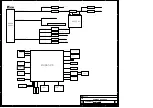
Page 28: ...5A MSD6586 L511 HDMI3 3 3V_TUNER PWR_ON OFF 5V_wifi 0 2A USB2 0X2 W USB3 0 0 9A SPEAKER USB输入X2 USB2 0 LNB IN AMP AV输入X1 AV U9 1 05_VDDC_CPU 3A MSH6110A RT5047 U5 18V 13V 500mA 1 5V_DDR 1 5A U17 SY8113 TL1 220Ω 2A 0603 5V 0 56A 3 3V_TU 5V 0 2A 5V 0 67A 12V 1 5A 12V 0 94A 12V 1 65A 5V 2A 12V 0 56A 12V 0 33A ARC WIFI YPbPr输入X1 Title Size Document Number Rev Date Sheet of Audio AMP V1 0 MSD6A538 6586...

Page 29: ...Service Manual Model No 25 ...

Page 30: ...Service Manual Model No 7 Trouble shooting 7 1 Simple check 26 ...

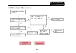
Page 31: ... is 12V at Pin35 in CN202 No Replace the QD6 Yes Check if there is 43V at PCN4 Yes No test if J16 Pin3 3 3V Pin13 normally Change LVDS wire No Replace PU5 Check if PQ6 PD14 PR46 works normally Yes Replace PQ6 PD14 No Service Manual Model No 7 2 Main board failure check 27 12V ...

Page 32: ...ve picture Check if there is sound input signal Check the input source Yes No Check if there is signal at C607 and C605 Check if there is signal at C201 and C206 No Yes Check if there is signal at FB11 FB12 FB13 FB14 Change U204 Check the speakers Yes Change UD4 Check LD3 voltage 12V LD3 Else ...

Page 33: ...o Yes Check L8 1 5 V Check L14 0 97 Check L19 1 06V Change U17 Change U23 Change U104 No Yes Change mainchip U202 No Change Mainboard Still having problems No sound No picture NO LED indicate Check PD15 24V Check PD3 12V Yes No Change Mainboard Service Manual Model No 29 ...

Page 34: ...oor sound Change sound system No Update the software and make the reboot or change the Mainboard Still having problems For ease of use recommend that customer format the picture and sound settings in the automatic option Service Manual Model No 30 ...

Page 35: ...r to relative instructions in the Manual for color adjust No No Yes Yes Check out of picture and sound system of this channel Change the channel to the right sound system PAL M N NTSC M No color for some channel program black and white Still having problems Updata the software and make the reboot or change the maiboard Service Manual Model No 31 ...

Page 36: ...place PD3 How to know whether the Power board is broken Still having problems Check if Main board LVDS wire Panel are in good condition No Reconnect the power cord with the outlet or Power board Yes EC805 whether have 300V No F800 or D803 D804 D805 D807 Yes Service Manual Model No 32 ...

Page 37: ...ght software and work well 5 Verify if the Y1 Crystal has the right frequency Panel not work 1 Check the LED Back light set up IC output and input are working 2 Verify if the Mainboard output the right On Off signal to power board 3 Verify if the Mainboard output the LVDS singal to panel T con board 4 Verify if the software is the right version of this model 5 Change the LVDS wire to check if it s...

Page 38: ...ct well Verify the power cord 5V standby is working 3 Check if voltage of the POWER ON OFF of the power board part is on the high level voltage 4 12V 5V output check if there is 12V 5V output on the power board Check if Main board LVDS wire Panel are in good condition 34 ...

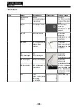
Page 39: ...or cracking Dim or L D TCP Sunken TCP lead cracking ACF bonding short Awful environment and something electric enter into LCD Mis align between TCP and Panel Panel failure TCP failure V Dim Vertal gray line V L D Vertical color line light or dark forever H B D Horizontal bar H Dim Horizontal gary line H L D H o r i z o n t a l line light or dark forever ...

Page 40: ...er Bubble Bladder in Polarizer Bladder between Polarizer and top glass Polarizer Scratch Polarizer Scratch Tine or rigidity arose F M i n s i d e Polarizer Eyewinker inside Polarizer Eyewinker inside Polarizer Circuit Abnormal Display Abnormal Display 1 Chip lose action 2 IC ahort or jointiog bad 3 Pannel and vsc connect bad Flashing B r i g h t a n d d a r k display alternately 36 ...

Page 41: ...display Maybe caused by surge current and EDS Black Screen B L normal only Black screen display FIIcker Crosstalk LCD Vcom imbalance Abnormal Color Only color abormal Capacitance improper bring crosstalk inside LCD pannel Abnormal Color Only color abnormal 1 Chip lose action 2 I C s h o r t o r jointion bad 3 Pannel and vsc connect bad ...

Page 42: ...ss between wire and electrode B L dark B L brightness darker than normal Connect badnessShort between wire and electrode B L wire damaged B L wire damaged Operation abnormal or systemic noise B L wire open Without backlight Operation abnormal or systemic noise B L shut down B L shutdown in sometime Short bitween lamp housing and wire Because consume power too much F M F M inB L white balck Rotundi...

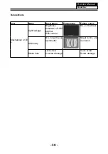
Page 43: ...ription Phenomena Failure cause Mechanlcal or B L Light leakage Brightness at bottom of LCM brighter than normal B L unit badness Uniformity B L brightness asymmetric Sheet in B L unit is uneven Mount hole Lack screw or screw damage Lack screw Screw damage ...

Reviews: