background image

OIL CONDENSING BOILER 

INSTALLATION AND USER MANUAL


INSTALLATION & USER MANUAL                                                                                                                             

www.krb.co.kr


33


3.11.


Boiler commissioning 


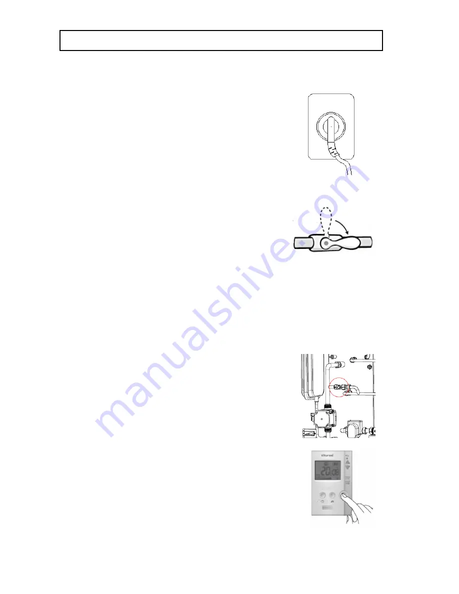
Connect power supply. (AC230V / 50Hz)


Open the fuel line valve to feed fuel. 

(Vent the air in the fuel line first.)


Turn  on  power  by  pressing  the  power  switch  of  the 

controlled inside of the boiler.   
And turn on the power button of the room 

temperature controller. 
If the boiler is not filled with water, 

Error 95 is 

displayed.


Open the feed water valve to replenish water. 

After water refill, 95 

error is released

.   

Close the feed water valve 

when the pressure 

1.5kgf/cm2.


(Feed water pressure must be lower than the max 

allowable operation pressure.)


Set up the room temperature controller to a desired   
temperature. After temperature and reservation 
function setting, the operation lamp turns on or off, 
and the respective functions are executed. 
If  ignition  fails,  press  the  power  button  on  the  room 
temperature controller for a restarting.


Summary of Contents for TURBO CONDENSING - 13

Page 1: ...CONDENSING BOILER INSTALLATION AND USER MANUAL INSTALLATION USER MANUAL www krb co kr 1 Types TURBO CONDENSING 13 TURBO CONDENSING 17 TURBO CONDENSING 21 TURBO CONDENSING OIL BOILER INSTALLATION USER MANUAL ...

Page 2: ...ions and pipeline 16 3 4 Piping 17 3 5 Flue installation 18 3 5 1 General flue installation 18 3 5 2 Installation in the ceiling 19 3 5 3 General cautions for flue installation 20 3 6 Condensate drainage 21 3 6 1 Connecting neutralizer 21 3 6 2 Replenishing water to neutralizer 22 3 7 Fuel line 23 3 7 1 Fuel tank installation 23 3 7 2 Oil filter and fuel line installation 24 3 7 3 Fuel line air ve...

Page 3: ... 37 4 4 Outing leave function 38 4 4 1 Enable leave function 38 4 5 Bath operation 39 4 5 1 Run bath operation 39 4 5 2 Setting up hot bath water temperature 39 5 Product Maintenance 40 5 1 Boiler cleaning 40 5 2 Burner cleaning 41 5 3 Cleaning neutralizer 43 6 Troubleshooting 44 7 Product Disposal 45 8 Technical Data 46 8 1 Basic specification 46 8 2 Specification for combustion 47 8 3 Spare part...

Page 4: ... in operation and abide by the maintenance instructions described in this manual Once again we would like to express our thanks to you Modification of the document The content of this document is subject to change without written prior notice to improve the product It is prohibited by the Intellectual Properties Law to copy or reproduce all or a part of this document without prior written consent ...

Page 5: ...uries or even death or damage to the product Please read the message carefully and observe the instruction This symbol underlines the information important for proper operation of the boiler Failure to comply the instruction can lead to malfunction or deteriorated performance Matters must be observed Other special symbols Caution for electric shock Don t touch No heat source The system must be gro...

Page 6: ...he screen Ultra high efficiency boiler Specially designed Hi Fin structure reduced burner load by about one half and condensing technology provides higher thermal efficiency Automatic control system All the basic functions including At Home Reservation Outing and Bathing modes fault diagnosis anti freezing and circulation pump seizure prevention are automatically controlled Condensate neutralizer ...

Page 7: ...he product The boiler must not be used for any other purpose than the intended purpose Operating the boiler for an unintended purpose may lead to dangerous situation Do not step on the boiler or use the boiler as a support Do not hang out wash near the boiler or flue for drying Wash hangers or similar devices must be kept away from the boiler by an appropriate distance Otherwise fire may break out...

Page 8: ...ied the boiler will not start up and an alarm will be triggered Check that the boiler is filled up with boiler water If the boiler water level is lower than the sensor level the check lamp will be lit and ignition will fail Open at least one of the hot water distributor valves while operating the boiler If all the valves of the distributor are closed during operation the boiler can be damaged or c...

Page 9: ...nsulated in cold regions climate Do not clean the boiler and room temperature controller with wet cloth Otherwise electric shock may occur or internal parts may be deteriorated or failed due to the infiltration of moisture Do not contact the flue tube or pipeline during operation because they are very hot Failure to comply with this can lead to burn of the user Be cautious when opening the hot wat...

Page 10: ...s are inherent characteristics of the materials therefore such minor defects do not form the basis for claim This company does not take any responsibilities for the problems caused by negligence mistake inappropriate maintenance and installation works not in compliance with the instructions specified by this company Please refer to the pertinent descriptions in this manual This company does not ta...

Page 11: ...Sensor Expansion tank 24 Neutralizer support 4 Upper cover 25 Baffle plate 35 Burner gasket 5 Exhaust flue connector 15 16 Circulating pump Pressure gauge 26 Hot water coil 36 Hood packing 6 Side rear casing 27 HI Fin flue pipe 37 Exhaust tube 7 Power switch 17 3Way valve 28 Hot water outlet 38 Flue O ring 8 Bottom casing 18 Upper hood 29 Hot water inlet 39 Condensate drainage 9 Condensate drain h...

Page 12: ...w krb co kr 12 2 2 Burner construction Fig 2 3 Exploded view of burner 1 Burner motor 8 Burner upper casing 2 Burner tube 9 Venturi pipe 3 Burner lower casing 10 Primary fan 4 Secondary fan 11 Flame detector 5 Oil nozzle 12 Fan casing 6 7 Nozzle adapter Ignition rod 13 Air damper ...

Page 13: ...set components Fig 2 5 Accessories 1 Flue adapter 7 Power cord 13 Oil hose bushing 2 Extending tube 500 mm 8 Condensate drain hose 14 User s Manual 3 Exhaust flue 9 Cleaning brush 15 Room temperature controller 4 Extending tube 300 mm 10 Condensate hose clip 16 Flue tube band 5 Elbow 11 Oil hose 6 Finish material 12 Oil filter ...

Page 14: ...the boiler cannot but be installed outdoor provide a shelter and heat insulation for freeze protection Avoid outdoor installation which may cause freezing and or bad combustion due to wind or rainfall Avoid the cold hot air outlet of cooler heater Air intake and exhaust tube flue must be provided for uninterrupted air feed and exhaust The floor under the boiler must be built with incombustible mat...

Page 15: ...er feed water line is connected directly to city water line install a filter pressure regulator valve check valve safety valve and closed type expansion rank in the incoming line The safety valve and closed expansion tank must have sufficient capacities The hot water line pipes must be coated product or stainless steed products The capacity of the circulation pump must be sufficient for the hot wa...

Page 16: ...oduct dimensions and pipeline size Fig 3 2 Boiler dimensions Unit mm Item Size Item Size A 385 5 H 77 5 B 933 5 I Flue dia DN 77 C 650 5 J Hot water outlet G 1 2 D 661 5 K Hot water inlet G 1 2 E 493 5 L Heating return drain G1 F 308 5 M Heating water outlet G1 G 244 5 N Condensate drain hose DN 16 5 ...

Page 17: ...ng system ㆍ Please observe the cautions for piping ㆍ The splitters distributor manipulator must be provided with air vent valves ㆍ The feed water line must be provided with a filter unit to remove metal and other foreign matter in the water ㆍ The hot water line pipes must be coated product or stainless steel products ...

Page 18: ... installation method A Min 15 cm from the ceiling a Boiler flue tube supplied B Min 40 cm from the wall b Incombustible material C Min 40 cm from the wall c Flue tube finish material supplied Fig 3 5 Correct installation of the flue tune Do not install the exhaust end of flue inside the wall The flue tube must be protruded into outdoor sufficiently for smooth exhaustion ...

Page 19: ...N USER MANUAL www krb co kr 19 3 5 2 Installation in the ceiling Fig 3 6 Installation in the ceiling Fig 3 7 Detailed view in the ceiling a Inspection hole d Insulation 20 mm or more thick b Exhaust pipe e Min 50 mm from the ceiling c Cover incombustible material ...

Page 20: ...or other incombustible material whose thickness is at least 20 mm ㆍ The joints of the exhaust stack shall be assembled with O ring in sufficient depth to prevent leak or disconnection ㆍ Seal the joints with heat proof aluminum tape or other flame retardant material certified ㆍ The maximum length of the feed exhaust air tube shall be 5 m or less and 3 or less bends The bend at the end of the exhaus...

Page 21: ...w krb co kr 21 3 6 Condensate drainage 3 6 1 Connecting neutralizer Fig 3 8 Connecting a condensate drain hose Fig 3 9 Disposition of a condensate drain hose 1 Neutralizing agent 4 Condensate drain hose 2 Condensate drain hose clip 5 Drainage PVC or stainless steel 3 Neutralizer ...

Page 22: ...nless steel sewer ㆍ The condensate must be always filled with water from after the first installation Replenish the water whenever necessary Pour slowly about one liter of water into the end of flue for easy water replenishing if not filled with water exhaust gas may enter the boiler which is dangerous ㆍ The condensate water from the boiler system is not potable nor can be used for washing ㆍ If th...

Page 23: ... safety distance of about 2 m from the boiler or construct a fire wall between the boiler and fuel tank ㆍ The fuel tank must be provided with a pressure escape tube and drain valve for safety ㆍ Fuel outlet must be provided with a fuel cut off valve ㆍ Fix the fuel tank on the ground to prevent falling over and horizontal on the ground ㆍ Height of the fuel tank must be within 2 m above and below the...

Page 24: ...filter and fuel line installation Fig 3 12 Oil filter installation A Oil filter supplied with the boiler B Fasten clockwise using an appropriate tool Fig 3 13 Oil hose connection C Oil hose supplied with the boiler D Oil hose bushing Supplied with the boiler E Fuel pipe F Seal the joints to prevent leak ...

Page 25: ... This is applicable only when the fuel tank is higher than the fuel filter unit 3 If the fuel tank is lower than the filter unit air cannot be removed with this method In such case loosen the air vent bolt on the fuel pump and turn on boiler power supply 4 After about 6 7 seconds the fuel pump discharges air with ticking sound The LED lamp on the controller flashes and the boiler stops 5 Turn off ...

Page 26: ...ightening arrestor or fuel pipe Otherwise the product may fail or even exploded ㆍ Boilers must be grounded to prevent electric shock or other accident by leakage current ㆍ For the 230V power supply grounding and cable works observe the applicable laws and regulations ㆍ If the 230V power supply is obtained by individual voltage raise in a 110V region make sure to provide a ground connection In this...

Page 27: ...OIL CONDENSING BOILER INSTALLATION AND USER MANUAL INSTALLATION USER MANUAL www krb co kr 27 3 8 2 Wiring diagram Fig 3 15 Wiring diagram ...

Page 28: ...ctor cable structure Fig 3 16 16 Pin connector Terminal No Classification Color 1 2 3 AC 230V COM White 4 AC 230V Sky Black 5 Burner motor Yellow 6 7 Ignition transformer Red 8 Fuel pump Blue 9 Earth Yellow Green 10 11 12 13 Burner motor COM Yellow 14 15 Ignition transformer COM Red 16 Fuel pump COM Blue ...

Page 29: ...lassification Color 1 Low water level sensor Red 2 DC 12V Red 3 GND Gray 4 GND Blue 5 GND White 6 GND Black 7 DC 12V Yellow 8 Low water level sensor COM Yellow Green 9 Bimetal Thermostat Red 10 Temperature sensor Gray 11 Hot water sensor White 12 Room temperature controller Red 13 Flame detector Yellow 14 Air pressure switch Yellow ...

Page 30: ... MANUAL INSTALLATION USER MANUAL www krb co kr 30 Fig 3 18 8 Pin connector Terminal No Classification Color 1 Circulation pump Yellow 2 3 3Way valve Heating Red 4 3Way valve Hot water Blue 5 Circulation pump COM Green 6 7 3Way valve COM Black 8 ...

Page 31: ... door cold draft direct sunlight within the reach of children A Screws B Hook C Cable hole 2 Connect cable to the terminal block on the backside of the room temperature controller 3 Match the hook of the controller and the ring of the mounting plate pull down the controller while pressing towards the wall Do not lay under the floor or in the same conduit with electric cable Otherwise the signals m...

Page 32: ...terial near the boiler Is the flue correctly installed Was the air in the fuel line removed Was the air in the hot water line removed Are the hot and low water lines separated Is the feed water line correctly installed Are the pipelines and flue properly insulated Is the power supply AC230V 50Hz Is the neutralizer filled up with water Is the fuel valve operation and no fuel leakage All above quest...

Page 33: ...roller If the boiler is not filled with water Error 95 is displayed 4 Open the feed water valve to replenish water After water refill 95 error is released Close the feed water valve when the pressure 1 5kgf cm2 Feed water pressure must be lower than the max allowable operation pressure 5 Set up the room temperature controller to a desired temperature After temperature and reservation function sett...

Page 34: ...n Use this button to select bathing function 7 Down button Used to edit setting values 3 Function button AT Home Reservation Outing function selector button 8 Hot water temperature button Use this button to set up heating water temperature 4 Room temperature sensor Measures room temperature 9 Reservation setting button Use this button for reserved start up and shut down timer setting 5 LED indicat...

Page 35: ...emperature Mode 3 After setting up a desired operating mode press the Function button to finish setting and return to the previous function What is Operating Modes Heating mode can be classified into Room mode and Water Temperature mode Room mode the boiler operates by comparing the current temperature and set up temperature of the room temperature controller Water Temperature mode the boiler oper...

Page 36: ...erature the setting will be entered and effective after about 10 seconds 4 2 3 Water Temperature mode operation 1 Heating water temperature display will flash when the heating water temperature setting key is pressed 2 While the display is flashing set up the heating water temperature at desired level using the UP Down buttons 3 The heating water temperature can be set up between 50 85 at 1 unit D...

Page 37: ...sing the UP Down buttons When the setting is finished at this step the reserved stop time will apply first 2 To change reserved stop time press the Reservation Setting button once again With the Up Down buttons you can adjust the time minutes when the Reserved Stop time flashes When the setting is finished at this step the reserved stop time will apply first 3 To change reserved starting time pres...

Page 38: ... protection function maintains the boiler system floor heating pipeline and connecting lines at appropriate temperature to prevent damage by freezing When you leave home in winter the power of the boiler system must be ON and the fuel supply valve must be open for freeze protection In extremely cold weather set the room temperature at about 10 15 to prevent freezing in a long leave In the situatio...

Page 39: ... the figure 3 Bath water temperature can be set up between 41 85 at 1 unit 4 The setting will be entered and effective after about 10 seconds if without any button input 5 After setting press the Function or Bath button to complete the setting and enter the respective function or Bath function Take care of burn injury when using hot water When using hot water very hot water may come out of the hot...

Page 40: ...off fuel feed Remove the A S cover and front casing 2 First disconnect all the cables from the burner 1 Disconnect copper fuel pipe from the burner nozzle adapter using a tool 2 Remove two fixing nuts on both sides of the burner 3 Remove 6 nuts on the hood and heat exchanger 3 Disconnect the hose from the neutralizer at the bottom of the boiler The hose is joined with a clip 4 Remove the exhaust h...

Page 41: ...mble the boiler in the reverse direction of disassembly 8 Verify that the boiler is assembled correctly ㆍ Soot or foreign matter in the boiler can reduce life span and efficiency of the boiler and can cause fire ㆍ Contact a nearby service center for cleaning by at least once a year ㆍ Cut off power supply before cleaning the boiler Otherwise the user may get electric shock ㆍ Cool down the boiler su...

Page 42: ...oiler in the reverse direction of disassembly ㆍ Soot or other foreign matter on the burner tube and or flame detector may lead to boiler failure ㆍ Contact a nearby service center for cleaning by at least once a year ㆍ Cut off power supply before cleaning the boiler Otherwise the user may get electric shock ㆍ Cool down the boiler sufficiently before cleaning the boiler Failure to comply with this c...

Page 43: ...Remove foreign matter if any in the neutralizer Replace the neutralizing agent at every 3 5 years 4 After cleaning assemble the boiler in the reverse direction of disassembly Refill the neutralizer with water ㆍ Cool down the boiler sufficiently before cleaning the boiler ㆍ Contact a nearby service center for cleaning by at least once a year ㆍ Wear safety gloves when handling the neutralizing agent...

Page 44: ...not run if the setting temperature is lower than the actual room temperature If the boiler has been shut down for a long time the hot water circulation pump may have been seized Try to rotate the shaft with screw driver or other tool If the boiler still fails to heat the room call your nearest dealer or A S center If a figure flashes on the room temperature controller 01 This means flame detection...

Page 45: ...el in the boiler is lower than the low limit Replenish water using the feed water valve as necessary If water replenishment fails to solve the problem check the connection of the low water level sensor and casing ground cable If the problem persists call your nearest dealer or A S center for help 98 When overheat bimetal switch is disconnected If the problem persists call your nearest dealer or A ...

Page 46: ... 83 Maximum heat input kW 15 58 20 97 26 36 Type Floor installation semi closed forced exhaust ON OFF Modulating multi stage On Off Fuel Light Oil Heat transfer area M2 1 26 1 26 1 43 Water volume Liter 28 28 24 2 Heating efficiency Condensing 100 99 98 Normal 94 93 92 Hot water efficiency 94 93 92 Hot water heating type Indirect heating Hot water supply capacity ΔT 25 Liter min 8 3 10 7 13 0 ΔT 4...

Page 47: ...tance and combustion chamber pressure for boilers operating with positive pressure mbar 0 2 0 2 0 2 Water resistance mbar 10K 380 20K 480 8 2 Combustion specifications Item Unit TURBO CONDENSING 13 TURBO CONDENSING 17 TURBO CONDENSING 21 Thermal output condensing kW 13 6 16 6 17 8 21 7 21 9 26 8 Thermal output Normal kW 12 9 15 8 16 7 20 4 20 4 24 9 CO emission rating Class 1 1 1 NOx emission rati...

Page 48: ...NG 21 Controller NCTX 300CE Indoor temperature controller NCTR 50 Burner motor KM 061 E 1 5 Oil nozzle Danfoss 0 4 80 H Danfoss 0 5 80 H Danfoss 0 6 80 H Fuel pump K TAISAN MP35SLR S E P 0 5G 8 5K K TAISAN MP35SLR S E P 0 5G 10K Flame detector RS 500 Temperature sensor SD 450 Low level sensor WL 100 Ignition transformer EI 2P C30 Inner circulation pump GRUNDFOS UPM3 FLEX AS 15 70 130 AZJ ...

Page 49: ...LLATION USER MANUAL www krb co kr 49 8 4 Standard resistance of temperature sensors The actual water temperature and the water temperature display on the room temperature controller can be compared by measuring the resistance of the water temperature sensor ...

Page 50: ...NUAL www krb co kr 50 8 5 Time chart Fig 8 1 Time chart for initial operation Fig 8 2 Time chart in loss of flame during operation Burner motor Ignition Trans Fuel pump Flame detectort Time s 6s 7s 7s Burner motor Ignition trans Fuel pmp Flame detector 시간 초 11s 1s 6s 7s 7s ...

Page 51: ... 1 s Time interval for ignition transdormer to operate before fuel injection to help ignition POST IGNITION TIME 7 1 s Time interval for ignition transformer to operate after ignition to prevent ignition falire caused by incomplete combustion and ensure stable combustion POST PURGE TIME 11 1 s Time for purging waste gas in the combustion chamber after burner off for safety BURNER SHUTDOWN TIME 1 s...

Page 52: ...OIL CONDENSING BOILER INSTALLATION AND USER MANUAL INSTALLATION USER MANUAL www krb co kr 52 8 6 Burner fan motor performance curve Fig 8 3 Burner motor performance curve ...

Page 53: ...r 53 www krb co kr The content of this manual may be subject to correction without prior notice for purposes of improving the appearance and capabilities of the product This company shall not assume responsibility for any accident caused by the user s arbitrary modification of the product ...

Reviews: