


9
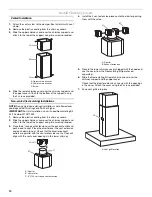
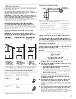
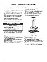
3. Attach the extension to the support using the 4 bolts supplied
with the extension kit. Tighten bolts securely.
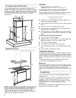
Complete Chimney Support Installation
1. Remove wiring box cover located on the top section of the
chimney support.
2. Install a UL or CSA listed strain relief in the wiring box so that
the screws can be tightened after the chimney support is
attached to the ceiling.
3. Lift chimney support into its final location, feeding electrical
wire through the strain relief.
4. Position the chimney support so that the large end of the
keyhole slots are over the ceiling attachment bolts. Then
push the chimney support so that the bolts are in the neck of
the slots. Tighten bolts securely.
IMPORTANT: The chimney support must be securely
attached to the ceiling.
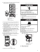
5. Determine the desired length of the chimney support.
6. Remove the four screws and adjust the length of the lower
chimney support as needed.
NOTE: This is the only section that can be adjusted.
7. Replace the four screws and tighten securely.
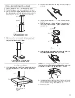
Electrical Connection
1. Disconnect power.
2. Use UL listed wire connectors and connect black wires
together.
3. Use UL listed wire connectors and connect white wires
together.
4. Connect ground wire to the green ground screw inside the
range hood terminal box.
5. Tighten strain relief screw.
6. Install terminal box cover.
A. Chimney extension frame
B. Chimney support
C. Bolt
D. Captive threaded insert
A. Screws
B
A
D
C
A
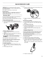
A. Ground screw connector
B. Green wire
C. Power supply cable
WARNING
Electrical Shock Hazard
Disconnect power before servicing.
Replace all parts and panels before operating.
Failure to do so can result in death or electrical shock.
WARNING
Fire Hazard
Electrically ground the blower.
Use copper wire.
Connect ground wire to green ground screw in
terminal box.
Failure to do so can result in death, fire, or
electrical shock.
C
A
B
Summary of Contents for W10268947B
Page 14: ...14 WIRINGDIAGRAM ...