TECHNICAL EDUCATION
JOB AID 4317410
KAC-46
27˝ & 30˝ ELECTRIC
BUILT-IN MICROWAVE/OVEN
COMBINATION
MODELS: KEMS378S & KEMS308S
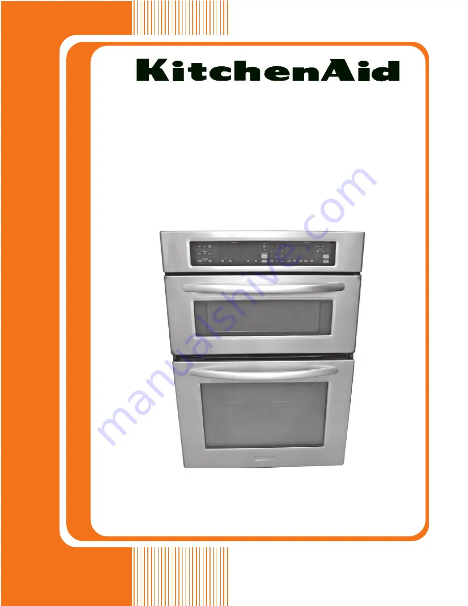
Page 1: ...TECHNICAL EDUCATION JOB AID 4317410 KAC 46 27 30 ELECTRIC BUILT IN MICROWAVE OVEN COMBINATION MODELS KEMS378S KEMS308S ...
Page 2: ...he oven The Wiring Diagram and Strip Circuits used in this Job Aid are typical and should be used for training purposes only Always use the Wiring Diagram supplied with the product when servicing the oven GOALS AND OBJECTIVES The goal of this Job Aid is to provide information that will enable the In Home Service Professional to properly diagnose malfunctions and repair the 27 30 Electric Built In ...
Page 3: ...ght 4 7 Removing The Magnetron Thermostat And The Magnetron 4 9 Removing The Main L1 Filter Main L2 Filter And Grill Thermostat 4 11 Removing The Magnetron Fan Motor The Inverter 4 13 Removing The Convection Thermistor And Grill Element 4 16 Removing The Lower Oven Appliance Manager 4 18 Removing The Line Fuse Holder Lower Oven Light Transformer 4 20 Removing The AC Terminal Block 4 21 Removing Th...
Page 4: ...able Motor 5 9 Measure Oven Input Current 5 9 LOWER OVEN COMPONENTS 5 10 Door Latch Assembly 5 10 Broil Element 5 11 Oven Temperature Sensor 5 11 Convection Ring Element 5 12 Convection Fan Motor 5 12 Meat Probe Jack 5 13 Blower Motor 5 13 Blower Speed Resistor 5 14 Oven Shutdown Thermal Cutoff TCO 5 14 Hidden Bake Element 5 15 DIAGNOSTICS TROUBLESHOOTING 6 1 Diagnostics 6 1 Failure Error Display ...
Page 5: ... can kill or hurt you and others All safety messages will follow the safety alert symbol and either the word DANGER or WARNING These words mean All safety messages will tell you what the potential hazard is tell you how to reduce the chance of injury and tell you what can happen if the instructions are not followed You can be killed or seriously injured if you don t immediately follow instructions...
Page 6: ...pping or Abuse c Before turning on microwave power for any service test or inspection within the microwave generating compartments check the magnetron waveguide or transmission line and cavity for proper alignment integrity and connections d Any defective or misadjusted components in the interlock monitor door seal and microwave generation and transmission systems shall be repaired replaced or adj...
Page 7: ... POSITION 2ND POSITION 1 SINGLE OVEN 4 24 WIDE 2 DOUBLE OVEN 6 36 WIDE 3 COMBO OVEN 7 27 WIDE 5 MINI OVEN 0 30 WIDE 6 COMBO W MINI OVEN FEATURE CODE 0 STANDARD FEATURES 1 STANDARD FEATURES ELEC COOK 2 INDOOR OUTDOOR FEATURES 5 DELUXE FEATURES 6 DELUXE FEATURES ELEC CLOCK 7 DELUXE FEATURES THERMAL CONVECTION 8 DOUBLE THERMAL CONVECTION 9 MULTI MODE YEAR OF INTRODUCTION S 2006 COLOR CODE BL BLACK SS...
Page 8: ...1 4 MODEL SERIAL NUMBER LABEL AND TECH SHEET LOCATIONS The Model Serial Number label and Tech Sheet locations are shown below Model Serial Number Label Location Tech Sheet Location Under Top Cover ...
Page 9: ...asure or Min Max 41 1 4 41 1 4 Cutout Width Measure or Min Max 25 1 2 28 1 2 Cutout Depth Measure or Min Max 23 1 4 23 1 4 Other Dimensions Conduit Size Length Diameter 57 1 2 57 1 2 Ratings Electric Voltage Phase Frequency Hz 208V 240V 2 3 60 208V 240V 2 3 60 Total Connected Load in kW 240 Volts 11 35 11 21 208 Volts 9 24 9 10 240 120V AC 11 42 11 42 Circuit Amps 40 40 Upper Microwave Oven Distri...
Page 10: ...00 Watt Accessories Baking Rack Yes Yes Convection Grid Yes Yes Broiler Pan Grid Part Comment 8303973BU 4457277 8303973BU 4457277 Roasting Rack Part Comment 3181534 3181534 Teflon Coated Crisp Pan Kit Yes Yes Steam Vessel Yes Yes Miscellaneous Product Literature Installation Instructions Part 8304337 8304377 Service Manual Part 4317410 4317410 Tech Sheet Part 8304098 E 8304417 F 8304098 E 8304417 F...
Page 11: ...overning codes and ordinances Cabinet opening dimensions that are shown must be used Given dimensions provide minimum clearance with oven Recessed installation area must provide complete enclosure around the recessed portion of the oven Grounded electrical supply is required See Electrical Requirements page 2 2 Electrical supply junction box should be located 3 7 6 cm maximum below the support sur...
Page 12: ...es It is not recommended to ground to a gas pipe Check with a qualified electrical installer if you are not sure the oven is properly grounded It is not recommended to have a fuse in the neutral or ground circuit This oven must be connected to a grounded metal permanent wiring system Be sure that the electrical connection and wire size are adequate and in conformance with the National Electrical Co...
Page 13: ...rom the oven should be con nected directly to the junction box Fuse both sides of the line Do not cut the conduit The length of conduit provided is for serviceability of the oven A UL listed or CSA approved conduit con nector must be provided If the house has aluminum wiring follow the procedure below 1 Connect a section of solid copper wire to the pigtail leads 2 Connectthealuminumwiringtotheadde...
Page 14: ...erials and tape from the oven 4 Removethehardwarepackagefrominside the bag containing literature 5 Remove and set aside racks and other parts from inside the oven 6 Move oven and cardboard close to the oven s final location 3 Grasp the edges ofthe oven door with both hands and close the oven door until it will no longer close Lift and pull oven door toward you and remove Set the oven door aside on ...
Page 15: ... has Go to section 4 wire 4 wire Cable from Home Power Supply 3 wire 3 wire Cable from Home Power Supply 1 3 cm 1 3 cm 4 Wire Cable from Home Power Supply IMPORTANT Use the 4 wire cable from home power supply in the U S where local codes do not allow grounding through neutral New Branch circuit installations 1996 NEC mobile homes and recreational vehicles new construc tion and in Canada 5 Route th...
Page 16: ...cabinet cutout 3 Wire Cable from Home Power Supply U S Only IMPORTANT Use the 3 wire cable from home power supply where local codes permit a 3 wire connection A Cable from home power supply B Junction box C Black wires D White wires E Green or bare ground wire from oven F 4 wire flexible cable from oven G Red wires H UL listed wire connectors I UL listed or CSA approved conduit connector B C D E F...
Page 17: ... PF should appear in the display 13 If display panel does not light please refer ence the Assistance or Service section of the Use and Care Guide or contact the dealer from whom you purchased your oven COMPLETE INSTALLATION 1 Check that all parts are now installed If there is an extra part go back through the steps to see which step was skipped 2 Check that you have all of your tools 3 Dispose of ...
Page 18: ...heUse and Care Guide When display reads 1 00 minute open microwave oven door The microwave should stop cooking Close door firmly The interior microwave oven light should turn off 4 Touch START to resume preset cycle The microwaveovenshouldbegincooking and the microwave oven interior light should be on Letmicrowaveovencompletecookingtime A tone will sound 3 times at the end of the cooking time and t...
Page 19: ...ut can be locked To Lock Control Touch and hold START for approximately 5 seconds until control locked appears on the lower text line and a lock icon appears in the display To Unlock Control Repeat to unlock and re move control locked and lock icon from the display DONENESS Doneness may be adjusted to more done less done or back to normal doneness default for allautomaticcookingfunctionsexceptPopc...
Page 20: ... one time only setup 1 Open the oven door 2 Touch OFF 3 Touch the number keys 7 8 9 6 in this order 4 Touch START to activate SABBATH ENABLED will appear on the display 5 Touch OFF to clear the display 6 Close oven door To Deactivate The oven can be disabled of the ability to set the Sabbath Mode by repeating the previous steps See the To Activate section When disabled SABBATH DISABLED will appear...
Page 21: ...e to follow these instructions can result in burns DEHYDRATING on convection models closed door Dehydration is a method used to preserve food Various factors such as the quality of the fresh food pretreatment techniques the size and thickness of the food and the climate may af fect the finished product During dehydration heat is used to force out moisture and air circulation is used to carry the mo...
Page 22: ...3 4 NOTES ...
Page 23: ...onvection Fan Motor Turntable Motor Grill Element Cavity Light AC Line Fuse Main Filter L2 Secondary Interlock Switch Convection Thermoactuator Magnetron Magnetron Fan Motor Monitor Interlock Switch Primary Interlock Switch Microwave Light Transformer Control Power Transformer Cavity Thermostat Humidity Sensor Monitor Fuse Lower Oven Light Transformer Lower Oven Appliance Manager Main Filter L1 Mi...
Page 24: ... of the user interface and remove the bracket b Slide the user interface to the right unhook it from the left bracket and rotate the top forward and down c Disconnect the two ribbon cable con nectors from the user interface and remove the interface UI Bracket Screw Slide Unhook UI User Interface User Interface Ribbon Cables 5 To remove the oven and microwave MW control board assemblies a Remove th...
Page 25: ...movethetwoscrewsfromthecavity thermostat b Disconnect the two white wire connec torsfromthecavitythermostatterminals and remove the thermostat Cavity Thermostat Screws Humidity Sensor Screws Control Panel Frame Screws 3 Remove the four screws from the front subpanel and remove the subpanel as sembly 4 DisconnecttheP1andP2connectorsfrom themicrowaveandlowerovencontrolboard connectors and set the pa...
Page 26: ...reconnectors from the LOAD terminals and the two brown wire connectors from the LINE terminals b Remove the two screws from the trans former and remove the transformer BR Wires PK Wires MW Light Transformer Screw Screw 1 Unplug oven or disconnect power 2 Open the microwave oven door remove the two flat head screws from the bottom of the control panel frame and remove the frame Control Panel Frame S...
Page 27: ...ors at P1 and U3 b Push and unlock the tab and remove the WIDE interface board from its bracket P1 U3 Tab WIDE Interface Board 1 Unplug oven or disconnect power 2 Open the microwave oven door remove the two flat head screws from the bottom of the control panel frame and remove the frame Control Panel Frame Screws 3 Remove the four screws from the front subpanel and remove the subpanel as sembly 4 D...
Page 28: ...from its holder b Disconnect the wire connectors from the board see below for the wiring Fuse Holder Screw BR BR Microwave Appliance Manager Screws RL1 BU RL2 RD RL3 BR WH SM BK WH LG P3 BU YL 2 BK 2 BR 4 BK P10 6 Pin HUM 3 Pin P6 2 Pin P8 3 Pin 1 Unplug oven or disconnect power 2 Open the microwave oven door remove the two flat head screws from the bottom of the control panel frame and remove the ...
Page 29: ...subpanel as sembly 4 DisconnecttheP1andP2connectorsfrom themicrowaveandlowerovencontrolboard connectors and set the panel assembly aside Front Subpanel Screws P2 P1 P2 P1 Lower Oven Board MW Oven Board Sec Interlock Sw Primary Monitor Interlock Switches 5 To remove the secondary interlock switch a Remove the two mounting bracket screws from the front of the switch holder on the left front side of ...
Page 30: ...nect the red COM and blue N C wires from the switch terminals Primary Interlock Switch Monitor Interlock Switch Twist Screwdriver Primary Interlock Switch BU N C WH N O BR COM RD COM BU N C Monitor Interlock Switch 7 To remove the cavity light a Disconnect the two pink cavity light LOAD wires from the microwave light transformer terminals b Squeeze the light wire clips remove the ends from the slo...
Page 31: ...o remove the magnetron a Removethemagnetronthermostat see step 4 b Removetheeightscrewsfromtheinner cover and remove the cover Inner Cover Screws 3 of 8 c Remove the right screw from the mi crowave appliance manager board bracket Top Cover Screws 2 of 4 1 Unplug oven or disconnect power 2 Removetheovenfromitsmountinglocation see Installation Information in Section 2 and pull it forward so that you...
Page 32: ...Touch a screwdriver shaft to the two filament connectors and chassis ground g Disconnect the two red filament wires from the magnetron terminals h Remove the four screws from the mag netron move the end of the microwave relay board bracket out of the way and remove the magnetron Top Right Side Cover 8 Screws Right MW Side Cover 9 Screws Magnetron Filament Wires Magnetron Screws ...
Page 33: ...nd pull it forward so that you can access the top cover 3 Removethefourscrewsfromthetopcover and remove the cover 4 Remove the eight screws from the inner cover and remove the cover Inner Cover Screws 3 of 8 Main L2 Filter 5 To remove the main L1 filter a IMPORTANT Discharge the main L2 filter by touching the leads of a 20 000 ohm resistor to the terminals and chas sis ground b Removethefilterbracket...
Page 34: ...lter c Disconnect the wires from the main L2 filter terminals 7 To remove the grill thermostat a IMPORTANT Discharge the main L2 filter by touching the leads of a 20 000 ohm resistor to the terminals and chas sis ground b Remove the main L2 filter and move it out of the way of the thermostat see step 6 for the procedure c Disconnect the wires from the thermo stat terminals d Remove the two screws fro...
Page 35: ...ccess the top cover 3 Removethefourscrewsfromthetopcover and remove the cover 4 Remove the eight screws from the inner cover and remove the cover Inner Cover Screws 3 of 8 Magnetron Fan Motor Inverter 5 Removethetenscrewsfromtheupperrear cover of the oven and remove the cover 6 To remove the magnetron fan motor a Remove the left screw from the appli ance manager board bracket Upper Rear Cover 10 S...
Page 36: ...ls e Removethethreescrewsfromthemag netron fan motor housing and separate the sections g Pull the blower off the magnetron fan motor shaft Magnetron Fan Motor Wires f Remove the magnetron fan motor screws from the housing and remove the motor from the housing Mag Fan Motor Housing Screws Mag Fan Motor Screws Magnetron Fan Blower Motor Shaft Outer Convect Cover 2 Top Screws b Removethetwoinverterho...
Page 37: ... green yellow wire E701 3 wire connector at CN701 Blue and white wires at CN702 Filament Wires Ground Wire Screw f Lift the inverter housing and set it on top of the oven g Remove the wires from the inverter housing h Unclip the four housing tabs and lift the top housing off the bottom half Remove Wires Here Inverter Housing Tabs 2 of 4 j Unhook the two locking tabs and re move the inverter from t...
Page 38: ...u can access the top cover 3 Removethefourscrewsfromthetopcover and remove the cover 4 Removethetenscrewsfromtheupperrear cover of the oven and remove the cover Upper Rear Cover 10 Screws Outer Convect Cover 7 Screws 5 Remove the seven screws from the outer convection cover and remove the cover 6 To remove the convection thermistor a Remove the convection thermistor insulation and insulation cover...
Page 39: ...ction thermistor connectorfromappliancemanagercon nector P6 and remove the thermistor REASSEMBLY NOTE Install the convection thermistorandclipfirst thenplacetheinsulation and insulation cover over the thermistor 7 To remove the grill element a From the rear of the oven disconnect the three wires from the grill element terminals b Remove the two nuts from the grill ele ment studs Conv Therm Connecto...
Page 40: ...ction 2 and pull it forward so that you can access the top cover 3 Removethefourscrewsfromthetopcover and remove the cover 4 Remove the eight screws from the inner cover and remove the cover Inner Cover Screws 3 of 8 Top Cover Screws 2 of 4 5 Unhook and remove the AC wiring conduit connector from the back of the upper left side cover see the top right photo 6 Remove the eight screws from the upper...
Page 41: ... YL BK WH P7 VI WH P2 2 VI OR WH P1 PK BR TN P5 GN PK WH P6 BR OR YL BU 8 Remove the four lower oven appliance manager housing screws and remove the housing assembly 9 Unclip the six tabs from the lower oven appliance manager and remove it from the housing Lower Oven Appliance Manager T1 T2 T3 T4 P8 P7 P2 P1 P5 P6 P9 Housing Screw 1 of 4 Tab Tab Tab Tab Tab Tab Lower Oven Appliance Manager ...
Page 42: ...e the upper left side cover from the oven see page 4 18 for the procedure Line Fuse Holder Lower Oven Light Transformer 4 To remove the line fuse and holder a Pull the fuse out of the holder clips b Disconnect the two black wires from the fuse holder terminals c Remove the two screws from the fuse holder and remove it Line Fuse Fuse Holder Screws BK Wire BK Wire 5 To remove the lower oven light tr...
Page 43: ...tion Information in Section 2 and pull it forward so that you can access the top cover 3 Remove the upper left side cover from the oven see page 4 18 for the procedure AC Terminal Block AC Terminal Block RED WHITE BLACK AC PRIMARY WIRING AC SECONDARY WIRING BLACK WHITE RED Mounting Screw Mounting Screw 4 Remove the nuts from the black white and red wires and remove the wires from the terminal bloc...
Page 44: ...ion Information in Section 2 and pull it forward so that you can access the top cover 3 Removethefourscrewsfromthetopcover and remove the cover 4 Removethetenscrewsfromtheupperrear cover of the oven and remove the cover Upper Rear Cover 10 Screws Outer Convect Cover 7 Screws 5 Remove the seven screws from the outer convection cover and remove the cover 6 To remove the convection thermostat a Disco...
Page 45: ...r remove the cover and turn it over Clip Screw Bracket Screws Convection Fan Motor Inner Cover Screws 6 c Pry out on the clip center tabs see the lower left photo and remove the clip the fan blade and flat washer behind blade from the fan motor shaft d Turn the convection fan motor so that the tabs are in the large slots of the cover and remove the motor from the cover Clip Convection Ring Element ...
Page 46: ...forward so that you can access the top cover 3 Removethefourscrewsfromthetopcover and remove the cover Top Cover Screws 2 of 4 6 Remove the six screws from the left and right rails and remove the rails from the oven 4 Open the microwave oven door remove the two flat head screws from the bottom of the control panel frame and remove the frame Control Panel Frame Screws 5 Remove the four screws from t...
Page 47: ... Removethetenscrewsfromtheupperrear cover of the oven and remove the cover Upper Rear Cover 10 Screws 11 Set the control subpanel assembly in its place on the front of the oven and hold it in place so it does not fall NOTE You will need something approximately 12 13 longtopropupthefrontofthemicrowave oven in step 12 12 Lift the front of the microwave oven and securely prop it up so that you can ac...
Page 48: ...r off the motor shaft and remove the motor from the oven 15 Remove the cardboard insulator and the round rubber spacer from the motor 16 Disconnect the two wire connectors from the motor terminals Turntable Coupler Insulator Rubber Spacer Below Insulator Wire Connectors ...
Page 49: ...perature Sensor On Oven Liner Halogen Light Blower Meat Probe Door Gasket Oven Door Glass IN OUT Broil Element Hidden Bake Element Convection Fan Motor Convection Ring Element Blower Speed Resistor Oven Shutdown Thermal Cutoff non resettable Lower Oven Components ...
Page 50: ...Removethetwoscrewsfromthedoorlatch assembly pull the latch assembly back to remove the latches from the cutouts and then lift and pull it forward so that you can access the wiring Door Latch Assembly Screws 5 Bend and break the two front tabs on the top air duct latch assembly cover 6 Using a pair of side cutters cut the two frontjoinsonthetopairductlatchassembly cover thenbendthetopandbottomcover...
Page 51: ...removethelatchmotor instep9 to access the door or latch switch screws Latch Motor Screws Latch Switch Screw REASSEMBLY NOTE After you reinstall the door latch assembly in the oven press the two covers back down into place Use a piece of shipping tape and tape over the front edge of the top cover to hold it in place and keep it from vibrating during operation Door Switch Screw ...
Page 52: ...ure to do so can result in death or electrical shock Broil Element Temperature Sensor 3 To remove the broil element a Remove the four screws from the front and rear brackets see the top right photo b Pull the broil element forward until you can access the wire terminals c Disconnect the orange and blue wire connectors from the broil element ter minals and remove the element Broil Element Screws Br...
Page 53: ...e the oven from its mounting location see Installation Information in Section 2 and pull it forward so that you can access the top cover c Remove the four screws from the top cover and remove the cover Lower Rear Cover 12 Screws Temperature Sensor Connector g Pull the temperature sensor connector out of the hole and remove the sensor Oven Liner Hole Remove Temperature Sensor Top Cover Screws 2 of ...
Page 54: ...ion cover and remove the cover Electrical Shock Hazard Disconnect power before servicing Replace all parts and panels before operating Failure to do so can result in death or electrical shock Convection Ring Element Fan Motor 7 Cover Screws Ring Element Screws Ring Element b Pulltheconvectionringelementforward far enough to access the two wire con nectors c Disconnect the wire connectors from the ...
Page 55: ...ront Convection Fan Motor Screws d Removethetwelvescrewsfromthelow er rear cover and remove the cover Lower Rear Cover 12 Screws Convection Fan Motor e Disconnecttheredandyellowwiresfrom the convection fan motor terminals f Remove the two screws from the fan motor and remove the motor c Remove the oven from its mounting location see Installation Information in Section 2 and pull it forward so that...
Page 56: ...panels before operating Failure to do so can result in death or electrical shock 3 To remove a halogen light assembly a Remove the screw from the lens c Remove the halogen bulb from the socket connector Meat Probe Jack Halogen Lights Lens Screw Lens Clip b Unclip the lens from the socket and remove the lens d Cut the wires near the socket body and splice the new socket in its place Halogen Bulb Cu...
Page 57: ...eat Probe Jack Access Cover c Useapairofside cuttersandcutthemeat probe jack access cover from the right side cover see the top right photo Remove Access Cover d Remove the meat probe jack from the right side cover e Disconnect the wires from the meat probejackterminals NOTE Makesure that you reinstall the star washer on the new jack when you install it Star Washer Meat Probe Jack Wires f Mountthe...
Page 58: ...et and remove the resistor Upper Rear Cover 10 Screws Top Cover Screws 2 of 4 1 Unplug oven or disconnect power 2 Removetheovenfromitsmountinglocation see Installation Information in Section 2 and pull it forward so that you can access the top cover 3 Removethefourscrewsfromthetopcover and remove the cover Upper Rear Cover Blower Speed Resistor Blower Motor Oven Shutdown TCO 5 To remove the blower...
Page 59: ...4 37 7 To remove the oven shutdown thermal cutoff TCO a Disconnect the two red wires from the TCO terminals b Remove the two mounting screws and remove the TCO Screws TCO Wires ...
Page 60: ... and remove the cover 4 Remove the twelve screws from the lower rear cover and remove the cover Lower Rear Cover 12 Screws 5 Disconnect the two red wires from the hid den bake element terminals 6 Remove the four screws from the hidden bake element cover Hidden Bake Element Cover Screws Red Wires 7 Bend the hidden bake element cover flaps down as far as possible 8 Using a single edge razor blade cut...
Page 61: ...1 Remove the two bracket screws from the hidden bake element and remove the bracket from the element REASSEMBLY NOTE When you install the replacement hidden bake element press down on the front edge of the panel that is below the element so that it does not interfere with the installation When installed the edge of the panel should be below the element bracket so that the bracket fits flush against ...
Page 62: ... finish 5 Remove the two screws from each of the bottom corner glass holders and remove the holders 6 To remove the inner oven door glass panels lift each of the three glass panels and remove them from the door Door Hinge Tab Locked Down Door Hinge Tab Unlocked Up Corner Glass Holder Screws Inner Glass Panels 7 To remove the door handle and outer oven door glass a Remove the three inner glass panel...
Page 63: ... door handle bracket screws and remove the brackets and handle from the door d Slide the bottom edge of the outer oven door glass out of the door frame and remove the glass Handle Brackets Screws Outer Door Glass Door Frame ...
Page 64: ...e lower oven door see the pro cedure on page 4 40 2 Remove the screw from the door gasket retainer and remove the retainer 3 Pull the door gasket clips out of the oven liner holes and remove the gasket Gasket Retainer Screw Gasket Clip Door Gasket ...
Page 65: ...the high voltage transformer before conducting any of the following tests All operational checks using microwave en ergy must be done with the microwave oven loaded with a minimum of 8 oz 250mL of water in a microwave safe container Conduct a microwave energy test after per forminganytestsorrepairstothemicrowave oven Check that all wire leads are in the correct position before operating the microw...
Page 66: ...The meter should indicate ap proximately 0 6 Ω CONVECTION THERMOACTUATOR MICROWAVE LIGHT TRANSFORMER Refer to page 4 5 for the procedure for access ing the convection thermoactuator 1 Unplug oven or disconnect power 2 Disconnect one of the wires from the ther moactuator terminals 3 Set the ohmmeter to the R x 1 scale 4 Touch the ohmmeter test leads to the ther moactuator terminals The meter should...
Page 67: ...the ohmmeter test leads to the fuse holderterminals Themetershouldindicate a closed circuit 0 Ω MICROWAVE DOOR INTERLOCK SWITCHES Refer to page 4 7 for the procedure for access ing the microwave door interlock switches 1 Unplug oven or disconnect power 2 Disconnect one of the wires from the door interlock switch terminals 3 Set the ohmmeter to the R x 1 scale 4 TouchtheohmmetertestleadstotheCOM an...
Page 68: ...als The meter should indicate a closed 0 Ω circuit NOTE The thermostat opens at 257 F 125 C and closes at 185 F 85 C Refer to page 4 9 for the procedure for access ing the magnetron 1 Unplug oven or disconnect power 2 Touch a screwdriver shaft to the filament wire terminals and the chassis 3 Disconnect one of the wires from the mag netron filament terminals 4 Set the ohmmeter to the R x 1 scale 5 To...
Page 69: ...ss is abnormal Connectors P31 P34 and P32 P33 0 Ω 100K Ω or more is abnormal 6 Touch the ohmmeter test leads to the fol lowing L2 filter terminals Terminals 1 and 3 less than 1 Ω Terminals 2 and 4 less than 1 Ω Terminals 3 and 4 660 to 700 Ω 1 2 4 3 GRILL CONVECTION THERMOSTATS Refer to page 4 11 for the procedure for ac cessing the grill thermostat and page 4 22 for the convection thermostat 1 Unp...
Page 70: ...one of the wires from the mag netron fan motor terminals 3 Set the ohmmeter to the R x 1 scale 4 Touch the ohmmeter test leads to the mo tor terminals The meter should indicate approximately 3 Ω MICROWAVE INVERTER BOARD Refer to page 4 13 for the procedure for ac cessing the inverter 1 Unplug oven or disconnect power 2 Visually inspect connectors CN701 CN702 CN703 and E701 on the micro wave invert...
Page 71: ...st leads to the grill element terminals The meter should indi cate approximately 9 Ω LOWER OVEN LIGHT TRANSFORMER Refer to page 4 20 for the procedure for ac cessing the lower oven light transformer 1 Unplug oven or disconnect power 2 Disconnect one of the wires from the LINE primary andonefromtheLOAD second ary terminals 3 Set the ohmmeter to the R x 1 scale 4 Touch the ohmmeter test leads to the...
Page 72: ... from the con vection ring element terminals 3 Set the ohmmeter to the R x 1 scale 4 Touch the ohmmeter test leads to the con vection ring element terminals The meter should indicate approximately 12 Ω MICROWAVE CONVECTION FAN MOTOR Refer to page 4 22 for the procedure for ac cessing the microwave convection fan motor 1 Unplug oven or disconnect power 2 Disconnect one of the wires from the con vec...
Page 73: ...r test leads to the turn table motor terminals The meter should indicate approximately 2450 Ω MEASURE OVEN INPUT CURRENT Connect an ammeter Valhalla Scientific 2101 or equivalent recommended to measure the inputcurrentofmicrowaveovenwhenthepower level is set to Level 10 at the touch panel If more than 0 5A The 900W inverter is probably OK Check the magnetron See Magnetron test on page 5 4 If less t...
Page 74: ...nnect power 2 Set the ohmmeter to the R x 1K scale 3 Touch the ohmmeter test leads to the wire connectors The meter should indicate as shown below Latch Switch P1 4 TN and P1 5 BR The meter should indicate an open circuit infinite with door unlocked and a closed circuit 0 Ω with the door locked Door Switch P1 7 OR and P1 5 BR The meter should indicate an open circuit infinite with door unlocked and ...
Page 75: ...ors The meter should indicate as shown below Inner Element T3 4 OR and T1 1 RD Themetershouldindicatebetween31and 36 Ω OuterElement T3 1 BU andT2 2 R W Themetershouldindicatebetween53and 59 Ω Lower Oven Appliance Manager T3 OVEN TEMPERATURE SENSOR Refer to page 4 30 for the procedure for ac cessing the oven temperature sensor NOTE The oven temperature sensor will be tested at the appliance manager...
Page 76: ... R x 1 scale 3 Touch the ohmmeter test leads to wire con nectorsT3 2 YL andT2 2 R W Themeter should indicate between 33 and 37 Ω Lower Oven Appliance Manager T3 1 2 3 4 5 CONVECTION FAN MOTOR Refer to page 4 32 for the procedure for ac cessing the convection fan motor NOTE The convection fan motor will be tested at the appliance manager board see page 4 18 1 Unplug oven or disconnect power 2 Set t...
Page 77: ...1 scale 3 Touch the ohmmeter test leads to wire connectors P2 6 WH and P2 5 OR The meter should indicate approximately 78 Ω 60 F 15 6 C BLOWER MOTOR Refer to page 4 36 for the procedure for ac cessing the blower motor NOTE The blower motor will be tested at the appliance manager board see page 4 18 1 Unplug oven or disconnect power 2 Set the ohmmeter to the R x 1 scale 3 Touch the ohmmeter test le...
Page 78: ...x 1 scale 3 Touch the ohmmeter test leads to wire con nectorsP9 2 GY andP8 4 GY Themeter should indicate approximately 170 Ω OVEN SHUTDOWN THERMAL CUTOFF TCO Refer to page 4 36 for the procedure for ac cessing the oven shutdown thermal cutoff NOTE The oven shutdown thermal cutoff will be tested at the appliance manager board see page 4 18 1 Unplug oven or disconnect power 2 Set the ohmmeter to the...
Page 79: ...fer to page 4 38 for the procedure for ac cessing the hidden bake element NOTE The hidden bake element will be tested at the appliance manager board see page 4 18 1 Unplug oven or disconnect power 2 Set the ohmmeter to the R x 1 scale 3 Touch the ohmmeter test leads to wire con nectorsT3 3 RD andT1 1 RD Themeter should indicate between 26 and 30 Ω Lower Oven Appliance Manager T3 1 2 3 4 5 T1 1 2 ...
Page 80: ...5 16 NOTES ...
Page 81: ...above instructions DIAGNOSTICS Is oven in Sabbath Mode If so SAB will appear in the digital display Press OPTIONS and 7 to end Sabbath mode This will return to BAKE mode for an untimed bake Disconnect power and perform the following checks A potential cause of a control not function ing is corrosion on connections Observe connections and check for continuity with an ohmmeter All tests checks shoul...
Page 82: ...ceeding with any corrective action perform the following steps to enter the Diag nostic mode 1 Press the OFF key 2 Press the OFF key 3 Press the START key If control does not enter Diagnostics repeat steps Screen 1 A Main clock hours display shows latch state in first display position and door state in second position B Main clock minutes display show the model select state associated with control ...
Page 83: ...ve appliance manager C Replace all parts and panels before operating D Plug in oven or reconnect power E Verify operation is normal Press OFF OFF START to reenter the Diagnostic Mode and complete checks FAILURE Leftmost 2 Clock Digits ERROR Rightmost 2 Clock Digits MESSAGE DESCRIPTION SUGGESTED CORRECTIVE ACTION PROCEDURE F1 Component E4 CHECK MICROWAVE POWER RELAY PROCEDURE Before proceeding pres...
Page 84: ... Sensors screen B Verify in diagnostics the temperature readings on sensor C The sensors for the combo microwave oven will scroll through the list of sensors D If a sensor reading on the display shows dashes the sensor is not connected or otherwise inoperable If sensor that shows dashes is the ambient sensor proceed to step O E Unplug oven or disconnect power F Remove top panel to gain access to t...
Page 85: ...the P2 and U3 connectors are fully inserted on the microwave user interface and the wide interface board Make sure the P1 connector on the wide interface board and the P10 connector on the microwave oven appliance manager are inserted If the P2 mwo UI and U3 wide interface board are plugged in go to step C If the P2 mwo UI to U3 wide interface board connectors are not connected plug in the connect...
Page 86: ...econds B Plug in oven or reconnect power C Enter into Diagnostics mode by pressing OFF OFF START D Press BAKE Ensure bake relay energizes by inspecting bake element E Press BROIL one time for outer broil element Ensure outer broil relay energizes by inspecting the outer broil element F Press BROIL again for inner broil element Ensure inner broil relay energizes by inspecting the inner broil elemen...
Page 87: ...E CAVITY SIZE A Unplug oven or disconnect power B Wait 10 ten seconds plug in oven or re connect power C Enter Diagnostics mode by pressing OFF OFF START D Press key 6 to show cavity size select screen E To edit press CLOCK key F Scroll through cavity sizes by pressing key 6 until size required is displayed G Once correct size is displayed press the START key to accept modification KEYPADS Door swi...
Page 88: ...he following table Voltage VAC under load Temperature Rise 120V 20 27 F 11 15 C 108V 18 27 F 10 15 C RELAY LOGIC LOWER OVEN RELAY LOGIC MICROWAVE OVEN N O R T E N G A M L L I R G G N I R V N O C N A F V N O C N A F G N I L O O C E L B A T N R U T L P M A SUPERBA MICROWAVES FULL PWR MICROWAVES VAR PWR CUSTOM REHEAT CUSTOM DEFROST SOFTEN MELT POPCORN STEAM CRISP EASY CONVECT COOL DOWN OFF DOOR CLOSE...
Page 89: ...BK MW UI BOARD LOWER OVEN UI BOARD W V W V W W OR W BR BU BU BR OR OR T T DOOR SWITCH ON LATCH ASSY LATCH SWITCH OPERATED BY MOTOR BK Y R W G EOL TESTER CONNECTION BK P6 LOWER OVEN APPLIANCE MANAGER P2 1 P2 2 P2 5 P2 6 T4 4 T4 3 P1 5 BR P1 7 P1 4 P8 1 P8 5 P5 1 P5 3 P9 5 P7 3 P7 1 T3 2 T3 3 T3 4 T3 1 T1 1 T1 2 T2 2 P8 3 P8 6 P8 4 T1 2 P9 2 R W Y R OR BU R R W R R W OR BK W GY GY CONV 1600W Y R BAK...
Page 90: ...IN BROIL 1800W GY OR OR BLOWER SPEED RESISTOR GY L2 R N W OVEN SHUTDOWN THERMAL CUTOFF NON RESETTABLE 105 C 221 F W BK BK BLOWER M INNER BROIL PREHEAT B INNER BROIL PREHEAT A INNER BROIL SS BLOWER SPEED RESISTOR OVEN SHUTDOWN THERMAL CUTOFF NON RESETTABLE 105 C 221 F L1 BK BK BK T4 3 P8 1 T4 4 T3 1 T3 4 T1 1 T1 2 T2 1 T2 2 P8 4 OUT BROIL 1450W IN BROIL 1800W BU OR R R W GY BU OR R R W GY N L2 W R ...
Page 91: ...TABLE 105 C 221 F R R W W R BU Y M M CONVECT BAKE PREHEAT B CONVECT ROAST PREHEAT B CONVECT ROAST PREHEAT A CONVECT ROAST SS DEHYDRATE PREHEAT B CONVECTION MODELS ONLY OVEN SHUTDOWN THERMAL CUTOFF NON RESETTABLE 105 C 221 F T3 2 T2 2 T2 1 P8 3 P8 4 T4 4 P8 1 R W R OR GY L1 BK N L2 W R BK BK Y CONV RING 1600W Y BLOWER CONV FAN BLOWER SPEED RESISTOR GY R W W M M OVEN SHUTDOWN THERMAL CUTOFF NON RESE...
Page 92: ...R R W R BU R W R R W R BAKE 2000W IN BROIL 1800W OR BU M M L1 BK BK BK LINE 20A FUSE LINE FILTER L1 P32 P33 BK BR BR BR MONITOR 20A FUSE MW APPLIANCE MANAGER P1 1 P2 6 P2 4 P2 2 P2 1 P2 3 P2 5 P1 2 P3 1 HALOGEN LIGHT M M CONV FAN MOTOR BK BK BR BR TURNTABLE 4903 BU 1020 MW APPLIANCE MANAGER P31 P34 4 1 SECONDARY INTERLOCK SWITCH BU BU W W CAVITY THERMOSTAT LINE FILTER L1 W W N 2 1 4 PRIMARY INTERL...
Page 93: ...RY INTERLOCK SWITCH P6 MW LIGHT TRANSFORMER 1 P8 3 P8 2 P8 1 CN702 C N 7 0 1 C N 7 0 1 C N 7 0 3 MAGNETRON F FA Y W Y W BK MWO EASY CONVECT L1 BK L2 R R BK BK LINE 20A FUSE LINE FILTER L1 P32 P33 BK BR BR BR MONITOR 20A FUSE MW APPLIANCE MANAGER P1 1 P2 8 P2 6 P2 4 P2 2 P2 1 P2 3 P2 5 P2 7 P1 2 P3 1 CONV THERMOACTUATOR M MW LIGHT TRANSFORMER HALOGEN LIGHT M M MAGNETRON FAN MOTOR BK BK BR BR TURNTA...
Page 94: ...7 6 NOTES ...
Page 95: ...5 FOR TECHNICAL INFORMATION AND SERVICE POINTERS www servicematters com IN CANADA FOR PRODUCT SPECIFICATIONS AND WARRANTY INFORMATION CALL 1 800 461 5681 FOR TECHNICAL ASSISTANCE WHILE AT THE CUSTOMER S HOME CALL THE TECHNICAL ASSISTANCE LINE 1 800 832 7174 HAVE YOUR STORE NUMBER READY TO IDENTIFY YOU AS AN AUTHORIZED IN HOME SERVICE PROFESSIONAL FOR WHIRLPOOL PRODUCTS 1 800 253 1301 FOR KITCHENAI...
Page 96: ......