background image

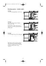
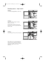
OPTION 1

and Standpipe Ø38mm with Air Gap.

OPTION 2

with Waste Disposal. Standpipe

Ø38mm with Air Gap.

PLEASE NOTE: It is NOT recommended to

connect the 

to any part of the Waste

Disposal System.

OPTION 3

using Sink Trap with Drain Hose Joiner.

NOTE: Options 1 and 2 are the preferred options.
Drains will need to be separated to satisfy Kosher
requirements. We suggest you confirm acceptability
with your local Rabbi in respect to Kosher
installations.

R

R

R

R

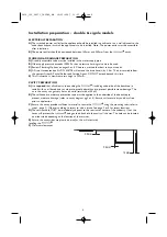
Plumbing options - single models

WASTE

VALVE

WATER
SUPPLY

200mm
MINIMUM
BENDS RADIUS
FROM VALVE

POWER
OUTLET

WASTE

( 750 mm - 882.5mm )

WASTE

VALVE

WATER
SUPPLY

200mm
MINIMUM
BENDS RADIUS
FROM VALVE

POWER
OUTLET

WASTE

( 750 mm - 882.5mm )

WASTE
DISPOSAL

WASTE

VALVE

WATER
SUPPLY

200mm
MINIMUM
BENDS RADIUS
FROM VALVE

POWER
OUTLET

DRAIN
HOSE
JOINER

( 750 mm - 882.5mm )

150mm

MIN

13

5019_102_00273_INSTAL_GB  30-05-2007  13:25  Pagina 13

Summary of Contents for KDDD 6010

Page 1: ...KDDS 6010 KDDD 6010 Assembly instructions 5019_102_00273_INSTAL_GB 30 05 2007 13 25 Pagina 1 ...

Page 2: ...5019_102_00273_INSTAL_GB 30 05 2007 13 25 Pagina 2 ...

Page 3: ...models 13 Installation instructions 14 Step 1 moving the product into the cavity 14 Step 2 removing the tub 15 Step 3 adjusting the feet double models only 16 Step 4 securing the product 17 Step 5 refitting the tub 17 Step 6 connecting the drain hoses 18 Step 7 connecting the inlet hose and power supply 19 Step 8 measuring the toe kick 19 Step 9 trimming the toe kick double models only 20 Step 10 ...

Page 4: ... the circuit breaker Ensure all water connections are turned OFF It is the responsibility of the plumber and electrician to ensu re that each installation complies with all Codes and Regulations Important These instructions must be followed precisely to ensure correct venting and operation of the In the event of a fault related to the incorrect installation the installer will be liable for any rep...

Page 5: ...toe kick kit Moisture Protection Tape 1 Clamp 1 Drain Hose Support 1 Drain Hose Joiner 1 Wire Clip 1 Phillips 16mm Screws 5 Moisture Protection Tape 1 SINGLE MODELS INSTALLATION KIT Clamp 1 Wooden Chopping Board Tape Measure Spirit Level Safety Glasses Utility Knife Pencil Side Sandpaper Drill No 2 Phillips Bit Phillips Screwdriver Flat Screwdriver Adjustable Wrench or M5 Socket Ø50mm Hole Saw Cut...

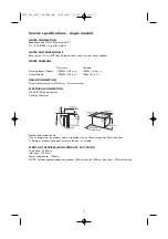
Page 6: ...ounding the including underside of the benchtop is sealed with an oil based paint or moisture proof polyurethane to prevent possible steam damage The air in the cavity can get very hot and humid saturated at 50oC B The self adhesive moisture protection tape must be applied to the underside of the benchtop to prevent moisture damage refer to cavity diagram pg 3 or 5 Ensure surfaces are dry and dust...

Page 7: ...conductor can result in a risk of electric shock Check with a qualified electrician or service representative if you are in doubt as to whether the appliance is properly earthed B This appliance is equipped with a power supply cord having an equipment earthing conductor and an earthing plug The power supply plug must be plugged into an appropriate outlet that is installed and earthed in accordance...

Page 8: ...EXIT POINT Drain hose 2250mm Inlet hose 1750mm Power supply cord 1965mm NOTE Services approximately exit product 189mm from left 550mm from front 793mm from top Prefinished model shown For an Integrated the product depth is specified with an 18mm Integrated Panel thickness Depth of product excludes Curvature 30mm or Handle TOE KICK DEPTH 67mm less the Toe Kick Panel thickness Minimum Panel thickne...

Page 9: ...ered to prevent damage to the power cord of hoses The cavity double models Min thickness of cavity sides is 16mm Ø50mm services hole immediately adjacent to corner can be either side 600mm 580mm throughout cavity 822 5mm 882 5mm 109 5mm 97mm 645 5mm Screw 14mm From front of cabinetry 90 10mm Moisture Protection Tape 100mm 505m m benchtop moisture protection tape 10mm 9 5019_102_00273_INSTAL_GB 30 ...

Page 10: ...ggest you confirm acceptability with your local Rabbi in respect to Kosher installations R R R R Plumbing options double models WASTE VALVE WATER SUPPLY 200mm MINIMUM BENDS RADIUS FROM VALVE POWER OUTLET WASTE 750 mm 882 5mm PRESA DI ALIMENTAZIONE WASTE VALVE WATER SUPPLY 200mm MINIMUM BENDS RADIUS FROM VALVE POWER OUTLET WASTE 750 mm 882 5mm WATER DISPOSAL 150mm MIN PRESA DI ALIMENTAZIONE VALVE W...

Page 11: ...m waste tee ELECTRICAL CONNECTION 220 240 VAC power outlet 4 5Amps Minimum Prefinsished model shown For an Integrated the product depth is specified with an 18mm Integrated Panel thickness Depth of product excludes Curvature 30mm or Handle LENGTH OF SERVICES FROM PRODUCT EXIT POINT Drain hose 2250mm Inlet hose 1750mm Power supply cord 1965mm NOTE Services approximately exit product 189mm from left...

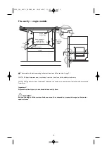
Page 12: ...cent cabinetry must not extend above cavity base WARNING Ensure the edges of the services hole are smooth or covered to prevent damage to the power cord or hoses The cavity single models Minimum thickness of cavity sides is 16mm 90 Ø50mm services hole can be either side immediately adjacent to corner 600mm 580mm throughout cavity 412mm 67mm 97mm Moisture Protection Tape 100mm 505m m benchtop moist...

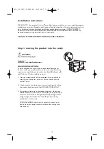
Page 13: ...Kosher requirements We suggest you confirm acceptability with your local Rabbi in respect to Kosher installations R R R R Plumbing options single models WASTE VALVE WATER SUPPLY 200mm MINIMUM BENDSRADIUS FROMVALVE POWER OUTLET WASTE 750 mm 882 5mm WASTE VALVE WATER SUPPLY 200mm MINIMUM BENDSRADIUS FROMVALVE POWER OUTLET WASTE 750 mm 882 5mm WASTE DISPOSAL WASTE VALVE WATER SUPPLY 200mm MINIMUM BEN...

Page 14: ...allation requires two sets of tab pairs be used either A and B tab pairs or B and C tab pairs All tabs would be optimum 1 If the top installation tabs C are to be used fit to the chassis by inserting into the top slots as shown Ensure the tabs are fully locked in place 2 Check cavity for any obstructions that may interfere with sliding the product back Loosen the feet DOUBLE MODELS ONLY 3 Push pro...

Page 15: ... DOUBLE MODELS Release the tub by depressing the right hand tub clip and pushing it back 30mm Repeat on the left hand side 6 Lift the tub up off the drawer runners 7 Slide both runners back into the product 8 Place the tub onto the floor For SINGLE MODELS depending on the height of the cavity the tub will need to be supported eg on a chair Step 2 removing the tub 4 8 6 5 7 15 5019_102_00273_INSTAL...

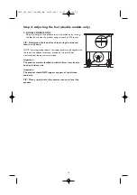
Page 16: ...pper panel may be aligned with the top of the adjacent cabinetry provided a minimum 5mm clearance from the bench is maintained Important The product must be levelled to within 2 5mm from front to back and side to side Important The product should NOT support any part of the kitchen cabinetry TIP Place a spirit level on the drawer runners to level the product Step 3 adjusting the feet double models...

Page 17: ...accommodate a maximum of 19mm vertical gap Step 4 securing the product 10 11 12 17 Important Before refitting the tub ensure the hoses are not twisted and the latches at the rear of each drawer runner are facing forward 13 To refit the tub make sure both of the latches at the rear of each drawer runner are facing forward Ensure hoses are hooping upward Place the tub on the half open drawer runners...

Page 18: ...ew supplied to prevent siphoning and to keep the drain hose s from kinking If required the Drain Hose s may be trimmed to a suitable length Important Minimum hole size to be connected to the drain system is 12 7mm The Drain Hose support must be used Ensure the Drain Hose s are fully extended to prevent sagging see diagram to left Drain Hose joiner must not support weight of hoses Keep excess lengt...

Page 19: ...cian NOTE SINGLE MODELS DO NOT HAVE A TOE KICK TO INSTALL PROCEED TO STEP 11 FINAL CHECK LIST Step 7 connecting the inlet hose and power supply 18 17 VALVE WATER SUPPLY 200mm MINIMUM BENDS RADIUS FROM VALVE POWER OUTLET WASTE WENT 19 19 Partially open the bottom drawer Turn Prefinished Toe Kick upside down and hold vertically against the bottom edge of the Tub side not the drawer front Mark the po...

Page 20: ...g them off 20 22 21 20 23 Partly open bottom drawer Position Toe Kick behind door and slide onto the mounting rails on the underside of tub 24 Close bottom drawer check if flush with adjacent cabinetry If required open drawer and adjust Note Clearance between Toe Kick and floor must be 12mm minimum When Toe Kick is in position open bottom drawer and gently fasten the Toe Kick screws on each side W...

Page 21: ... drained correctly Check water supply and drainage connection for leakage Repeat for each Drawer LEAVE ALL LITERATURE WITH CUSTOMER TROUBLE SHOOTING Excessive water remaining above the filter plate after the rinse cycle check for kinked drain hoses or blocked waste connection No water supply check water is connected ON and there is water pressure does not light up when the tub is opened ensure pow...

Page 22: ...5019_102_00273_INSTAL_GB 30 05 2007 13 25 Pagina 22 ...

Page 23: ...5019_102_00273_INSTAL_GB 30 05 2007 13 25 Pagina 23 ...

Page 24: ...5019 102 00273 Printed in Italy n 05 07 GB 5019_102_00273_INSTAL_GB 30 05 2007 13 25 Pagina 24 ...

Reviews: