background image

2-12

GAS HOOKUP & LEAK CHECK

1.

For Natural Gas:

 Connect a certified 1/2

gas  supply  pipe  to  the  inlet  side  of  the
regulator  from  a  natural  gas  supply,  ac-
cording to local codes requirements. Use
a pipe thread sealant that is certified for
use with natural gas at connections, where
required.

2.

For L.P. Gas:

 Connect the regulator hose

connector  to  a  full  20#  L.P.  tank,  and
hand-tighten it.

3.

Turn on the gas supply to the grill.

4.

Test all of the connections by brushing on
an approved noncorrosive leak-detection
solution. Bubbles will indicate a leak. Cor-
rect any leaks found.

ADJUSTING THE AIR SHUTTERS

1.

Light the grill using information in “Lighting
The Grill” on page 3-3.

2.

Observe  the  flame  to  determine  which
burners  need  adjustment,  and  how  the
flame is acting.

3.

Turn off the valve and wait until the grill
and burners are cool.

4.

Remove the grill grates and sear plates.

5.

Remove  the  burner  and  loosen  the  air
shutter adjustment screw.

a) If the flame is yellow (not enough air),

turn the air shutter counterclockwise.

b) If the flame is noisy, or lifts away from

the burner (too much air), turn the air
shutter clockwise.

Adjustment should be from 1/8

 to 1/4

.

6.

Tighten the air shutter adjustment screw.

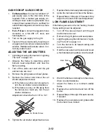
Air Shutter Screw

7.

Replace the burner sear plates and grates.

8.

Ignite the burners and check the flames.

9.

Repeat Steps 1 through 8, if needed. Only
adjust the burners that need adjustment.

LOW FLAME ADJUSTMENT

If the flame goes out on the “LO” setting, the low
flame setting must be adjusted.

1.

Turn off the valve and wait until the grill
and burners are cool.

2.

Remove the grill grates and sear plates.

3.

Light the grill using the information in “Light-
ing The Grill” on page 3-3.

4.

Turn the burner to its lowest setting and
remove the knob.

5.

Hold the valve stem with pliers and insert
a thin flat-blade screwdriver into the shaft.

6.

Watch the flame and slowly turn the screw-
driver counterclockwise.

7.

Adjust  the  flame  to  a  minimum  stable
flame.

8.

Replace the control knob and turn off the
burner.

9.

Repeat Steps 3 through 8 for each burner,
if needed.

10. Replace the sear plates and grates after

the burners have cooled.

Valve Stem

Summary of Contents for 4317333

Page 1: ...TECHNICAL EDUCATION JOB AID 4317333 KAC 32 OUTDOOR GAS GRILL Models KFGR270LSS KFGR274LSS KFGR292LSS KFGR364LSS KBGN274LSS KBGN292LSS KBGN364LSS ...

Page 2: ...Job Aid and Service Manual For specific information on the model being serviced refer to the Use and Care Guide provided with the grill GOALS AND OBJECTIVES The goal of this Job Aid is to provide detailed information that will enable the service technician to properly diagnose malfunctions and repair the KitchenAid Outdoor Gas Grill The objectives of this Job Aid are to Successfully perform necess...

Page 3: ...2 6 Rotisserie Electrical Requirements 2 8 Converting To Natural Or L P Gas 2 9 PRODUCT OPERATION 3 1 Features 3 1 Lighting The Grill 3 3 COMPONENT ACCESS 4 1 Component Locations 4 1 Removing The Control Panel Spark Module And Ignition Switch 4 2 Removing The Infrared Burner Ignitor Thermocouple 4 4 Removing The Infrared Burner 4 6 Removing A Burner Burner Ignitor Baso Gas Valve And Burner Gas Val...

Page 4: ... iv NOTES ...

Page 5: ...ll you how to reduce the chance of injury and tell you what can happen if the instructions are not followed You can be killed or seriously injured if you don t immediately follow instructions You can be killed or seriously injured if you don t follow instructions Electrical Shock Hazard Plug into a grounded 3 prong outlet Do not remove ground prong Do not use an adapter Do not use an extension cor...

Page 6: ...n to the State of California to cause cancer birth defects or other repro ductive harm and requires businesses to warn of potential exposure to such sub stances WARNING This product contains a chemical known to the State of California to cause cancer birth defects or other reproductive harm This appliance can cause low level expo sure to some of the substances listed in cluding benzene crystalline...

Page 7: ... PRESENT BRAND KITCHENAID PRODUCT IDENTIFICATION FG FREESTANDING GRILL BG BUILT IN GRILL MERCHANDISING SCHEME R L P GAS CONVERTIBLE N NATURAL GAS CONVERTIBLE CAPACITY SIZE SERIES CONFIGURATION 1ST POSITION 2 2 BURNERS DIRECT COOKING 3 3 BURNERS DIRECT INDIRECT COOKING 4 4 BURNERS DIRECT INDIRECT COOKING 2ND POSITION 7 27 6 36 9 39 8 48 FEATURES 0 BASE MODEL 2 INTEGRATED ROTISSERIE INTEGRATED SIDE ...

Page 8: ...EL LOCATION The Model Serial Number label location is shown below NOTE The label is located behind the control panel You must remove the smoker tray to read the label Model Serial Number Location Located Behind The Control Panel ...

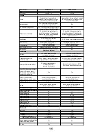
Page 9: ...emovable SS side shelves Fold down removable SS side shelves Storage Bin Yes Holding shelf inside the cabinet doors one on each door Yes Holding shelf inside the cabinet doors one on each door Yes Holding shelf inside the cabinet doors one on each door Performance Burners 2 SS Burners double U shaped 22 5K BTU each burner 2 SS Burners double U shaped 22 5K BTU each burner 2 SS Burners double U sha...

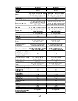
Page 10: ...urners double U shaped 22 5K BTU each burner 2 SS Burners double U shaped 22 5K BTU each burner V shaped sear plates for distributing heat Yes SS Slope Grease drains forward Long pins hold sear plates in place Yes SS Slope Grease drains forward Long pins hold sear plates in place Infrared rotisserie back burner SS ceramic infrared burners 14 5K BTU infrared rotisserie back burners SS ceramic infra...

Page 11: ...stributing heat Yes SS Slope Grease drains forward Long pins hold sear plates in place Yes SS Slope Grease drains forward Long pins hold sear plates in place Infrared rotisserie back burner SS ceramic infrared burners 14 5K BTU infrared rotisserie back burners SS ceramic infrared burners 14 5K BTU infrared rotisserie back burners Heavy Duty Rotisserie with Motor and Spit 20 pounds turkey Motor sea...

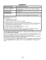
Page 12: ... to correct defects in materials or workmanship Service must be provided by a KitchenAid designated service company Replacement parts for components if defective in materials or workmanship Replacement parts for the stainless steel burners for rust through resulting from defective materials or workmanship Service must be provided by a KitchenAid designated service company KITCHENAID AND KITCHENAID...

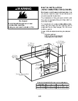
Page 13: ...his grill on or near combustible materials Doing so can result in death or fire WARNING If you plan to use a combustible enclosure return this grill and replace it with the model that is manufactured for use in a combustible enclosure Clearance to combustible construction for built in non combustibleconstruction and portable grills A minimum of 12 30 5 cm must be main tained between the grill hood...

Page 14: ...e free and clear from debris 8 Inspect the gas cylinder supply hose be fore each use of the grill If the hose shows excessive abrasion or wear or is cut it MUST be replaced before using the grill Contact your dealer and use only replace ment hoses specified for use with the grill 9 Visually check the burner flames They should be blue Slight yellow tipping is normal for L P gas 10 Check and clean b...

Page 15: ...e Batterymarch Park Quincy Massachusetts 02269 CSA International 8501 East Pleasant Valley Rd Cleveland Ohio 44131 5575 IMPORTANT This grill is manufactured for outdoor use only For grills that are to be used at elevations above 2000 feet orifice conversion is re quired see Gas Supply Requirements on page 2 6 It is the responsibility of the installer to comply withtheminimuminstallationclearancess...

Page 16: ... Not All Models Have Side Trays 23 58 4 cm 25 1 2 64 8 cm 26 66 0 cm 34 86 4 cm 24 5 8 62 5 cm 36 91 4 cm Portable Models 11 1 8 28 3 cm 3 5 8 9 2 cm 1 2 Male NPT Locking Front Casters A minimum of 12 30 5 cm must be main tained between the grill hood sides and back and any combustible construction A 12 30 5 cm minimum clearance must also be main tained below the cooking surface and any combustibl...

Page 17: ...may be obtained from CSA International 8501 East Pleasant Valley Rd Cleveland Ohio 44131 5575 12 30 5 cm Minimum To Any Accessory 2 5 1 cm Minimum To Open Hood 2 1 4 5 7 cm 10 7 8 27 0 cm 7 3 8 18 7 cm 19 48 3 cm 35 1 2 90 2 cm Optional Custom Access Doors 22 57 2 cm Gas Line Location At Rear Of Grill 1 1 8 2 9 cm 6 15 2 cm Minimum Clearance For Rotisserie A B Counter or Support Surfaces Must Be L...

Page 18: ...any pressure testing of the gas supply piping system at test pressures equal to or less than 1 2 psig 3 5 kPa PORTABLE GRILLS L P Gas This grill is equipped for use with an L P gas fuel tank It is design certified by CSA Interna tional for local L P gas supply or for Natural gas with appropriate conversion L P Gas From A Local L P Gas Supply IMPORTANT The gas installation must con form with local ...

Page 19: ...m A Local L P Gas Supply Conversion must be made by a qualified gastechnician Thequalifiednaturalgastech nician shall provide the L P gas supply to the selected grill location in accordance with the National Fuel Gas Code NFPA 54 and local codes To convert to L P gas the L P Gas Conversion Kit 4396312 must be used Fol low the instructions included with the kit L P Gas Conversion Using An L P Fuel ...

Page 20: ... adequate Check with a qualified electrician if you are not sure whether the grill is properly grounded Do not ground to a gas pipe A 120 volt 60 Hz AC only 15 ampere electri cal supply is required ROTISSERIE ELECTRICAL REQUIREMENTS Electrical Shock Hazard Plug into a grounded 3 prong outlet Do not remove ground prong Do not use an adapter Do not use an extension cord Failure to follow these instr...

Page 21: ... 2 57 Infrared Burners 4 55 Grill Burners 2 77 Smoker Burners 1 Brass Elbow 3 8 Flare Fitting To 1 2 NPT 1 L P Hose Regulator Assembly Fire Hazard Shut off gas supply line valve Make all conversions before turning gas supply valve back on Failure to follow these instructions could result in explosion fire or other injury WARNING CONVERTING THE GRILL To convert the grill for use with either Natural...

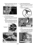
Page 22: ...ner off the gas valve orifice d Use a 1 2 deep socket and remove the orifice from the smoker burner gas line Replace the orifice with the proper conversion orifice 66 NAT or 77 L P Grill Gas Valve Shown With Front Panel Removed Grill Orifice Front View From Burner Box 4 To convert the smoker burner a Remove the grill burners from the grill see step 2 on page 4 8 for the proce dure b Remove the two...

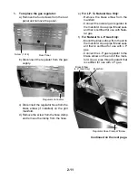
Page 23: ...the natural gas regulator to the manifold Use a pipe thread seal ant that is certified for use with Natu ral gas f For Natural To L P Gas Only Mount the brass elbow from the kit to the manifold Use a pipe thread seal ant that is certified for use with L P gas Connect the L P gas regulator to the brass elbow on the end of the mani fold Use a pipe thread sealant that is certified for use with L P ga...

Page 24: ...me is yellow not enough air turn the air shutter counterclockwise b If the flame is noisy or lifts away from the burner too much air turn the air shutter clockwise Adjustment should be from 1 8 to 1 4 6 Tighten the air shutter adjustment screw Air Shutter Screw 7 Replacetheburnersearplatesandgrates 8 Ignite the burners and check the flames 9 Repeat Steps 1 through 8 if needed Only adjust the burne...

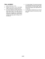
Page 25: ...hat hold on the front panel to locate the nameplate For a Natural Gas Conversion check the box next to Natu ralGas ortheboxnextto LPGas forL P Conversion 4 In the last page of the owners manual writethetypeofconversionyouperformed Also record the conversion date and the technician company that performed the conversion 5 On the grill is a red label where you should also mark the type of conversion ...

Page 26: ...2 14 NOTES ...

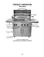
Page 27: ...S Fold Away Shelf Typical Carted Model Shown Not All Features Are Available On All Models Heavy Duty Locking Casters Large Storage Area Removable Grease Tray Smoker Tray Infrared IR Burner Ignition Switch 9 Volt Battery Compartment ...

Page 28: ...e right amount of heat for exceptional cooking Direct Or Indirect Cooking Sear food di rectly over the heat source or indirectly cook the food by utilizing reflected heat As the heat rises it reflects off the lid and the inside sur faces and slowly cooks the food evenly on all sides Smoke Flavoring Every grill features a gas powered smoker drawer Use mesquite hickory black walnut or orange chips t...

Page 29: ... a time 1 Do not lean over the burners Push in and turn to LITE the control knob for the burner you wish to use 2 Push in the burner ignitor button You will hear the snapping sound of the spark Keep the burner ignitor button pushed in untiltheburnerlights Makesuretheburner is lit Repeat for each of the other burners as needed IMPORTANT If the burner does not light im mediately turn the burner knob...

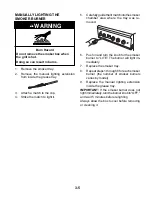
Page 30: ... does not lightimmediately turntheburnerknobto OFF and wait 5 minutes before relighting MANUALLY LIGHTING THE INFRARED IR ROTISSERIE BURNER 1 Remove the manual lighting extension from inside the grease tray 2 Attach a match to the clip 3 Strike the match to light it 4 Carefully hold the lit match close to the infrared burner 5 Push in and turn the infrared burner con trol knob to LITE 6 Push in th...

Page 31: ... each smoker burner the number of smoker burners varies by model 9 Replace the manual lighting extension inside the grease tray IMPORTANT If the smoker burner does not lightimmediately turntheburnerknobto OFF and wait 5 minutes before relighting Always allow the box to cool before removing or cleaning it MANUALLY LIGHTING THE SMOKER BURNER 1 Remove the smoker tray 2 Remove the manual lighting exte...

Page 32: ...3 6 NOTES ...

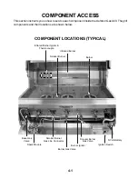
Page 33: ...oor Gas Grill The grill components and their locations are shown below COMPONENT ACCESS Infrared Burner Ignitor Thermocouple Infrared Burner Smoker Burner Burner Baso Gas Valve Spark Module Smoker Burner Gas Valve Burner Ignitor Ignition Switch 9 Volt Battery Smoker Burner Gas Line Connector Burner Gas Valve ...

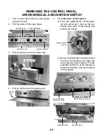
Page 34: ... Spark Module Bezel Screw 1 of 2 b Removethetwobottomoutsidescrews from the control panel then lower the control panel and tip it forward Provide a padded surface to avoid damage to the finished surface and rest the panel on the support 1 Turn off and disconnect the gas supply going to the grill 2 Pull the knobs off the gas valves Knobs Bezels Smoker Tray Grease Tray Ignition Switch 4 Pull out and...

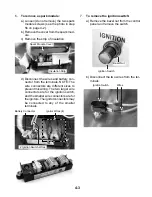
Page 35: ...Disconnect the wires and battery con nector from the terminals NOTE The wire connectors are different sizes to prevent miswiring The two larger wire connectors are for the ignition switch and the smaller wire connectors are for theignitors Theignitorconnectorsmay be connected to any of the smaller terminals Battery Connector Ignitor Wires 4 Ignition Switch Wires b Disconnect the two wires from the...

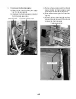
Page 36: ... e Remove the screw from the infrared burner ignitor bracket and remove the ignitor from the unit IR Burner Ignitor Thermocouple Cover Screw IR Burner Ignitor Screw Cut Wire Tie Infrared Burner Ignitor Wire 2 To remove the infrared burner ignitor a Removethecontrolpanelandthespark module see pages 4 2 and 4 3 for the procedures b Disconnect the infrared burner ignitor wire from the spark module te...

Page 37: ...so gas valve c Remove the rear panel and the infrared burner ignitor thermocouple cover see steps 2c and 2d on page 4 4 d Push the thermocouple out of its hold ing clip e Pull the sensor tube through the two access holes at the rear of the unit and remove the thermocouple Thermocouple Connector Thermocouple Clip Access Holes Baso Gas Valve ...

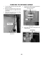
Page 38: ... see step 2 on page 4 4 for the procedure 3 Disconnect the top 5 8 gas line fitting going to the infrared burner Disconnect Gas Line Here 4 Remove the screw from the rear access panel and remove the panel 5 Disconnect the gas line fitting from the infrared burner Rear Access Panel Infrared Burner Gas Line Fitting Screw Rear Of Unit Rear Of Unit ...

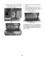
Page 39: ...burner panel from the unit Thermocouple Out Of Clip 6 Push the thermocouple out of its holding clip and position it in the access opening Access Opening 3 Panel Screws Infrared Burner Panel REASSEMBLY NOTE Turn on the gas to the grill and test all of the connections by brushing on an approved noncorrosive leak detection solution Bubbles will indicate a leak Correct any leaks found ...

Page 40: ...d disconnect the gas supply going to the grill 2 To remove a burner a Remove the grates the griddle if in stalled and the sear plates b Lift the rear of the burner pull the air shutter off the gas valve orifice and remove the burner Burner Air Shutter With Insect Guard Grates Sear Plates ...

Page 41: ... the top of the cover forward and remove it d Remove the screw from the ignitor bracket and collector box NOTE Hold the collector box while removing the screw since the screw secures both the ignitor and the collector box 5 8 Nuts Front Cover e Disconnect the burner ignitor wire con nector from the spark module Burner Ignitor Ignitor Wires Continued on the next page Bracket Collector Box Screw Col...

Page 42: ...g on an approved noncorrosive leak detection solution Bubbles will indicate a leak Correct any leaks found Manifold Burner Gas Valve 4 To remove the baso gas valve a Remove the control panel see page 4 2 for the procedure b Removethethermocoupleandgasline connectors from the baso gas valve c Unscrew the baso gas valve from the manifold and remove it NOTE The two valves are replaced as an assembly ...

Page 43: ...nd of the smoker burner Smoker Burner Bracket Screws 1 of 2 Smoker Ports Facing Up Continued on the next page c Remove the two screws from the rear burner rail and move the rail to the rear of the burner box d Pull the smoker burner off the gas valve orifice e To remove the smoker burner orifice unscrew it from the gas valve Smoker Burner Orifice Smoker Burner Burn Hazard Do not remove the smoker ...

Page 44: ...the smokerburner disconnectthelinefrom the 90 elbow at the burner 90 Elbow c Remove the flex gas line connector from the smoker burner gas valve d Unscrew the smoker burner gas valve from the manifold REASSEMBLY NOTES When you replace a gas valve use an appropriate thread sealant that is approved for use with L P gas Turn on the gas to the grill and test all of the connections by brushing on an ap...

Page 45: ...ery a Pull the battery holder cover out at the bottom to release the magnetic seal b Pull the battery holder out of the control panel c Remove the battery from the holder and unclip the connector from the bat tery terminals Battery Connector Battery Holder Cover ...

Page 46: ...4 14 REMOVING A CABINET DOOR 1 To remove the cabinet door open the door 2 Lift the door straight up and unhook the hinge pins from the hinge hangers Lift Door Straight Up ...

Page 47: ...R READY TO IDENTIFY YOU AS AN AUTHORIZED SERVICER FOR LITERATURE ORDERS PHONE 1 800 851 4605 IN CANADA FOR PRODUCT SPECIFICATIONS AND WARRANTY INFORMATION CALL 1 800 461 5681 FOR TECHNICAL ASSISTANCE WHILE AT THE CUSTOMER S HOME CALL THE TECHNICAL ASSISTANCE LINE 1 800 488 4791 HAVE YOUR STORE NUMBER READY TO IDENTIFY YOU AS AN AUTHORIZED SERVICER FOR WHIRLPOOL PRODUCTS 1 800 253 1301 FOR KITCHENA...

Page 48: ......

Reviews: