Kitagawa BBT200 Instruction Manual Download Page 24


・ 

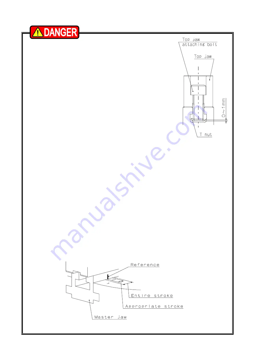
If the screw-in depth of the jaw attaching bolt to the T nut 

is shallow, the T nut will break, and this is dangerous as 

the jaw and work will fly out. If the attaching bolt is too 

long and comes out from the bottom of the T nut as well, 

this is dangerous as the jaw and work will fly out since 

the top jaw is not fixed. Therefore, the overall length of 

the jaw attaching bolt must be approximately 0 to -1mm 

from the bottom of the T nut (Refer to Fig.10). 

・ 

Use the T nut and the attaching bolts attached to the 

chuck and do not use bolts other than these. If 

commercially available bolts are used for an unavoidable 

reason, use bolts at the strength classification 12.9 

(strength classification 10.9 for M22 or more) or more, 

and pay sufficient attention to the length.


Fig.10 

・ 

Do not rotate the chuck so that the T nut is loosened causing the jaw to fly out. 

・ 

Check that the reference mark on the side of the No. 1 master jaw is within the 

range of the entire stroke as shown in Fig. 11. Full stroke the jaw at least once 

a day to check it before work or when supplying grease, etc. If it goes out of 

the range of appropriate stroke due to loosening of the draw nut, etc., the work 

may not be gripped, and this is dangerous as the work will fly out.


・ 

When gripping the work, use it by keeping the position of the master jaw 

within the appropriate stroke range. Gripping in the center of the stroke is the 

most stable for the mechanism, and the best precision can be obtained. 


・ 

When gripping near the stroke end, the work may not be gripped 

sometimes according to the deviation, etc., of the gripping part allowance 

of the work, and this is dangerous as the work will fly out.


・ 

When gripping near the stroke end, the chuck may break and the chuck or 

work could fly out.


Fig.11 


23 

Summary of Contents for BBT200

Page 1: ...fore installing operating or maintaining this equipment carefully read this manual and the safety labels attached to the equipment Failure to follow these instructions and safety precautions could res...

Page 2: ...shown below depending on the damage of risk including the seriousness of the harm that could result Please sufficiently understand the meanings of these terms and follow the instructions for safe ope...

Page 3: ...specified in this manual please confirm them with our company or distributor before performing them Guarantee and Limitation of Liability The guarantee period of this product is 1 year after delivery...

Page 4: ...Soft Jaw 22 4 1 Attachment of soft jaw 4 2 Forming soft jaw with outside diameter gripping 4 3 Forming soft jaw with inside diameter gripping 4 4 Forming method when you use forming jig 5 Usage 27 5...

Page 5: ...ng of attachment 8 2 In the case that the back plate must be manufactured BBT200 series 8 3 In the case of with back plate BBT200A series 8 4 Attachment of chuck 9 Other Information 47 9 1 About stand...

Page 6: ...1 Structural Drawing and Parts List 1 1 Type display Type display as shown below Fig 1 1 2 Structural drawing Fig 2 5...

Page 7: ...ng safe design maintenance and erroneous action prevention of the hydraulic system to maintain the gripping force of the chuck is extremely important Thoroughly read the Important Safety Precautions o...

Page 8: ...er jaw 2 15 Set screw 1 4 Soft jaw 2 16 Steel ball 1 5 T nut 2 17 Grease nipple 2 or 4 6 Plunger nut 1 18 Hex key 1 7 Draw nut 1 19 Hex key 1 8 Cover 1 20 Hex key 1 9 Coil spring 1 21 Hex key 1 10 Han...

Page 9: ...r All Users Close door before rotating spindle If the door is not closed you may touch the rotating chuck or the work may fly out which is very dangerous In general the safety interlock function which...

Page 10: ...the draw pipe must not exceed the allowable maximum input force Refer to pages 16 21 Input must match the specification of the chuck Adjust the hydraulic pressure to the cylinder so that the input for...

Page 11: ...oment out of the range of the gripping force limit table The chuck will break and the chuck and work will break and fly out For All Users When the protrusion of the work is long support it with the st...

Page 12: ...hen the cylinder of our company and a high pressure chuck of other company are combined confirmation is necessary If one of the abnormal events shown below occurs during operation immediately stop the...

Page 13: ...insufficient or excessive the bolt will break which is dangerous as the chuck or work will fly out Fix the lathe spindle or the chuck when you tighten bolts Your hand could slip and get injury when yo...

Page 14: ...ng force will be lost instantly which is dangerous as the work will fly out If the draw pipe is unbalanced vibration occurs the screw is broken and the gripping force will be lost instantly which is d...

Page 15: ...ure due to lower hydraulic pressure lowers the gripping precision and causes abnormal wearing and seizing etc This is dangerous as the work could fly out from a drop in the gripping force For All User...

Page 16: ...2 39 43 2 51 7 Gripping range outside diameter gripping mm 19 170 23 210 41 254 47 315 Mass standard soft jaw included kg 11 4 21 5 30 8 50 2 Moment of inertia kg m2 0 048 0 137 0 292 0 706 Matching c...

Page 17: ...ng force specified in the specification is the value under the following conditions The Kitagawa standard soft jaw is used as the jaw The attaching bolts of the soft jaw are tightened at the specified...

Page 18: ...of the soft jaw top surface height from the chuck surface to the top surface of the jaw 17 To avoid serious accidents caused by the chuck or work flying out Determine the gripping force required for...

Page 19: ...this is dangerous Vibration is generated if there is unbalance due to the work and the jig etc Vibration decreases process precision and shortens the working life of the chuck even possibly breaking...

Page 20: ...the centrifugal force generated at the top jaw will increase It is necessary to examine the dynamic gripping force considering the centrifugal force and to use the machine at a rotation speed that ca...

Page 21: ...Fig 8 20...

Page 22: ...ss due to the centrifugal force becomes large The centrifugal force is proportional to the square of the rotation speed The required static gripping force and input force required at the rotation spee...

Page 23: ...ng conditions etc Use the T nut so that it does not come out from the master jaw Refer to Fig 9 It if the T nut comes out from the master jaw the master jaw and T nut will break causing the work to fl...

Page 24: ...rotate the chuck so that the T nut is loosened causing the jaw to fly out Check that the reference mark on the side of the No 1 master jaw is within the range of the entire stroke as shown in Fig 11 F...

Page 25: ...g By operating the switch valve grip the plug for forming in the D part At this time grip by pressing the plug on the chuck front surface in order for the plug not to be tilted Repeat chucking several...

Page 26: ...ng on the jaw in order for the ring not to be tilted Repeat chucking several times to stabilize the ring 4 Forming Process the gripping part dimension D of the work in the state that the ring is kept...

Page 27: ...end surface of the jig for forming onto the jaw so as not to generate run out Check that it is gripping almost in the center of the appropriate stroke Set the hydraulic pressure when forming slightly...

Page 28: ...rk and the cutting conditions Pipe shape work etc may be distorted if they are tightened at a high gripping force 5 1 Precautions during gripping work with chuck When gripping a work with the chuck do...

Page 29: ...ent serration pitch from the master jaw The engagement of the crests of the serration will become insufficient therefore the serration crests will break when gripping the work and this is dangerous as...

Page 30: ...ropriate for the dynamic gripping force and machine rigidity 2 Interference contact impact Before starting work check that the top jaw locator work etc and the tool and the tool post etc do not interf...

Page 31: ...BT212 42 94 5 30 or less A B Additional process impossible dimension C Processible depth of tapping or drilling a hole The chuck can be modified only in the manufacturer permissible range This will no...

Page 32: ...aw several times without gripping work 2 Grease to use Use the designated grease specified in Table 5 If grease other than the designated grease is used sufficient effect may not be obtained Table 5 G...

Page 33: ...gestion If large amounts are swallowed do not induce vomiting Obtain medical attention Please refer to each MSDS about the grease and the anti rust oil which you prepared 6 3 Disassembling Disassembli...

Page 34: ...ces stagnate inside the chuck it will lead to insufficient stroke and a drop in the gripping force and this is dangerous as the work will fly out Check each part carefully and replace any part that is...

Page 35: ...ation Supply grease from the grease nipple and open and close the jaw several times without gripping a work The Work slips The rotation speed is too high Swinging occurs due to incorrect alignment of...

Page 36: ...op using the machine Continuous use of a broken product or a defective product may cause a serious accident by the chuck or the work flying out Only experienced and trained personnel should do repairs...

Page 37: ...ufacturers personnel who attach a chuck to a machine Please read following instruction carefully when you attach or detach a chuck to machine and please sufficiently understand and follow the instruct...

Page 38: ...fer to Fig 13 If the hydraulic oil stagnates inside the cylinder oil leakage occurs which may cause a fire Install after removing the dust inside the pipe completely Add a filter to the pressure suppl...

Page 39: ...71 4 5 M90 2 A 43 0 036 BBT212 SS2110K M115 2 35 35 110 0 071 4 5 M115 2 A 41 5 The dimension L in Fig 14 is determined from the distance A between the cylinder adapter and the back plate Example In t...

Page 40: ...e screw of the draw pipe is loose vibration may occur resulting in breakage of the screw If the screw breaks the gripping force will be lost instantly which is dangerous as the work will fly out If th...

Page 41: ...ve the bolt will break which is dangerous as the chuck or work will fly out Use the bolts attached to the chuck and do not use other bolts However if you must use other bolts not provided by Kitagawa...

Page 42: ...end surface of the back plate and the spigot joint diameter can be raised by processing them after mounting to the installed machine Process the chuck attachment spigot joint diameter of the back pla...

Page 43: ...bolts that have at least a strength classification of 12 9 10 9 for M22 or more and be sure they are long enough Table 10 Bolt size Tightening torque M5 8 N m M6 13 N m M8 33 N m M10 73 N m M12 107 N...

Page 44: ...210A8 SS1881K M90 2 35 30 85 0 071 4 5 M90 2 A 61 0 036 BBT212A1 SS2110K M115 2 35 35 110 0 071 4 5 M115 2 A 71 5 The dimension L in Fig 18 is determined from the distance A between the cylinder adapt...

Page 45: ...the instruction manual for the cylinder for other items about the cylinder 2 Attach the cylinder to the spindle or the cylinder adapter Check the run out of the cylinder and if it is normal attach th...

Page 46: ...ping force and the work flying out 4 Attach the chuck matching to the attaching surface of the spindle or the back plate Turn the handle for connection to make a state that the chuck closely contacts...

Page 47: ...of the master jaw meets the line of the outside of the stroke mark Refer to page 23 A click stop rotation stopper is also attached to the draw nut so complete adjustment at the position where this res...

Page 48: ...rders This product is based on the following standards or orders Machinery directive 2006 42 EC Annex I EN ISO 12100 1 2003 A1 2009 EN ISO12100 2 A1 2009 EN ISO14121 1 2007 EN1550 1997 A1 2008 9 2 Inf...

Page 49: ...48 9 3 About disposal Ultimate disposal of this product should be handled according to all national laws and regulations...

Page 50: ......

Reviews: