Chapter 5. Inputs and Outputs
5-1
Chapter 5. Inputs and Outputs
Introduction
The
I/O
Menu is used to enter parameters for
setpoints, current output (4-20 mA, 0-20 mA),
serial port configuration, printer functions, and
PLC interface. This chapter covers the
functions in the
I/O
Menu. Explanations of
each of the functions are provided. Addition-
ally, detailed navigation procedures through
the menu tree are provided for the setpoint
and current output functions.
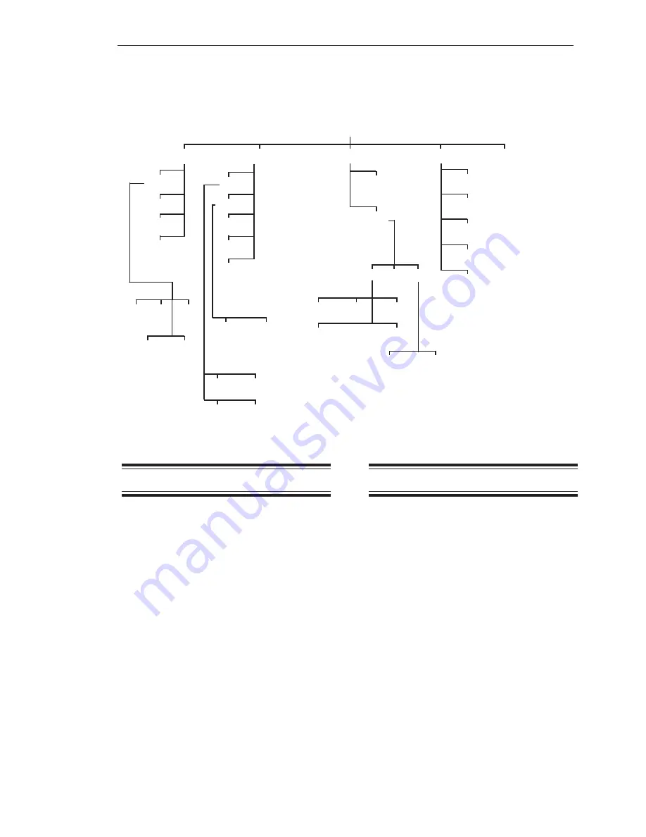
As shown in Figure 5-1, the
I/O
Menu has five
submenus:
1.
Setpt
— used to set up setpoints to
activate or deactivate a relay
2.
Iout
— used to set up current outputs
3.
Serl
— used to set up serial communica-
tions settings for use with a PLC,
printer, etc.
4.
Prnt
— used to direct output to a printer
5.
PLC
— used to set up communications
with a PLC
SetPt
The setpoint value is the weight measurement
in a vessel where you wish a device (for
example, a pump) to activate or deactivate.
The setpoint setup functions for each vessel
are accessed in this menu. They include
adding and deleting setpoints and selecting
activation levels, high or low activation,
deadband values, fail-safe parameters, and
net or gross weight.
The
Descriptions
section defines each of the
parameters. The
Setting Up the Setpoint
and
Setpoint Report
sections provide the detailed
procedures for using the Weigh II.
Descriptions
Set
This menu is used to select the setpoint to
be set up for the displayed vessel. Depending
on the options you selected for your Weigh II,
up to eight setpoints can be assigned per
Figure 5-1. The Input/Output Menu Tree
Tare
GO1
GO_ALL
Timed
PDly
Setpt
Iout
Serl
Prnt
PLC
Set
Report
Delete
Add
Set
Mode
Rprt
Delete
Add
HideS
Set
Val
I/O
Net/Grs
Fsafe
Hi/Lo
0-20ma
4/0ma
20ma
Net/Grs
Baud Addr Mode
Printer
Slave
4-20ma
Dead
1200
2400
4800
9600
19200
Fsafe
Summary of Contents for Weigh II
Page 12: ...2 4 Chapter 2 Hardware Installation...
Page 20: ...3 8 Chapter 3 Menu Tree Keyboard Functions and Quick Start...
Page 50: ...6 12 Chapter 6 Calibration...
Page 68: ...A 2 Appendix A Product Specifications...
Page 70: ...B 2 Appendix B Summary of Commands Used When Vessel Mounting Hot Keys...
Page 77: ...Appendix E E 1 This appendix not used at this time...
Page 78: ...Appendix E E 2...
Page 80: ...Appendix F Technical Drawings F 2...
Page 81: ...Appendix F Technical Drawings F 3...
Page 82: ...Appendix F Technical Drawings F 4...
Page 83: ...Appendix F Technical Drawings F 5...
Page 84: ...Appendix F Technical Drawings F 6...
Page 85: ...Appendix F Technical Drawings F 7...
Page 86: ...Appendix F Technical Drawings F 8...
Page 87: ...Appendix F Technical Drawings F 9...
Page 88: ...Appendix F Technical Drawings F 10...
Page 89: ...Appendix F Technical Drawings F 11...
Page 90: ...Appendix F Technical Drawings F 12...
Page 91: ...Appendix F Technical Drawings F 13...
Page 92: ...Appendix F Technical Drawings F 14...
Page 93: ...Appendix F Technical Drawings F 15...
Page 94: ...Appendix F Technical Drawings F 16...
Page 95: ...Appendix F Technical Drawings F 17...
Page 96: ...Appendix F Technical Drawings F 18...
Page 97: ...Appendix F Technical Drawings F 19...
Page 98: ...Appendix F Technical Drawings F 20...
Page 99: ...Appendix F Technical Drawings F 21...
Page 100: ...Appendix F Technical Drawings F 22...
Page 101: ...Appendix F Technical Drawings F 23...
Page 102: ...Appendix F Technical Drawings F 24...
Page 103: ...Appendix F Technical Drawings F 25...
Page 104: ...Appendix F Technical Drawings F 26...
Page 105: ...Appendix F Technical Drawings F 27...
Page 106: ...Appendix F Technical Drawings F 28...
Page 107: ...Appendix F Technical Drawings F 29...
Page 108: ...Appendix F Technical Drawings F 30...
Page 109: ...Appendix F Technical Drawings F 31...
Page 110: ...Appendix F Technical Drawings F 32...
Page 116: ...Appendix G Calculation of Maunal Calibration Parameters G 6...


