background image

DP485 Service Manual 

71 

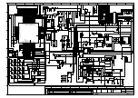
Schematic Diagrams of Module Board 

DBB

LCDWR

LCDCD

LCDCS

LCDD0

SCK

SDI0

LCD_D1

LCD_D2

LCD_D3

LCD_D4

LCD_D5

LCD_D6

LCD_D7

LCD_RD

SDI1_0

LCD_WR

1 of 3

NC

SPI LCM (VLCM)

LCM 

LCM

LCM

IIC

GPIO (VDD28)

JTAG (VDD28)

RF (VDD28)

KEYPAD (VDD28)

UART0 (VDD28)

EXTINT (VDD28)

RF_SPI (VDD28)

SPI0 (VDD28)

LED (VDDSD)

VDDLDOA0

VDDLDOA1

CLK (VDD28)

DIGTAL

B14


NC

C14


NC

A14


NC

A15


NC

B12


NC

C13


NC

C8


FMARK

D8


LCMRSTN

B11


SPI1_DI/LCMWR

A10


SPI1_DO

C10


SPI1_CLK/LCMCD

C9


SPI1_CS/LCMCS

B10


SPI1_CD/LCMD0

D6


SCK

A7


NC

C6


SDI0

C4


LCMD1/SDI1_0

C5


LCMD2

B4


LCMD3

A3


LCMD4

B3


LCMD5

E3


LCMD6

D3


LCMD7

C3


LCMRD

B7


NC

A6


NC

B6


NC

B8


SCL0

C7


SDA0

5T_EN


R3

5R_EN


U4

PC_SW


P4

KEYOUT0


U8

KEYOUT1


V6

KEYOUT2


U7

KEYOUT3


W6

KEYOUT4


U6

KEYIN0


U5

KEYIN1


V3

KEYIN2


W3

KEYIN3


V5

KEYIN4


W5

U0TXD


B2

U0RXD


D2

U1RXD


E2

U1TXD


A2

C11


EXTINT0

A11


KEYIN5

LED_RX


G18

LED_TX


F19

HE_EN


G19

FLASH_HLD


F18

H3


GPIO_0

F2


KEYIN7

H2


GPIO_2

F1


GPIO_3

E1


MTCK

B1


MTMS

SPI0_CLK


D16

SPI0_CS


B16

SPI0_DI


B15

SPI0_DO


C15

BB_SPI_CLK


C18

BB_SPI_DO


D18

BB_SPI_CS0


F17

RDA_SQL


G17

RDA_PDN


E17

FLASH_HLD


C19

WT_RST


C16

GPIO_60


B18

GPIO_58


A18

SPK_EN1


B19

SPK_EN2


C17

FLASH_WP


D17

NC


D15

PWM


G3

U2100-A

HS8861

R68

0R

J9

J12

R4

0R

1


CS

2


DO(IO1)

3


WP(IO2)

4


GND

DI(IO0)


5

CLK


6

7

HOLD(IO3)

8

VCC

9


G

ND

U0005

TC58CVG1S3H

C0044

1uF

D1

RB521S30

R1

10K

TP6

TP7

TP8

TP9

TP10

TP11

TP12

TP13

TP14

TP15

TP16

TP17

TP18

TP19

TP20

TP21

TP22

TP23

TP24

TP30

TP31

TP32

TP33

TP34

TP36

TP37

TP38

TP39

TP40

TP42

TP43

TP44

TP45

TP46

TP47

TP48

TP49

TP50

TP51

TP52

TP53

TP54

TP55

TP56

TP57

TP58

TP59

TP60

TP61

TP68

TP69

R2

10K

R9

R10

R11

10K

TP4

TP5

TP41

TP67

TP72

TP75

TP76

TP77

TP78

TP79

TP82

TP83

TP84

TP85

TP86

TP88

TP90

TP91

TP92

TP28

TP70

D2

RB521S30

R12

10K

C28
1uF

C144

103

FB105

0R

1

2

X100


32.768K

R133

10K

D105

RB521S

R20


10K

R21


10K

1

1


OSCI

2


OSCO

3


INT

4


VSS

SDA


5

SCL


6

CLKOUT


7

VDD


8

U6

C6
100nF

R27


10K

1

2

D3

RB521S

R28

R29

0R

HS_DET

ENC_0

ENC_1

ENC_2

ENC_3

PTT

LCD_RST

LCD_WR

LCD_CS

LCD_D0

LCD_D1

LCD_D2

LCD_D3

LCD_D4

LCD_D5

LCD_D6

LCD_D7

LCD_RD

U0RXD

U0TXD

BB_SPI_CLK

BB_SPI_CS0

BB_SPI_DO

FLASH_CLK


[1]

FLASH_CS


[1]

FLASH_DI


[1]

FLASH_DO


[1]

QT_DQTIN

KEYOUT0

KEYOUT1

KEYOUT2

KEYOUT3

KEYIN0

KEYIN1

KEYIN2

KEYIN3

SPK_EN2

SPK_EN1

AT_PDN

AT_SQL

APC_SW1

RX_LED

TX_LED

5R_EN

5T_EN

PWM

FP1

KEY2

KEY1

SPK_EN3

APC_SW2

[1]

FLASH_CS

[1]

FLASH_DI

FLASH_CLK


[1]

FLASH_DO


[1]

3V0

LCD_RS

EXT_PTT

3V0

[2]

U1RXD

DACS_SW1

LDAC_PC/TV

GPIO9

3V0

3V0

MADN_C

LCD_BL

KPLED_OUT

GPSENABLE

[2] GPIO7

GPIO5

[1]

SCL

[2]

U1TXD

[1]

SDA

3M

RTC_VCC

RTC_VCC

[1]

SCL

[1]

SDA

[2,3]

VBAT_3V6

[1]

DOWNLOAD

[1]

DOWNLOAD

Summary of Contents for DP485

Page 1: ...V220927 Kirisun Communications Co Ltd Professional wireless communication system solution supplier DP485 SERVICE MANUAL ...

Page 2: ...uit 8 4 6 Power Section 8 4 7 IC Description 9 4 7 1 Features of AT1846S 9 4 7 2 Port Description of AT1846S 10 4 7 3 Port Description of Master Chip HS8851 11 4 7 4 Feature Description of Semiconductor Devices 15 5 Feature Description and Parameter Setting 15 5 1 Stun Revive and Remote Monitor 15 5 2 Scan 16 5 3 Zones 16 5 4 Setting 16 5 5 TOT Time Out Timer 17 5 6 Emergency Alarm 17 5 7 Settings...

Page 3: ...l List Electronic Part 32 Table 1 Material List of Main Board 400 470MHz 32 Table 2 Material List of Main Board 137 174MHz 45 Table 3 Material List of Module Board 58 Appendix 3 Material List Structural Section 59 Appendix 4 Accessory List 62 Appendix 5 Schematic Diagrams and Layout Drawings 63 Schematic Diagrams of Main Board 63 Top Layer Layout Drawing of Main Board 69 Bottom Layer Layout Drawin...

Page 4: ...instructed for example a hospital a health center and an airport Explosive Gases You d better shut down the radio when you are in an area with explosive gas for example the lower deck of a hull a container or transport facility of fuel oil or chemicals or with chemical or particles dust or metallic dusts in the air or near a blast area or an electric blasting detonator Replacing or recharging the ...

Page 5: ...nce stations and dealers at preferential prices except those of discontinued products 2 External View and Keys 2 1 External View NO Description NO Description 1 Antenna 7 Power Volume Knob Turn it clockwise until a click is heard to power on the radio Turn it counterclockwise until a click is heard to power off the radio When the radio is on turn it to regulate the volume Flashing red light The ba...

Page 6: ... Press Press down and release quickly Press and hold Press down and hold still for a period which is set through the CPS customer programming software NO Programming Function Function Description 1 None The radio does not respond when this key is pressed 2 Battery Level Announcement Announce the current battery level 3 High Low Power Switch to high low power 4 Broadcast Call Initiate a broadcast c...

Page 7: ...annel dwelled on during scan and then continue scan 13 Repeater Talk Around On a repeater channel press it to enter exit repeater mode 2 3 LED Indicator LED Indication Radio State Red light on Transmitting signals Green light on Receiving signals Red Light Flashing Low battery Please charge it Green Light Flashing Scanning channels Orange Light Flashing In call hold state under digital mode Exit w...

Page 8: ... radio receives RF signals on the selected channel and the squelch level is reached the green LED glows to indicate that carrier is received When the selected channel is digital channel and when it received individual call group call or all call the radio will output the voice from the channel When the channel is analogue channel and when it received analogue signals with CTCSS matching the one on...

Page 9: ...DP485 Service Manual 6 4 Circuit Description 4 1 Circuit Diagram of Main Board 4 2 RF Circuit Diagram HS8851 ...

Page 10: ...put terminal of final power amplifier through a section of microstripe so as to minimize output power loss from impedance match failure afterwards the transmitted signal will enter the low pass filter through TX RX switch Low Pass Filter Circuit The low pass filter which suppresses harmonic wave is an advanced Chebyshev filter composed of lumped parameter inductor and capacitor On a certain basis ...

Page 11: ...ing of digital signal through DSP in HS8861 will be input to digital audio processor module for further processing and then be switched to analogue voice signal through DAC of codec the analogue voice signal will finally be amplified by external audio amplifier to drive the speaker 4 6 Power Section The radio applies 7 4V lithium ion battery for power supply RF power amplification and audio power ...

Page 12: ...Modulation and demodulation technique based on digital signal processing technology d TX path of direct frequency synthesis Modulation method of direct frequency synthesis TX filter based on digital signal processing technology TX modulation gain number is adjustable Digital voice activates TX control e High performance fractional PLL frequency synthesizer Fully integrated in chip RF VCO Fully int...

Page 13: ...n MODE VH SPI Interface is select SENB 8 Latch enable active low input for serial control bus AFOUT 9 Audio signal output to speaker NC 10 No connection MIC_IN 11 MIC input Cc 12 Compensation capacitor connection AVDD 13 Power supply NC 14 No connection RFIN 15 RF signal input AVDD 16 Power supply NC 17 No connection RFOUT 18 RF signal output NC 19 No connection NC 20 No connection AVDD 21 Power s...

Page 14: ...lse VL GPIO1 31 Gpio1 code_in code_out Gpio1 VH or VL it is the input output code data GPIO0 32 Gpio0 css_in css_out Gpio0 VH or VL it is the input output CTCSS CDCSS signal 4 7 3 Port Description of Master Chip HS8851 PIN NO Port NO Port Name Function E11 GPIO_D44 NC NC J19 BSENS MAND_IN IC level input under Man Down state L22 ADC_IN BAT_DET Battery capacity detection W13 GPIO_D7 PF Input from si...

Page 15: ...21 GPIO_D97 KEYPAD1 4 4 keys V22 GPIO_D10 KEYPAD4 4 4 keys F5 GPIO_D112 LCD_RS LCD AB19 LCD_CS1 LCD_RST LCD L21 SSI0_RX SSI0_RX FLASH P21 SSI0_TX SSI0_TX LCD FLASH N21 SSN0 LCD_CS LCD M21 SSN1 FLASH_CS FLASH F6 GPIO_D111 NC NC_GPIO R21 SSI0_CLK SSI0_CLK LCD FLASH A12 VOUT_D9 VIO_3V_C PMU_3V output J14 GPIO_D76 UART_RXD0 Serial port 0 J15 GPIO_D75 UART_TXD0 Serial port 0 F22 BAT_DET BAT_DET Battery...

Page 16: ... E13 GPIO_D48 5TC 5TC A13 VOUT_D3 3C PMU_3M output C13 GPIO_D52 DACS_SW1 DA_MCP4802 B13 GPIO_D47 5RC 5RC E12 GPIO_D50 LDAC_PC TV DA_MCP4802 C12 GPIO_D53 AFCO2 Speaker output MUTE A11 GPIO_D46 RDA_PDN RDA1846S A10 GPIO_D58 SPI CS RDA1846S F11 GPIO_D2 NC_GPIO B11 GPIO_D57 SPI CLK RDA1846S B10 GPIO_D56 SPI DA_OUT RDA1846S F10 GPIO_D0 RDA_SQL SQL E10 GPIO_D3 KEYPAD_BL Backlight control K18 GPIO_D107 N...

Page 17: ...o HS8851 after reception and demodulation by AT1846S D2 M_MICN NC NC E2 HP_MICN MIC1 Transmit MIC signals to HS8851 H5 DM USB_DM USB J5 DP USB_DP USB L1 HPL_OUT MOD1 Output digital MIC signals M1 HPR_OUT MOD2 NC D21 SINK3 NC_SINK3 NC B12 GPIO_D45 NC NC C11 GPIO_D55 NC_GPIO NC A9 GPIO_D59 APC_SW2 APC_SW2 C9 GPIO_D105 NC_GPIO NC C8 GPIO_D43 APC_SW1 APC_SW1 F15 GPIO_D8 NC_GPIO NC F14 GPIO_D9 QT DQT I...

Page 18: ...Q601 DTC144EE Audio power amplifier control switch IC100 XC6204B502 MR 5R 5T voltage output IC102 MP2359 3 5V voltage DC DC output U20 MCP4802 DA chip used for modulation of power and frequency stability IC302 NJM2904 Operational amplifier for MIC signals 5 Feature Description and Parameter Setting 5 1 Stun Revive and Remote Monitor Stun You can enable this function so that the radio can be stunne...

Page 19: ...ops on an unnecessary channel e g interference channel it can select Nuisance Delete to delete this channel before it goes on scanning You can also add a temporary channel during scan After exiting scan mode the channel which is temporarily deleted or added will turn invalid Scanning Revert Channel During radio scan press the PTT key to enable the radio to transmit or talk on the preset channel Th...

Page 20: ...r programming software Speech Encryption You can enable disable speech encryption for the current channel so that speech is sent after encryption 5 5 TOT Time Out Timer This function is to prevent overlong channel occupation If the radio keeps transmitting signals for a duration longer than the one set by a dealer through programming the radio will stop transmitting and warning tone will ring To s...

Page 21: ...rm prompt will be given off on these radios To guarantee communication under emergency an alarm call has a higher call priority than a common call does 5 7 Settings The radio has been set before delivery However to meet customers requirements it may be necessary to set such digital functions as operating frequencies channels DT DQT and automatic scan This can be achieved by the programming softwar...

Page 22: ...radio to the PC using the programming cable Note While connecting the programming cable for the first time please install its driver Step 2 Double click the upgrade tool as shown below DMR Software Upgrade Tool exe Note This tool upgrades firmware while retaining the previous programming and calibration data Step 3 The interface as shown below will be displayed Step 4 Select the communication port...

Page 23: ...ll be started automatically Step 7 After upgrading is finished Passed will be displayed Click Stop 6 Assembly and Disassembly This radio is a sophisticated communication device with precise and compact structure Please be careful with the repair 6 1 Installing and Uninstalling the Battery Installing the Battery Step 1 Press the upper part of the belt clip gently so that it goes up Figure Click to ...

Page 24: ...g the Battery Step 1 Power off the radio Step 2 Slide the latch in the indicated direction and the battery will go up Figures and Step 3 the battery in the indicated direction to take it down Figure If the belt clip is installed please first press the upper part of it so that it goes up 6 2 Installing and Uninstalling the Antenna To install the antenna insert the antenna on the top of the radio an...

Page 25: ...lt clip with the two at the back of the radio and fasten the clip using two 2 5 8 machine screws To uninstall the belt clip loosen the screws and then take off the belt clip 6 4 Using an Earphone You can use an external earphone Open the cover board on the right side of the radio and insert the earphone plug into the interface ...

Page 26: ... aluminum alloy holder and prise the holder upwards until it goes up Step 6 Hold the aluminum alloy holder draw the shell backwards and then take out the flexible flat cable from the extension socket 6 6 Detaching Main Board from the Base Step 1 Detach the two screws on the PTT PCB Step 2 Unscrew the seven bolts on the main board Step 3 Unsolder the antenna using a soldering iron or take down the ...

Page 27: ...ing of the PTT PCB please take down the board gently After disassembly repair and modulation can then be performed 6 7 Explosion Diagram SN Material Code Material Name Specification QTY 1 7MHP 4253 01A W0 Top shell PC1414 black etched screen print 1 ...

Page 28: ...5 1 11 7MHR 4207 05A WC Light pipe Silica gel hardness 60 5 transparent 1 12 7MHP 4182 02A W0 Encoding knob PC1414 black etched oiled gray 2 13 7MHP 4182 01A W0 Volume knob PC1414 black etched oiled gray 1 14 7MHS 4072 08A W STP knob circlip Stainless steel T 0 3 original color 2 15 7MHC 4072 01A W STP knob nut Brass inner diameter 6mm outer diameter 9mm 2 4mm thick 1 16 4SS7 4005 016 100I Speaker...

Page 29: ... wire diameter 1 5mm 1 29 3CR7 SMA 50JF 4 RF coaxial cable SMA J flange 1 30 7MHP 4207 03A W0 Top cover PC1414 black 1 31 6SS3 DC7258 A Battery KB 75A with logo 7 4V 2000mAh Li ion battery 2 32 63BJ000002 Belt clip KBJ 17 N A 1 33 7SMF 025080M SZY B Z Cross round and mushroom headed machine screw M2 5 8 mm stainless steel black zinc plated 1 34 7MHR 4207 01A W3 Waterproof ring Silica gel pantone 1...

Page 30: ...x frequency as reference frequency within 100Hz Power a Under computer mode Tx high power five frequencies adjust Tx high power as 3 5 5 0W b Under computer mode Tx low power five frequencies adjust Tx low power as 0 5 1 5W c Battery low power indication during transmission set power voltage as 6 5V and under computer mode Tx low voltage click Ok after digits are stable Rx Section Maximum Volume S...

Page 31: ...t mode Rx Section 1 Sensitivity 119dBm 0 25uV wide band narrow band 12dB SINAD 2 Distortion 5 3 Current static current 100mA Received working current 400mA 4 Squelch off Sensitivity when RF input 124dBm squelch off 5 Squelch on Sensitivity when RF input 119dBm squelch on Tx Section 1 Output Power high 3 8W 4 8W low 0 7W 1 3W 2 Tx Current high power Tx 1 6A low power Tx 1 0A 3 Tx Distortion 5 4 Tx ...

Page 32: ...ry duration 5 5 90 high power emission 2000mAh lithium battery Analogue channel 18 hrs Digital channel 20 hrs Receiving Sensitivity 12dB SINAD 120dBm Squelch Sensitivity 3 level 120dBm Selectivity of Adjacent Channels 70dB 25KHz 60dB 12 5KHz Intermodulation Immunity 65dB 25KHz 12 5 KHz Rated Power 1W 16Ω Blocking 84dB Transmitting Power 4W 1W 7 4V DC Frequency Stability 2 5ppm Maximum Modulation O...

Page 33: ...mmunication range 3 Cannot receive signals A The antenna has bad contact Screw up the antenna connector B Sensitivity is low Fine tune the debugging mode C The squelch level is too high so that squelch cannot be enabled Set a lower level via PC D The Q3 does not work well Replace the 2SC3356 4 Red light on during transmitting but receiver hears no voice A The tube power amplifier outputs no power ...

Page 34: ...emodulation E2PROM Electrically Erasable Programmable Read Only Memory HPF High pass filter IDC Instantaneous deviation control IF Intermediate frequency LED Light emitting diode LNA Low noise amplifier LPF Low pass filter MCU Micro control unit MIC Microphone MOD Modulation MONI Monitor PLL Phase lock loop PTT Push to talk RX Receiver SPK Speaker TCXO Temperature controlled crystal oscillator TX ...

Page 35: ... FE18C9 0 A16 10 02 axis 4 75mm thick M6 thread 1 S200 4 3SE3 ED08E42S FE 15C7 Power encoder switch ED08E42S FE15C7 0 A16 10 20 with location column 4 75mm axis 15mm long 1 S3 5 7MHJ 8088 01A W Single component epoxy glue 8088 0 250mL pc 3 6 7MHP 4253 05A JC DP485 Potentiometer gasket DP485 Potentiometer gasket PVC transparent 1 7 1DR1 1SR154 400 R SMD rectifier diode rohm 1SR154 400 4 5mm 2 6 mm ...

Page 36: ...U8 15 1IS1 MCP4802 A D A converter IC MICROCHIP MCP4802 1 U20 16 1IS1 MP2359 SMD switch power supply IC MPS MP2359 TSOT23 6 40 to 85 1 IC102 17 1IS1 TDA2822 SMD IC UTC TDA2822 SOP8 20 to 85 1 U600 18 1IS1 UBX M8030 GPS IC UBLOX UBX M8030 1 U3 19 1IS1 XC6204B502M R SMD voltage regulator IC TOREX XC6204B502MR SOT 25 40 85 1 IC100 20 1IS1 XC6209F332M SMD voltage regulator IC TOREX XC6209F332MR SOT 25...

Page 37: ...23 15 0 1 Q102 30 1TT1 L2SC3356LT1 SMD triode LRC L2SC3356LT1 SOT 23 150 1 Q503 31 2CC1 10 C0G500 10 0D Multi layer chip capacitor MURATA GRM1555C1H100JA 01D 10 pF 5 50V 0402 C0G 1 C35 32 2CC1 10 C0G500 10 1J Multi layer chip capacitor MURATA GRM1555C1H101JA 01D 100 pF 5 50V 0402 C0G 5 C1 C2 C24 C324 C325 33 2CC1 10 C0G500 20 0J Multi layer chip capacitor MURATA GRM1555C1H200JA 01D 20 pF 5 50V 040...

Page 38: ...55R61A474K E15D 470 nF 10 10V 0402 X5R 15 C105 C126 C127 R61 R62 C313 C314 C316 C31 7 C318 C319 C320 C321 C322 C323 41 2CC1 10 X7R160 10 4K Multi layer chip capacitor MURATA GRM155R71C104K A88D 100 nF 10 16V 0402 X7R 17 C609 C604 C101 C111 C114 C117 C5 C13 C18 C 346 C56 C15 C22 C33 C43 C46 C616 42 2CC1 10 X7R160 33 3K Multi layer chip capacitor MURATA GRM155R71C333K A01D 33 nF 10 16V 0402 X7R 4 C9...

Page 39: ...X7R500 47 1K Multi layer chip capacitor murata GRM155R71H471KA0 1D 470 pF 10 50V 1005 X7R 51 C55 C102 C104 C113 C118 C122 C14 C7 C8 C9 C10 C11 C64 C65 C66 C67 C230 C231 C232 C23 3 C237 C238 C239 C240 C241 C242 C243 C332 C107 C519 C522 C523 C528 C530 C531 C532 C 533 C535 C537 C538 C541 C549 C550 C551 C5 53 C554 C559 C564 C565 C21 C333 51 2CC1 10 X7R500 47 2K Multi layer chip capacitor MURATA GRM155...

Page 40: ...apacitor murata GRM1885C1H330JA0 1D 33 pF 5 50V 1608 C0G 1 C501 60 2CC1 16 C0G500 3R 0B Multi layer chip capacitor murata GRM1885C1H3R0BA0 1D 3 pF 0 1pF 50V 1608 C0G 1 C503 61 2CC1 16 C0G500 5R 0B Multi layer chip capacitor murata GRM1885C1H5R0BA0 1D 5 pF 0 1pF 50V 1608 C0G 2 C515 C516 62 2CC1 16 C0G500 7R 0C Multi layer chip capacitor murata GRM1885C1H7R0CA0 1D 7 pF 0 25pF 50V 1608 C0G 1 C517 63 ...

Page 41: ...ctor E20 40 1 5 4TL 2 L502 L505 70 2LH1 R401R5 R08 0 5 SMD air core inductor E20 40 1 5 8TL 1 L507 71 2LH1 R501R5 L05 0 5 SMD air core inductor E20 50 1 5 5TR 1 L506 72 2LL1 16 10NJA Multi layer chip inductor SunLord SDCL1608C10NJTD F 10 nH 5 1608 1 L36 73 2LL1 16 22NJB Multi layer chip inductor SunLord SDCL1608C22NJTD F 22 nH 5 1608 2 L509 L511 74 2LL1 16 2N7SA Multi layer chip inductor SunLord S...

Page 42: ...sion resistor YAGEO RC0402FR 0716K2L 16 2 KΩ 1 0402 1 R106 83 2RE1 10 6802 SMD precision resistor yageo RC0402FR 0768KL 68 KΩ 1 0402 1 R104 84 2RE1 16 1003 SMD precision resistor yageo RC0603FR 07100KL 10 0 KΩ 1 0603 2 R527 R528 85 2RE1 16 1503 SMD precision resistor yageo RC0603FR 07150KL 15 0 KΩ 1 0603 2 R518 R525 86 2RE1 16 2203 SMD precision resistor yageo RC0603FR 07220KL 22 0 KΩ 1 0603 1 R42...

Page 43: ...R63 93 2RS1 10 105J Chip resistor yageo RC0402JR 071ML 1 M Ω 5 0402 1 C59 94 2RS1 10 152J Chip resistor yageo RC0402JR 071K5L 1 5 KΩ 5 0402 2 R507 R51 95 2RS1 10 153J Chip resistor yageo RC0402JR 0715KL 15 KΩ 5 0402 2 R512 R542 96 2RS1 10 155J Chip resistor yageo RC0402JR 071M5L 1 5 MΩ 5 0402 1 C109 97 2RS1 10 182J Chip resistor yageo RC0402JR 071K8L 1 8 KΩ 5 0402 1 R618 98 2RS1 10 203J Chip resis...

Page 44: ... 0739KL 39 KΩ 5 0402 1 R631 109 2RS1 10 470J Chip resistor yageo RC0402JR 0747RL 47 Ω 5 0402 1 R500 110 2RS1 10 471J Chip resistor yageo RC0402JR 07470RL 47 0 Ω 5 0402 4 R14 R612 R615 R622 111 2RS1 10 472J Chip resistor yageo RC0402JR 074K7L 4 7 KΩ 5 0402 3 R39 R561 R562 112 2RS1 10 473J Chip resistor yageo RC0402JR 0747KL 47 KΩ 5 0402 20 R77 R78 R79 R80 R240 R241 R242 R243 R265 R266 R267 R268 R50...

Page 45: ... Ω 5 1608 10 R96 R97 L8 L6 L33 L510 R9 R519 R49 R90 122 2RS1 16 103J Chip resistor yageo RC0603JR 0710KL 10 KΩ 5 1608 1 R12 123 2RS1 16 220J Chip resistor yageo RC0603JR 0722RL 22 Ω 5 1608 2 R2 R5 124 2RS1 16 225J Chip resistor yageo RC0603JR 072M2L 2 2 MΩ 5 1608 1 R517 125 2RS1 16 271J Chip resistor yageo RC0603JR 07270RL 27 0 Ω 5 1608 2 R515 R505 126 2RS1 16 333J Chip resistor yageo RC0603JR 073...

Page 46: ... 1 D203 136 4PE1 16 F5 SMD light emitting diode EVERLIGHT H19 213SYGC 0 603 40 85 C 1 D205 137 5FE1 BLM11A601S SMD EMI filter murata BLM18AG601SN1D 16 08 0 13 L30 L100 L104 L105 L1 L2 L300 L515 L521 L31 L 32 L600 L38 138 5FE1 BLM21P300S SMD EMI filter murata BLM21PG300SN1D 20 12 0 2 L512 L514 139 5FE1 CB100505 102 SMD EMI filter CB100505 102 1005 0 25 L7 L9 L10 L11 L12 L13 L14 L15 L16 L17 L18 L19 ...

Page 47: ...146 7PLJ 025006 T01A High temperature barcode sticker 25 6 mm 1 147 9FSX LF RMAF8F2 Solder paste Lead free HF RD8F2 Sn96 5 Ag3 0 Cu0 5 864 148 112C03000273 Ceramic capacitor CC0603JRNPO9BN680 68pF 5 50V 0603 NPO 1 C510 149 121I05000076 SMT IC AT1846S 2021 1 U500 150 125O03000001 Temperature compensated crystal oscillator 2TG2600001 1 X101 151 61SL000015 Module HS8851 N A 1 IC1 152 135X02000005 Cry...

Page 48: ... axis 4 75mm thick M6 thread 1 S200 4 3SE3 ED08E42S FE 15C7 Power encoder switch ED08E42S FE15C7 0 A16 1020 with location column 4 75mm axis 15mm long 1 S3 5 7MHJ 8088 01A W Single component epoxy glue 8088 0 250mL pc 3 6 7MHP 4253 05A JC DP485 Potentiometer gasket DP485 Potentiometer gasket PVC transparent 1 7 1DR1 1SR154 400 R SMD rectifier diode rohm 1SR154 400 4 5mm 2 6mm 2 0mm 55 to 150 1 D10...

Page 49: ... 0 C to 85 C 1 IC200 15 1IS1 AT2659 Low noise amplifier DP990 AT2659 1550MHz 1615MHz 6pinDFN 1 U8 16 1IS1 MCP4802 A D A converter IC MICROCHIP MCP4802 1 U20 17 1IS1 MP2359 SMD switch power supply IC MPS MP2359 TSOT23 6 40 to 85 1 IC102 18 1IS1 TDA2822 SMD IC UTC TDA2822 SOP8 20 to 85 1 U600 19 1IS1 UBX M8030 GPS IC UBLOX UBX M8030 1 U3 20 1IS1 XC6204B502M R SMD voltage regulator IC XC6204B502MR SO...

Page 50: ...01 Q4 Q7 Q10 Q606 Q1 Q3 30 1TT1 KTA1298 Y SMD triode KEC KTA1298 Y SOT 23 150 1 Q102 31 1TT1 L2SC3356LT1 SMD triode LRC L2SC3356LT1 SOT 23 150 1 Q503 32 2CC1 10 C0G500 10 0D Multi layer chip capacitor MURATA GRM1555C1H100JA01D 10 pF 5 50V 0402 C0G 1 C35 33 2CC1 10 C0G500 10 1J Multi layer chip capacitor MURATA GRM1555C1H101JA01D 100 pF 5 50V 0402 C0G 5 C24 C324 C325 C1 C2 34 2CC1 10 C0G500 12 0J M...

Page 51: ...3 C54 42 2CC1 10 C0G500 6R 0C Multi layer chip capacitor MURATA GRM1555C1H6R0CA01 D 6 pF 0 25pF 50V 0402 C0G 1 C561 43 2CC1 10 C0G500 6R 8C Multi layer chip capacitor MURATA GRM1555C1H6R8CA01 D 6 8 pF 0 25pF 50V 0402 C0G 1 C32 44 2CC1 10 C0G500 82 0J Multi layer chip capacitor MURATA GRM1555C1H820JA01D 82 pF 5 50V 0402 C0G 1 C512 45 2CC1 10 C0G500 R7 5B Multi layer chip capacitor MURATA GRM1555C1H...

Page 52: ...71H102KA01D 1 nF 10 50V 0402 X7R 12 C120 C124 C536 C581 C31 C93 C94 C95 C96 C98 C613 C614 54 2CC1 10 X7R500 10 3K Multi layer chip capacitor MURATA GRM155R71H103KA88D 10 nF 10 50V 0402 X7R 19 C61 C110 C112 C115 C12 C17 C326 C327 C328 C329 C527 C529 C539 C540 C42 C49 C612 C57 C58 55 2CC1 10 X7R500 15 3K Multi layer chip capacitor MURATA GRM155R71H153KA12D 15 nF 10 50V 0402 X7R 1 C547 56 2CC1 10 X7R...

Page 53: ...Multi layer chip capacitor murata GRM1885C1H130JA01D 1 3 pF 5 50V 1608 C0G 1 C504 63 2CC1 16 C0G500 15 1J Multi layer chip capacitor murata GRM1885C1H151JA01D 1 50 pF 5 50V 1608 C0G 1 C610 64 2CC1 16 C0G500 18 0J Multi layer chip capacitor murata GRM1885C1H180JA01D 1 8 pF 5 50V 1608 C0G 1 C90 65 2CC1 16 C0G500 20 0J Multi layer chip capacitor murata GRM1885C1H200JA01D 2 0 pF 5 50V 1608 C0G 1 C515 ...

Page 54: ...uF 10 6 3V 2012 X7R 3 C50 C51 C617 74 2CC1 20 Y5V160 10 6Z Multi layer chip capacitor murata GRM21BF51C106ZE15L 1 0 uF 80 20 16V 2012 Y5V 16 C28 C47 C103 C108 C119 C123 C20 C39 C91 C106 C582 C86 C606 C61 5 C312 C315 75 2LG1 VLS3012ET 10 0M SMD power inductor TDK VLS3012ET 100M 10 uH 20 3 3 1 2 1 L107 76 2LH1 R301R5 L05 0 5 SMD air core inductor E20 3 1 5 5TR 1 L46 77 2LH1 R301R5 L06 0 5 SMD air co...

Page 55: ...08 2 L509 L511 87 2LW1 16UC 470J SMD wire wound inducto sagami C1608CB 47NJ 47 nH 5 1608 2 L6 L40 88 2LW1 16UC 680J SMD wire wound inducto sagami C1608CB 68NJ 68 nH 5 1608 1 L3 89 2LW1 20UC 8R2J SMD wire wound inducto 2012 8 2nH 5 C2012C 8N2J 1 L29 90 2LW1 25UC 102JA SMD wire wound inducto 2520 1μH 5 FHW1008UC1R0J 2 L506 L508 91 2RE1 10 1602 SMD precision resistor YAGEO RC0402FR 0716K2L 16 2 KΩ 1 ...

Page 56: ...istor yageo RC0402JR 07100RL 100 Ω 5 0402 1 R36 100 2RS1 10 102J Chip resistor yageo RC0402JR 071KL 1KΩ 5 0402 18 R108 R3 R50 R236 R237 R238 R239 R6 R10 R502 R539 R544 R545 R54 7 R551 R560 R623 R60 101 2RS1 10 103J Chip resistor yageo RC0402JR 0710KL 10 KΩ 5 0402 19 R103 R110 R1 R48 R52 R53 R55 R5 7 R58 R59 R68 R70 R245 C611 R86 R601 R614 R172 R173 102 2RS1 10 104J Chip resistor yageo RC0402JR 071...

Page 57: ...KL 22 KΩ 5 0402 1 R27 113 2RS1 10 330J Chip resistor yageo RC0402JR 0733RL 33 Ω 5 0402 1 R510 114 2RS1 10 332J Chip resistor yageo RC0402JR 073K3L 3 3 KΩ 5 0402 2 R56 R81 115 2RS1 10 333J Chip resistor yageo RC0402JR 0733KL 33 KΩ 5 0402 6 R18 R31 R616 R617 R65 R67 116 2RS1 10 392J Chip resistor yageo RC0402JR 073K9L 3 9 KΩ 5 0402 2 R24 R632 117 2RS1 10 393J Chip resistor yageo RC0402JR 0739KL 39 K...

Page 58: ...2RS1 10 563J Chip resistor yageo RC0402JR 0756KL 56 KΩ 5 0402 2 R509 R38 127 2RS1 10 564J Chip resistor yageo RC0402JR 07560KL 560 K Ω 5 1005 1 R29 128 2RS1 10 682J Chip resistor yageo RC0402JR 076K8L 6 8 KΩ 5 1005 1 R503 129 2RS1 10 821J Chip resistor yageo RC0402JR 07820RL 820 Ω 5 1005 1 R37 130 2RS1 16 000O Chip resistor yageo RC0603JR 070RL 0 Ω 5 1608 8 L8 L33 R9 R519 R49 R90 R96 R97 131 2RS1 ...

Page 59: ... 3CF1 SMT 4P SMT connector DP408 specific 1 25mm 4PIN 1 25mm 4PIN 25 C to 85 C 1 J6 141 3FW1 0805L035 SMD fuse Littelfuse 0805L035 0603 40 to 85 2 C85 C605 142 3FW1 42932 302320 SMD fuse littelfuse 429003 433003 466003 3 216 3A 32V 1 F100 143 3ST1 SKRTLBE010 SMD tact switch ALPS SKRTLBE010 4 5 3 55 3 3m m 40 to 90 1 S1 144 4PE1 16 F2 SMD light emitting diode EVERLIGHT 19 21SURC S530 A2 TR8 0603 40...

Page 60: ...er Copper Nickel Zinc alloy original color 0 2mm thick 33 13 05 3 1 P1 152 7MDC 4207 03A W Automatic power control APC shield cover Copper Nickel Zinc alloy 21 3 11 45 2 2mm 1 P2 153 7MDC 4207 04A W Power shield cover Copper Nickel Zinc alloy original color 0 2mm thick 16 2 15 1 2 3 1 P3 154 7MHP 4002 01C W Battery connector BC 2P 4 1PH 6 8H 1 J1 155 7PLJ 025006 T01A High temperature barcode stick...

Page 61: ...8mm 0 6m m 40 to 125 2 D1 D2 3 1IS1 HS8851 MCU baseband processing IC HS8851 175 BGA 7 8X7 8 040 BB 1 U2100 4 1IS1 LN1121P332M R SMD voltage regulator IC Natlinear LN1121P332MR SOT23 3 40 to 85 3 U1 U3 U4 5 2CC1 10 C0G500 1 01J Multi layer chip capacitor MURATA GRM1555C1H101JA01D 100 pF 5 50 V 0402 C0G 1 C13 6 2CC1 10 X7R160 1 04K Multi layer chip capacitor MURATA GRM155R71C104KA88D 100 nF 10 16V ...

Page 62: ...C22 R3 R7 R8 15 2RS1 10 103J Chip resistor yageo RC0402JR 0710KL 10 KΩ 5 0402 8 R1 R2 R11 R12 R15 R16 R17 R18 16 2RS1 10 330J Chip resistor yageo RC0402JR 0733RL 33 Ω 5 0402 2 C6 C14 17 2RS1 10 511J Chip resistor yageo RC0402JR 07510RL 510 Ω 5 0402 2 R13 R14 18 125O02000001 Voltage controlled crystal oscillator 2WN2600001 26MHz 2ppm VC TCXO 2 4 3 3V 1 X2 Appendix 3 Material List Structural Section...

Page 63: ...rdness 40 5 1 16 7MHR 4207 06A W0 O shaped ring of antenna pedestal Silica gel outer diameter 11 mm wire diameter 1 5 mm 1 17 7MHR 7042 06C W0 R heat conducting silicon pad Silica gel black 3 6 9mm hardness 20 1 18 7MHS 4072 08A W STP knob circlip Stainless steel T 0 3 original color 2 19 7MHS 4207 03A W Metal dome array of PTT key SUS301 Φ5mm four point metal dome 1 20 7MHZ 1731 01A J5 Insulative...

Page 64: ...W0 Side key cap down cover die 1 PC1414 black etched 1 33 7MHP 4253 01A W0 Top shell PC1414 black etched screen print 1 34 7MHP 4253 02A W8 Top shell cover PC1414 gray etched 1 35 7MHP 4253 05A W0 Earphone cover with mic sign TPU black etched 1 36 7MHR 1727 09A W3 Hand microphone case Material silica gel hardness 40 orange no surface treatment 1 37 7MHR 4207 03B W0 Silicon PTT key Silica gel black...

Page 65: ...al 62 Appendix 4 Accessory List Accessory QTY Radio 1 Charger 1 Power adapter 1 Battery 1 Belt clip 1 Antenna 1 Strap 1 Certificate of Quality 1 User Manual 1 Power Adapter Antenna Strap Charger Battery Belt clip screws ...

Page 66: ...E R102 2 2K R103 10K C101 100nF C116 NC 1 VIN 2 VSS 3 CE 4 NC 5 OUT IC100 XC6204B502MR L100 BLM11A601S 1 BST 2 GND 3 FB 4 EN 5 IN 6 SW IC102 MP2359 D101 NSR1020MW2T1G C110 10nF L107 10uH C119 10uF C118 470P C117 100nF C123 10uF C122 470P R106 16 2K R104 56K C109 1 5M L105 BLM11A601S R110 10K R111 NC L104 BLM11A601S C108 10uF D100 1SR154 L30 BLM11A601S 1 2 3 4 J1 PWR_CONNECTOR C28 10uF C29 NC C47 1...

Page 67: ...P C17 10nF C18 100nF C20 10uF L8 0Ω 1 2 3 5 4 6 7 8 9 H305 HOLE NC 1 2 3 4 5 6 7 8 9 H306 HOLE NC 1 2 3 5 4 6 7 8 9 H307 HOLE NC 1 2 3 5 4 6 7 8 9 H303 HOLE NC 1 2 3 4 5 6 7 8 9 H308 HOLE NC 1 2 3 5 4 6 7 8 9 H304 HOLE NC 1 2 3 5 4 6 7 8 9 H309 HOLE NC C39 10uF MARK M1 MARK M2 MARK M3 MARK M4 1 GND 2 NC 3 IO 4 NC 5 NC 6 CLK 7 RST 8 VCC U2 R68 10K R69 NC R70 10K R71 0Ω R72 0Ω 1 CS 2 SO 3 WPD 4 GND ...

Page 68: ...102 L22 CB100505 102 L23 CB100505 102 L24 CB100505 102 L25 CB100505 102 L26 CB100505 102 L27 CB100505 102 L28 CB100505 102 L7 CB100505 102 L2 BLM11A601S C1 100P L1 BLM11A601S C2 100P Q1 DTC144EE C3 NC Q3 DTC144EE C30 NC C340 NC R340 200K R334 NC C337 0Ω 1 AOUT 2 A IN 3 A IN 4 GND 5 B IN 6 B IN 7 BOUT 8 V IC301 NJM2904V C332 470P L300 BLM11A601S R21 68K C24 100P R22 8 2K R23 15K R26 0Ω R11 0Ω Q20 S...

Page 69: ...52 NC C564 470P C569 0Ω C577 0Ω C573 1000P C561 6P C559 470P 1 VC 2 GND VCC 4 OUT 3 X500 12 8MHz L520 470P R562 4 7K R561 4 7K C583 33nF R563 NC C580 NC C579 NC R559 10Ω C581 1000P C584 22nF R560 1K C582 10uF L521 BLM11A601S C554 470P C553 470P C551 470P C550 470P C549 470P C565 470P R556 NC C571 NC R555 0Ω C570 0Ω R558 47K R557 47K C578 560Ω R501 47K R502 1K R510 33Ω C523 470P C519 470P Q502 2SC5...

Page 70: ... 6 6 5 6 J6 4pin C92 NC R20 0Ω C19 NC C93 1000P C94 1000P C95 1000P C98 1000P R82 0Ω R83 0Ω C130 NC R7 0Ω R17 NC R87 NC R88 0Ω R89 NC T1 T2 L31 0Ω L47 NC C132 NC C133 NC R4 NC C27 NC Q707 NC Q704 NC R54 NC C44 NC C45 NC R13 NC Q6 NC C25 NC C26 NC R15 NC R19 NC R35 NC R28 NC R30 NC R41 NC R33 NC C41 NC R40 NC 1 OUTPUT1 2 VCC 3 OUTPUT2 4 GND 5 NF2 6 INPUT2 7 INPUT1 8 NF1 U600 TDA2822 R604 NC C608 NC...

Page 71: ...6 0Ω U BLOX G7 RF DIGITAL POWER DIGITAL RF 40 LNA_IN 20 T_SENSE 31 PIO8 DDC_SCL 32 PIO9 DDC_SDA 18 PIO7 UART_RX 19 PIO6 UART_TX 8 USB_DM 10 USB_DP 9 VDD_USB 12 RTC_I 23 V_CORE 22 V_DCDC_OUT 21 V_DCDC_IN 24 LDO_C_OUT 7 VDD_IO 6 V_BCKP 5 LDO_B_OUT 3 XTAL_I 4 XTAL_O 2 LDO_X_OUT 17 RESET_N 25 PIO0 28 PIO1 27 PIO2 30 PIO3 26 PIO4 29 PIO5 33 PIO10 D SEL 14 PIO13 EXTINT0 13 PIO14 EXTINT1 36 PIO15 ANT_OFF...

Page 72: ...DP485 Service Manual 69 Top Layer Layout Drawing of Main Board ...

Page 73: ...DP485 Service Manual 70 Bottom Layer Layout Drawing of Main Board ...

Page 74: ... A HS8861 R68 0R J9 J12 R4 0R 1 CS 2 DO IO1 3 WP IO2 4 GND DI IO0 5 CLK 6 7 HOLD IO3 8 VCC 9 GND U0005 TC58CVG1S3H C0044 1uF D1 RB521S30 R1 10K TP6 TP7 TP8 TP9 TP10 TP11 TP12 TP13 TP14 TP15 TP16 TP17 TP18 TP19 TP20 TP21 TP22 TP23 TP24 TP30 TP31 TP32 TP33 TP34 TP36 TP37 TP38 TP39 TP40 TP42 TP43 TP44 TP45 TP46 TP47 TP48 TP49 TP50 TP51 TP52 TP53 TP54 TP55 TP56 TP57 TP58 TP59 TP60 TP61 TP68 TP69 R2 10...

Page 75: ...4 1uF C15 1nF C16 10nF C153 1uF C154 1uF 1 VSS VOUT 2 3 VIN U1 LN1121P332MR TP62 TP63 TP64 TP65 TP66 R5 100R C34 1nF R6 100R C36 1nF TP27 TP29 TP80 TP81 BT R13 510R R14 510R R15 10K R16 10K C41 TP25 C42 1uF C43 1uF R17 10K R18 10K DP1 1 DP2 2 DP 3 4 GND 5 DN 6 7 DN2 DN1 8 OEB 9 VCC SEL 10 U2 BL1530 C47 100nF 1 1 2 V 3 3 4 4 V 5 IC6 OPA348 D30 RB706F 40 C262 100nF R326 47K 100nF C325 R328 1K R329 1...

Page 76: ...LCAM F3 VLCM D9 VCAM D5 H17 VBATBK H9 VSS H10 VSS H11 VSS H12 VSS J3 VSS J5 VSS J6 VSS J9 VSS J11 VSS J12 VSS K2 VSS K5 VSS K6 VSS K9 VSS K10 VSS K12 VSS L5 VSS L9 VSS L10 VSS L12 VSS M2 VSS M3 VSS M12 VSS N3 VSS P3 VSS T1 VSS T3 VSS VSS U3 VSS P14 VSS T16 VSSPA U17 U2100 C HS8861 C1 10uF C17 10uF C18 10uF C20 1uF C21 1uF C23 1uF C24 1uF C25 1uF C26 1uF C29 1uF C30 1uF C33 1uF C31 1uF C32 1uF C35 ...

Page 77: ...DP485 Service Manual 74 Top Layer Layout Drawing of Module Board ...

Reviews: