background image

16

VISION 1480 INSTALL GUIDE

MOUNTING SYSTEM COMPONENTS

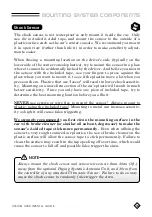
The shock sensor is not waterproof so only mount it 

inside the car

.  Only 

use 

the  included

  2-sided  tape,  and  mount  the  sensor  to  the  outside  of  a 

plastic surface such as the car’s center console.  We recommend you mount 

it in open view (rather than hide it) in order to make sensitivity adjust-

ments easier.  

When  chosing  a  mounting  location  on  the  driver’s  side  (typically  on  the 

lower side of the center console plastics), try to mount the sensor in a place 

where it cannot be accidentally kicked by the driver.  And before you mount 

the  sensor  with  the  included  tape,  use  your  fingers  to  press  against  the 

place where you want to mount it, to see if the plastics move a lot when you 

press on them.  Plastics that are “looser” will result in lower shock sensitiv-

ity.  Mounting on a more firm section of the car’s plastic will result in much 

better sensitivity.  Since you only have one piece of included tape, try to 

determine the best mounting location before you affix it.

NEVER

  use  screws  or  wire  ties  to  mount  the  sensor!    Always  mount  to 

plastic, using the included tape!  Mounting to metal can increase sensitiv-

ity so high it will cause false triggering.  

We strongly recommend

 you first 

clean

 the mounting surface in the 

car with 

brake cleaner

 (or similar oil solvent, degreaser) to make the 

sensor’s 2-sided tape stick more permanently.

  Even when affixing the 

sensor to very rough textured car plastics, the use of brake cleaner on the 

plastic surface will allow the sensor tape to stick permanently. Failure to 

clean the surface may result in the tape peeling off over time, which would 

cause the sensor to fall off and possible false trigger the siren.  

Shock Sensor

Always mount the shock sensor and sensor wires more than 30cm (1ft.) 

away from the optional Paging System’s Antenna Unit, and 30cm from 

the controller of any attached Ultrasonic Sensor.  Failure to do so may 

cause the shock sensor to randomly false trigger the siren.

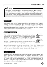
       NOTE

VISION

IR S

HOCK SE

NSOR

Summary of Contents for VISION 1480 Series

Page 1: ... 2011 2020 KIRAMEK INC Aichi Japan Ver 2 6 JUN 2020 DIGI LINK SMART FACTORY KEYLESS UPGRADE SECURITY 1480 series ...

Page 2: ...em The 1480 is a state of the art device that will pro vide you with years of trouble free ser vice if used properly Please familiarize yourself with the content of this Owner s Guide to get the most out of your new system We trust you will enjoy using the product ...

Page 3: ...nd features are subject to change without notice TABLE OF CONTENTS Limited Lifetime Warranty 1 Included Items 2 Arming Disarming 3 Arming 3 Confirmation Chirps 3 Disarming 4 Manual Disarming 5 Main Features 6 Trunk Release Bypass 6 Door Trigger 6 2 Stage Shock Sensor 6 Ignition Trigger 7 Hood Trigger 8 Error Chirp 8 GWA Ground When Armed 8 SBS Sector Bypass System 8 Status LED 9 Hazard Flash 10 Re...

Page 4: ...ar accidents improper use neglect faulty wiring incorrect installation modification removal or defacement of the product serial number alteration or repair outside Kiramek Inc or its Authorized VI SION Dealers immediately voids this warranty This warranty is limited to defective parts only and does not provide any compensation whatsoever for damages associated with the VISION 1480 system or its ac...

Page 5: ...Guides 2pc VISION IR SHOCK SENSOR Only 1480B includes keys FAC TOR Y KEY LESS UPG RAD E SEC URI TY 1480 se ries DIGI LINK SMA RT 25cm Wire Ties 2pcs PosiTap Connectors 4pcs PosiLock Connector 1pc RED p n NT 4 Dark RED p n NL 1 See Installation Guide pg 11 Siren connection See Note below NOTE 4 PosiTap connectors are not included when ordering the 1480 with an optional OB 22W or OB 23W OBD splitter...

Page 6: ...mporarily disable the Shock Sensor for a single Arming session 1 With Ignition OFF press the Program Switch twice 2 Within 20s press LOCK on the factory remote to Arm The siren will chirp 2 times and all triggers door IG etc will be active except the shock sensor and any other external sensors Note that when you Disarm and then Arm again normally the shock sensor will be enabled ON by default This...

Page 7: ...n the middle attacks relay your keyless remote s signal from a dis tance to steal your car You can prevent relay attacks by enabling Feature No 2 shown in TABLE 2 on pg 11 NOTE If your factory remote has only a single Lock Unlock toggle button your car is safe from Relay Attacks THWART RELAY ATTACKS UNLOCK DISARMING DURING THE SIREN BLAST If the siren is triggered by the opening of a door or the b...

Page 8: ...e turned on with out the presence of the Factory Remote So if you lose or destroy your car s remote you may not be able to Manually Disarm the 1480 But if your remote s battery merely dies you will be able to switch on the Igni tion and Manually Disarm using the 4 steps above NOTES DISARM CODE CUSTOMIZATION The factory code is 6 but you should change it to another number between 1 30 1 With the 14...

Page 9: ... The siren will blast for 30s when any door is opened while the system is Armed Vehicle hazard lights may also flash See bottom half of page 4 on how to Disarm in this case Also see Table 1 pg 9 DOOR TRIGGER 2 STAGE SHOCK SENSOR 1st Stage Warning Chirps Each time the Shock Sensor detects a light impact to the vehicle body the si ren will chirp 5 times Sensors will not trigger the siren while in Se...

Page 10: ...The function of IIP is to temporarily switch back to IG Protect Mode after a siren trigger Purpose Most remote start turbo timer compatible car alarms by pass all trigger inputs after the Ignition is switched ON So if a thief opens a door the siren will trigger but the thief can then close the door turn on the Ignition wait until the siren stops then drive away in si lence because the Ignition ON ...

Page 11: ...e TRUNK are bypassed after triggering the siren 10 times IGNITION If the Ignition is left ON the siren blasts up to 10 times 30s each time and then the Ignition is bypassed until you Disarm Arm again SENSOR Warning triggers 5 chirps and Full Triggers 30s siren are independently bypassed after 10 times You must Disarm and then Arm again to re activate SBS Sector Bypass System OFF HOOD TRIGGER On co...

Page 12: ... 3 triggers Trigger Memory will displayed repeatedly on the LED until the Ignition is switched ON or until you Arm again STATUS LED TABLE 1 Status LED Trigger Memory LED Flashes What Triggered the Siren 2 Door 3 Trunk or back hatch 4 Hood see Note below 6 Ignition 7 Sensor Full Trigger only There are no LED Flashes if the power is cut and then restored On most cars Hood triggers detected by CAN BU...

Page 13: ...over your car keys to a valet or car main tenance technician there s no worry they will trigger the siren by accident 1480B NOTE You may wish to disable the battery backup siren with your key Activation With the Ignition switched OFF and the 1480 Disarmed press and hold the Program Switch for more than 5s When you first press the switch the LED will im mediately light But the LED will turn OFF aft...

Page 14: ...ere is no Toggle Setting indication so test to confirm your programming 1 To program another feature repeat the 5 steps above 2 To RESET everything to factory defaults perform the CAN Signal Learning procedure on page 14 of the Installation Guide But be sure to read the NOTE there first NOTES TABLE 2 Feature Selection Menu No Feature Description Toggle Settings 2 Require 2 Unlocks to Disarm Toyota...

Page 15: ...set to RSCM Remote Start Compatibility Mode the system will by pass the Shock Sensor and Ignition triggers when the Ignition turns ON while Armed as described on page 7 3 Ignition Trigger You cannot Arm if IG is ON in IG Protect Mode 2 Require 2 Unlocks to Disarm OFF by default Set to ON to stop Keyless Relay Attacks When ON press ing Unlock only 1 time will NOT Disarm To Disarm you must press Un ...

Page 16: ... will be Armed and will trigger if a door is opened 8 Auto Arm When set to ON vehicle hazard lights will flash for safety only on com patible cars when a door is opened or left open while the Ignition is ON Flashing will stop when the door is closed or Ignition is switched OFF NOTE The Status LED will always flash when the Ignition is ON and a door open in order to notify the driver This LED flash...

Page 17: ...on most cars so to add Speed Lock in that case please purchase an SL series Speed Lock product NOTES Many cars have a relock feature if you Unlock with your factory re mote the car will automatically relock the doors after some time has elapsed if no door has been opened If your car has auto relock and if the 1480 Arms on relock then you do not need to enable Auto Rearm NOTE If set to ON after you...

Page 18: ... Sensor Bypass Mode See page 3 SIREN BLASTS WHEN THE TRUNK IS OPENED You cannot open the trunk with the key or the siren will sound Use your factory remote If your keyless remote doesn t have a trunk open feature then you need to Disarm the system first Unlock button on your factory remote and then open the trunk If you open the trunk with your factory remote and the siren triggers it could be the...

Page 19: ...y that the controller of the ultrasonic sensor not the emitters was placed too close to the shock sensor The Ultrasonic sensor s controller should be placed more than 30cm 1 foot away from the shock sensor to avoid interference HOOD TRIGGERS SIREN BUT TRIGGER MEMORY REPORTS DOOR HOOD Some Mercedes and BMW cars send a digital door open mes sage on the CAN when the Hood is opened On these cars if th...

Page 20: ... 2011 2020 KIRAMEK INC Aichi Japan Ver 2 0 JUN 2020 DIGI LINK SMART FACTORY KEYLESS UPGRADE SECURITY 1480 series ...

Page 21: ...N installer All product warranties im mediately become void if the 1480 is not in stalled by an authorized dealer If you acquired this product without profes sional installation DO NOT install it yourself to save a little money at the risk of damaging your vehicle or causing physical injury ...

Page 22: ...Input 13 CAN Signal Learning 14 Mounting System Components 15 Adjusting the Shock Sensor 17 Troubleshooting 18 Options 20 NOTE Consult Owner s Guide page 11 for Feature Programming NOTICE Although reasonable efforts have been taken to ensure accuracy in this Ana log Install Guide Kiramek Inc shall not be held liable for any errors omissions prop erty damage or injury resulting from the use of this...

Page 23: ...e s battery 3 Do not proceed with installing this system in vehicles that do not have a 12 volt electrical system This system will not function in 24 volt trucks and any damage resulting from such installation shall be the sole responsibility of the installer 4 Do not install the 1480 control module or associated sensors in or near water or in a location where water could gather The 1480 is not wa...

Page 24: ...ive circuitry in the vehicle Manually turn off all lights such as the dome light that illuminate when a hatch is opened so you will not run down the battery If you can not manually turn off all the lights then remove the appropriate fuses and don t forget to replace the fuses after your installation is complete Roll down a window to avoid locking the keys in the car If unsure consult the vehicle o...

Page 25: ...dness Audio Generator Housing Certification Replacement P N 12Vdc 5 5mA 1480B trickle charge or 0mA 1480S 1A max during full siren blast 40 C to 125 C 125dB measured 30cm 1ft from speaker 1 tone 6 tone selectable by cutting loop on siren Water resistant cannot be submerged IP54 KB22 1 1480B or KR22 1 1480S Shock Sensor Operating Voltage Current Consumption Operating Temp Sensor Technology Certific...

Page 26: ...ITY 1480 DIGI LINK SMART Guides 2pc FAC TOR Y KEY LESS UPG RA DE SEC URI TY 1480 se ries DIGI LINK SMA RT PosiTap Connectors 4pcs RED p n NT 4 PosiLock Connector 1pc Dark RED p n NL 1 Only 1480B includes keys See Note below NOTE 4 PosiTap connectors are not included when ordering the 1480 with an optional OB 22W or OB 23W OBD splitter harness because they are not needed But 1 PosiLock connector is...

Page 27: ...ted the four CAN Power wires OBD plug and the Siren wire pages 6 12 you will need to perform the CAN Signal Learning steps on page 14 You must do the CAN Learning steps even though the 1480 has been programmed with firmware matched to your car ELECTRICAL CONNECTIONS The 1480 s OBD plug containing 2 Power wires 2 CAN wires is the most critical connection you will make If you do not wish to use the ...

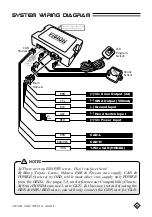
Page 28: ...atibility Charts 3 Some HONDA cars use 1 wire CAN In this case instead of using the BRN BRN RED wires you will only connect the GRN wire for CAN NOTES Two connectors on back are for firmware programming only RED Optional Pager 5A Fuse BRN YEL GWA Output 500mA BLK Ground Input GRY Hood Switch Input RED 12v Power Input 12v Siren Output 2A BRN BRN RED CAN H GRN 1 Wire CAN HONDA CAN L LED Program Swit...

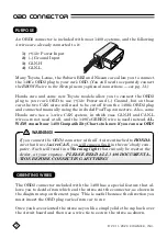
Page 29: ...s use a 1 wire CAN system in which case CAN H and CAN L wires are not used at all and the 1480 s GREEN wire is used instead AL WAYS consult our 1480 Compatibility Charts to know if you can use OBD The OBD2 connector included with the 1480 has a special feature that al lows you to decide from which end the wires exit the connector as shown in the diagram atop on the next page This is useful because...

Page 30: ...t the Siren pg 11 and then finish with the LEARNING STEPS pg 14 Hiding the OBD connection is pos sible by cutting off the 1480 s OBD plug and manually connecting the 4 wires be hind the vehicle s OBD using the includ ed PosiTap connectors or by purchasing an optional OB 22W or OB 23W splitter harness see pg 2 note under PosiTaps For all cars where OBD cannot be used please consult our separate ve ...

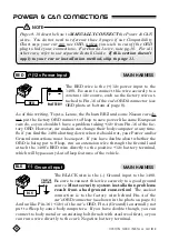
Page 31: ...hich will bypass any Auto Sleep features of the vehicle MAIN HARNESS MAIN HARNESS Pages 9 10 describe how to MANUALLY CONNECT the Power CAN wires You do not need to reference these 2 pages if our Compatibility Chart says your car can use OBD unless you wish to cut off the OBD plug to hide your connections For Honda 1 wire note pg 10 For all other cars refer to our separate Install Guide If this se...

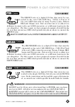
Page 32: ... reason we have prepared separate Install Guides for cars that cannot use OBD which provide details on where to connect the BROWN wire DON T CONFUSE CAN L WITH THE BROWN SIREN OUTPUT The GREEN wire is a digital I O line that must be con nected to the single CAN line but only on certain HONDA cars Such connections are beyond the scope of this manu al so consult our vehicle specific Install Guide fo...

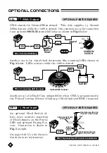
Page 33: ...en Connections Cut Blue Loop for 6 tone sound BRN Dark Red PosiLock MAIN HARNESS BLUE LOOP BRN ORG FIG 1 1480S Siren Connections Cut Blue Loop for 6 tone sound RED Dark Red PosiLock MAIN HARNESS BLUE LOOP STANDARD SIREN BRN One PosiLock connector is included for connecting the 1480 s Brown Siren Output If you use the included OBD for Power CAN you will have 4 PosiTap connectors left over Although ...

Page 34: ...ly will lose the backup function The 1480B comes with a Battery Backup Siren and two siren keys At the factory the siren is Disabled so it will not make any sound until you Enable it by switching the keylock to the GREEN dot position as shown at right Keep the siren Disabled until you have made all your con nections otherwise the siren may trigger Be sure to keep your keys in two separate safe pla...

Page 35: ...R 1 required An optional Hood Switch al lows more accurate reporting of Hood triggers on the Status LED and optional Paging Sys tem Connection is shown in Fig 5 at right See pages 9 15 in the Owner s Guide for more information OPTIONAL PARTS REQUIRED OPTIONAL PARTS REQUIRED YEL GRY GWA Output Hood Input IGNITION SWITCH STARTER OFF ACC ON ST PUR cut BLU FIG 3 Starter Kill Wiring YEL 896H 1B RELAY 8...

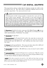
Page 36: ...mes 5 Switch OFF the Ignition The LED may or may not stay lit and or flash a few seconds 6 Lock and Unlock Vehicle CAN signals are now learned Wait 20 seconds before you Lock again otherwise you may enter Sensor Bypass Mode see pg 3 in the Owner s Guide for details of that mode NOTE If the above steps do not work i e the 1480 won t function you may need to start the engine in Step 2 above rather t...

Page 37: ...s Control Module LED Program Switch Find a location in the engine compartment such as the firewall that is far from heat sources or moving parts such as belts or the radiator fan Locate a factory bolt or bolt hole for securing the siren mount otherwise you will need to drill holes and use self tapping screws Mount in a place that will not be splashed excessively with water or immersed in water Sir...

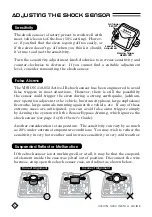
Page 38: ...ty Since you only have one piece of included tape try to determine the best mounting location before you affix it NEVER use screws or wire ties to mount the sensor Always mount to plastic using the included tape Mounting to metal can increase sensitiv ity so high it will cause false triggering We strongly recommend you first clean the mounting surface in the car with brake cleaner or similar oil s...

Page 39: ... siren triggers simply by Arming the system with the Sensor Bypass Arming which ignores the shock sensor see page 3 of the Owner s Guide Another consideration is temperature The sensitivity can vary by as much as 20 under extreme temperature conditions You may wish to reduce the sensitivity in very hot weather and increase sensitivity in very cold weather False Alarms If the shock sensor is not wo...

Page 40: ...ng the OBD connector on a car other than Toyota Nissan Subaru BRZ or Lexus If so it will not work At this time we do not sup port OBD connections on cars other than Toyota Nissan Lexus BRZ If all else fails try the following ALTERNATE CAN LEARNING STEPS instead of those given on page 14 1 Disconnect the white 6 cavity connector of the Main Harness OR re move the Fuse on the Red 12v power line The ...

Page 41: ...tivity of the shock sensor If the Green LED lights perhaps you re testing too quickly After Lock ing Arming you must wait 10s before you can test the shock sensor SHOCK SENSOR GIVES REPEATED WARNING TRIGGERS If the sensitivity of the sensor is too high and or if the mounting location is incorrect the sensor may be triggering on the otherwise undetectable sounds of the hazard light relay switching ...

Page 42: ...drive high current devices like the Horn S 114R or S 113 Pin switch to detect Hood opening OB 22W or OB 23W OBD splitter harnesses useful for simply hiding the 1480 s OBD connection OB 22W or hiding the connection AND add ing a 3rd party OBD device OB 23W Some 3rd party OBD devices may be incompatible with the 1480 Contact KIRAMEK for details Optional Sensors MMF 2 2 stage Radar Sensor KST 24 2 st...

Page 43: ...Aichi Ken 475 0936 JAPAN TEL 81 569 20 5585 FAX 81 569 20 5586 EMAIL support kiramek com VISION products are engineered in Japan and manufactured in strict accordance with Japanese QC standards at an ISO9000 QS9000 certified factory ...

Reviews: