


Electrical Protection For Smart Instruments & DustIQ V3.0
Page
2
of
3
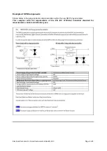
RS-485 requires that a 120 Ohm termination resistor is fitted across the data lines at the data
acquisition port, this I because the impedance of a twisted pair data cable is typically in the range of
100-150 Ohms.
Whether pull-up and pull-down bias resistors are required depends on the cable length and the bus
topography (number of devices connected and in what layout) and the ideal resistor value depends
upon the data line voltages. 470 Ohms or 680 Ohms are typically used. These resistors are connected
between each data line and the RS-
485 ‘common’. For more than about 50 m of cable, it is usually
necessary to have the correct bias resistors at the data acquisition port end and a 120 Ohm
termination resistor at the instrument.
With the correct configuration, as above, communication should work reliably at 19,200 baud up to
1000 m with one device connected. It might be necessary to lengthen the poll/response delay timeout
limit at the data acquisition. If multiple devices (with different addresses, of course) are connected to
one RS-485 data acquisition input settings depend upon the topography of the network (how the
devices are connected) and it may be necessary to reduce the baud rate and increase the polling
interval.
RS-485 Modbus® RTU Surge Protection
SMP12 and DustIQ, with PV module temperature sensor and integrated tilt angle sensor, have surge
protection built-in for both RS-485 lines, but they are not electrically isolated. The best protection is to
provide an isolation module as close as is practical to the instrument.
The other Smart instruments have only common mode voltage protection for the line driver; up to 70
VDC. It may be damaged by accidentally applying power to the connections. It is strongly advised to
use an industrial surge protection device (SPD), installed as close as is practical to the instrument.
Ideally, this should be electrically isolated.
Analog Output
The analog outputs of the Smart instruments only have short-circuit protection, accidentally applying
power to the connections will damage the voltage or current output amplifier.
It is strongly advised to use an industrial surge protection device (SPD), installed as close as is
practical to the instrument, ideally with electrical isolation.
Grounding
ESD and surge protection depends upon a good earth/ground connection to conduct away the
induced current. In many cases there is not a good connection through the instrument mounting as the
aluminium housing parts are anodised. The cable shield is connected to the housing internally and this
needs to be grounded close to the instrument. Note that shield is the thick black wire in the yellow
instrument cable.
Ideally, the shield would be grounded through an earth spike close to the mounting point or field wiring
junction box. This is also where any surge protection devices should be located and grounded. Do not
also connect the shield at the data acquisition end.
If the shield is only connected at the data acquisition end, ensure that the connection point is a
protective earth/ground and not a ‘0 V’ or power supply ‘-‘ terminal.
Note: If there is a longer cable than needed it is better to shorten it (leaving a loop for water to drip off)
than to coil it up. This will minimise electrical pick-up.


