29
12.8
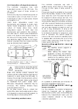
Temperature sensors checking
Temperature sensors can be checked by
measuring
their
resistance
in
given
temperature. In case of big differences
between measured resistance value and
values in table below, the sensor should be
replaced with a new one.
CT4
Temp.
°C
Min.
Ω
Nom.
Ω
Max.
Ω
0
802
815
828
10
874
886
898
20
950
961
972
25
990
1000
1010
30
1029
1040
1051
40
1108
1122
1136
50
1192
1209
1225
60
1278
1299
1319
70
1369
1392
1416
80
1462
1490
1518
90
1559
1591
1623
100
1659
1696
1733
CT4-P (weather)
Temp.
°C
Min.
Ω
Nom.
Ω
Max.
Ω
-30
609
624
638
-20
669
684
698
-10
733
747
761
0
802
815
828
10
874
886
898
20
950
961
972
CT6-P (weather)
Temp.
°C
Min.
Ω
Nom.
Ω
Max.
Ω
-25
901,6
901,9
902,2
-20
921,3
921,6
921,9
-10
960,6
960,9
961,2
0
999,7
1000,0
1000,3
25
1096,9
1097,3
1097,7
50
1193,4
1194,0
1194,6
100
1384,2
1385,0
1385,8
12.9
Optical sensor connection
The optical sensor should be connected in
accordance with point 12.5, be sure to
observe the polarization of the (+) and (-)
sensor signals. Readings of data from optical
sensor is possible in the menu:
Information
→
Flame
Incorrect connection of the optical
sensor
will
not
damage
the
controller or the sensor itself, but
the burner flame detection will be
incorrect.
12.10
Mixers room temperature
connection
Room thermostat, connected to module B,
after disconnecting contacts reduces preset
temperature of the value of reduction the
preset temperature of the mixer from the
thermostat. Parameter is in the menu:
Mixer settings 1-2
→
Mixer room
temperature
Value of parameter should be chosen in such
a way that after activating room thermostat,
temperature in the room should decrease. In
case of room panel make sure that this
parameter
Thermostat select.
is correctly
chosen in the menu:
Service settings
→
Mixer settings 1-2
12.11
Connection of reserve boiler
The controller can control a reserve boiler
(gas- or oil-fired), eliminating the necessity
of enabling or disabling this boiler manually.
Connection to a reserve boiler, e.g. oil-fired
one, should only be made by a qualified
fitter, in accordance with the technical
documentation of this boiler. The reserve
boiler
should
be
connected
via
relay to terminals 30-31 additional B module.
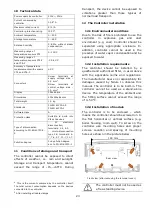
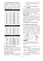
An example of a reserve boiler connection scheme: 1
–
additional B module, 2
–
reserve boiler (gas- or oil-), 3
–
relay 6 VDC
.
Standard version of the controller is not
equipped with a relay.
Assembly of relay should be
done by a person with proper
qualifications. According to valid
norms and regulations.
To enable the control of reserve boiler, set
the H output (mod B) to operate the
Reserve
boiler
in the menu:
B
Summary of Contents for ecoMAX360P1-C
Page 6: ...6 ...
Page 7: ...USER SETTINGS ecoMAX360P1 C ...
Page 18: ...18 ...
Page 19: ...19 INSTALLATION AND SERVICE SETTINGS ecoMAX360P1 C ...
Page 42: ...42 ...
Page 43: ...43 ...


