background image

Chapter 3   Error Correction 

3-10

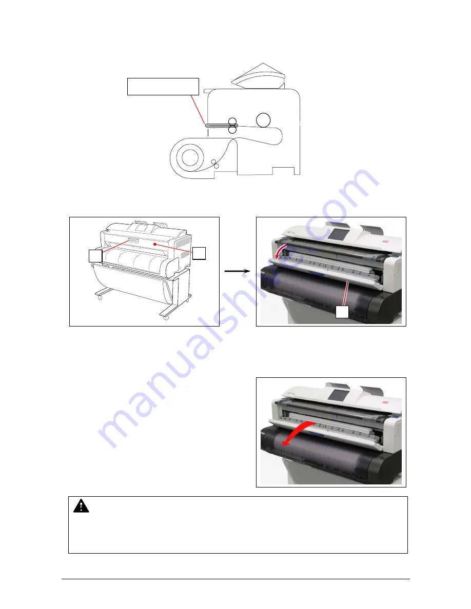
3. 1. 4     J-0106 / 0206   Fuser section 

 
Remove a mis-feed media in the Fuser section if the UI screen will show J-0106 or 0206. 


1. Hold the blue handle (1) and open the Exit Cover (2). 


2. If it is possible, pull and remove the mis-feed media. 
 

If little amount of the leading edge area is coming to the Fuser and you cannot pull it out,  
or if the trailing edge remains deep to be caught in the printer, do not pull it by force.  
Leave it there and go to the next step. 


J-0106 or J-0206 


WARNING 

 
There are extremely hot parts inside the Fuser Unit. Do not touch any parts in the Fuser Unit, 
or you will be burnt. 
Also the mis-fed media can be very hot. Be careful not to get burnt when you remove it. 

2

Summary of Contents for 700m

Page 1: ...Version A3 KIP 700m User Manual...

Page 2: ...pment such as noise or flickering may occur Use a separate power line and install the PRINTER as far as possible from said equipment The International ENERGY STAR Office Equipment Program is an intern...

Page 3: ...ut the USER S Manual and have the following meaning WARNING This WARNING mark means that there is a possibility of death or serious injury if you ignore or do not follow the said instruction CAUTION T...

Page 4: ...r placing heavy items on it If the Power Cord is damaged it may cause a fire or you may receive an electric shock REPLACE THE CORD IF DAMAGED 1 Do not put a flower vase a flowerpot or any water filled...

Page 5: ...an unstable floor as injuries may occur 1 Unplug the printer before you move it The power cord may be damaged and it may result in a fire or electric shock 2 If you do not use the printer for a long...

Page 6: ...pin or terminal If the appropriate plug does not fit the wall outlet in the installation the customer shall install an appropriate outlet Connector Type Configuration Standard Rating Usually found in...

Page 7: ...ions 1 5 1 4 1 General 1 5 1 4 2 Printer part 1 7 1 4 3 Scanner part 1 8 1 5 Appearance 1 9 1 5 1 Front view 1 9 1 5 2 Rear view 1 10 1 6 Specifications for the Scan Original 1 11 1 7 Specifications f...

Page 8: ...ter away from water sources boilers humidifiers or refrigerators 1 The installation site must not have open flames dust or ammonia gases 2 The equipment must not be exposed to the air vents from air c...

Page 9: ...ding that some specific company copies such originals as many as it requires for its own business 2 We recommend you not to copy freely such originals as government issued passport public or private i...

Page 10: ...s 2 9 D landscape 2 8 A1 landscape per minute 6 The maximum print width is 914mm 36 wide and the minimum one is 210mm or 8 5 The maximum print length is 2 400mm for A0 36 wide media and the minimum o...

Page 11: ...impulse sound excluded EN ISO 7779 Ozone Max 0 05ppm Measurement method under UL Standard Dimensions 1245mm Width x 833mm Depth x 1174mm Height including Stand Weight About 144kg 318lbs Stand exclude...

Page 12: ...Standard length vellum tracing paper film Option 3 600mm Minimum 297mm 11 Print size from Paper Tray option ISO mm Width Length ANSI inch Width Length Warm up time Shorter than 2 minutes 30 seconds At...

Page 13: ...4MIL 4Mil 2 Xero Film Europe Asia model Plain Paper 64g m2 to 80g m2 Oce Red Label Paper 75g m2 Tracing Paper Oce Transparent Paper 80g m2 Film Oce Polyester Film 2 roll core HP Universal Bond Paper...

Page 14: ...Including the margin area Min 210mm 8 5 Including the margin area Margin area 3mm from leading trailing and both side edges Optical resolution 600dpi Digital resolution 200 300 400 600 dpi Original t...

Page 15: ...feed it into the Scanner Unit when you make scan or copy 7 Engine Unit Open Lever Push down these blue levers when you open the Engine Unit 8 Bypass Feeder Feed a cut sheet paper from the Bypass Feede...

Page 16: ...Unit 3 LAN Port Connect the LAN Cable to connect the KIP 700m to the network Do not connect a telephone line 4 USB Port Service Use 5VDC max 5 Breaker It is possible to shut off supplying the AC power...

Page 17: ...mm to 1 6mm Width 279 4mm to 914 4mm Length 210mm to 6 000mm If an original is thicker than 0 65mm its image quality is not guaranteed even it is transported Do not scan the following kinds of origina...

Page 18: ...pter 1 Before Use 1 12 Not square Wet Metal or fabric material Rough surface Carbon paper for example Clipped or stapled K I P K I P K I P K I P K I P K I P Wet Metal Fabric Clipped Stapled Rough surf...

Page 19: ...Chapter 1 Before Use 1 13 The following kinds of originals can be read with using a carrier sheet Image quality or the reliability of paper feeding for them is not guaranteed Patched Punched...

Page 20: ...pecifications for the Printing Paper 1 7 1 Papers not available to use Do not use the following kinds of printing paper Doing so may damage the print engine Excessively curled a diameter of 50 mm or l...

Page 21: ...rint image may become defective if the print paper has an excess curl 3 It will cause paper mis fed poor print image or creasing if you use a paper that does not satisfy the specifications 4 Do not us...

Page 22: ...ine after everyday use and keep it in a polyethylene bag Void of image occurs when you print with plain paper and tracing paper If you will not make print soon remove the tracing paper from the machin...

Page 23: ...ning on KIP 700m 2 2 2 2 Turning off KIP 700m 2 4 2 3 Replacing Roll Media 2 5 2 4 Initial Cut 2 9 2 5 Toner Supply 2 10 2 6 Cut Sheet Media 2 13 2 7 Copying 2 14 2 8 Emergency Stop of Scan or Copy 2...

Page 24: ...WARNING 1 Do not handle the Power Plug with wet hands or you may receive an electrical shock 2 Make sure to earth the machine for safety 3 Do not plug the printer into a multi wiring connector in whic...

Page 25: ...n Copy Mode Screen will flash during warming up The UI screen may vary depending on your system configuration Shown with available options 4 When Ready Indicator stops flashing the KIP 700m is ready f...

Page 26: ...ress side CAUTION The KIP 700m print engine and UI appear to be shut down when you turn off KIP 700m However the controller PC embedded inside the KIP 700m is still operating and will shutdown in appr...

Page 27: ...pty roll core 3 2 Raise the green lever 4 on Flange 2 Remove both Flanges 2 from the roll core 3 3 Move the right Slide Guide 5 to match your roll media s width The right and left Slide Guides move to...

Page 28: ...r way Position them flat against Flange to secure the roll media NOTE 1 Fully insert Flange into the roll media core so that the inside rim of Flange evenly touches the side face of the roll media Cor...

Page 29: ...to Slide Guides 5 in Roll Deck NOTE 1 Be careful of the winding direction of the roll media 2 The outside rim of Flange 2 should fit into the groove on the Slide Guide Otherwise the roll media may fal...

Page 30: ...es the feeding rollers 6 After that the leading edge will automatically go into the roll media s wait position This is called Auto Media Loading 8 Trim the leading edge of the roll media with Initial...

Page 31: ...e right 3 The leading edge of the roll media is automatically transported and cut off Remove the portion of the media 3 and close the Manual Feeder Table 1 1 2 3 Reference 1 Initial Cut is a function...

Page 32: ...ch 1 on the rear top You do not have to remove the Original Guide 2 Shake the Toner Bottle 2 several times to loosen the toner NOTE After you shake the Toner Bottle well proceed the later step 3 and 4...

Page 33: ...Chapter 2 Basic Operation 2 11 3 Put the dent area 3 under the holder 4 to firmly seat the bottom plate of the Toner Bottle 2 to the toner supply position 4 2 4 from right from front 3 from front...

Page 34: ...original position Remove the Toner Bottle NOTE It is impossible to remove the Toner Bottle unless the lever 5 completely moves to the original position Do not attempt to remove the Toner Bottle by for...

Page 35: ...Chapter 2 Basic Operation 2 13 6 Close the Toner Hatch 1 7 Press OK button on the UI screen OK 1...

Page 36: ...edge touches the feeding roller the printer automatically carries and sets the paper at the proper position NOTE 1 As a curly cut sheet will cause a mis feed straighten the sheet as far as possible be...

Page 37: ...the original on the Original Table with face up Then insert it under the Scanner Unit along with Original Guides When the leading edge touches the original feeding roller the machine automatically car...

Page 38: ...Scanner Unit to immediately stop the original while making a copy or scan Pressing the button stops the current reading a document immediately The current printing is stopped as well and is ejected 1...

Page 39: ...t after a 60 minute of inactivity to stop the power supply for Fuser Unit and some other components Sleep Mode is canceled and the machine gets ready when the machine receives a print job through the...

Page 40: ...Media Feed section 1 3 5 3 1 4 J 0105 0205 Media Feed section 2 3 7 3 1 5 J 0106 0206 Fuser section 3 9 3 1 6 J 1300 1400 Door Open while printing 3 12 3 1 7 Original Jam 3 14 3 2 Other Operator Call...

Page 41: ...wing figure to check the jam location Mis feed Codes are described on the later pages NOTE 1 Be careful not to get paper cuts on your hand 2 It is recommended to take off your ring bracelet or watch w...

Page 42: ...1 Open the Roll Deck Cover Rewind the roll onto the media core 2 Rotate the roll media in the arrow direction and insert the leading edge of the roll media to the media path until it touches the feed...

Page 43: ...remain in the media path of the Roll Deck at a roll empty The printer does not show any mis feed error code against the portion So please check for the portion in the media path through the square wi...

Page 44: ...screen will show J 0203 1 Pull out the mis feed cut sheet from the Manual Feeder J 0203 NOTE The mis feed cut sheet should be replaced with a new one if its leading edge has a torn or fold Or it shoul...

Page 45: ...Media Feeder section 1 Remove a mis feed media in the Media Feeder section 1 if the UI screen will show J 0104 or 0204 1 Press down the blue levers 1 on both sides to unlock and open the Upper Unit 2...

Page 46: ...Chapter 3 Error Correction 3 7 3 Put your hands on the rear rim of the scanner unit just as you hold the Upper Unit Push the entire unit down to the arrow direction Hold here Hold here...

Page 47: ...Media Feeder section 2 Remove a mis feed media in the Media Feeder section 2 if the UI screen will show J 0105 or 0205 1 Press down the blue levers 1 on both sides to unlock and open the Upper Unit 2...

Page 48: ...Chapter 3 Error Correction 3 9 3 Put your hands on the rear rim of the scanner unit just as you hold the Upper Unit Push the entire unit down to the arrow direction Hold here Hold here...

Page 49: ...ia If little amount of the leading edge area is coming to the Fuser and you cannot pull it out or if the trailing edge remains deep to be caught in the printer do not pull it by force Leave it there a...

Page 50: ...Chapter 3 Error Correction 3 11 3 Press down the blue levers 3 on both sides to unlock and open the Upper Unit 4 Remove the mis feed media 5 Close the Exit Door 3 3...

Page 51: ...Chapter 3 Error Correction 3 12 6 Put your hands on the rear rim of the scanner unit just as you hold the Upper Unit Push the entire unit down to the arrow direction Hold here Hold here...

Page 52: ...and remove the mis feed media If little amount of the leading edge area is coming to the Fuser and you cannot pull it out or if the trailing edge remains deep to be caught in the printer do not pull i...

Page 53: ...is feed media If the mis feed media does not exist go to the next step 5 Close the Exit Door 6 Put your hands on the rear rim of the scanner unit just as you hold the Upper Unit Push the entire unit d...

Page 54: ...the media core 8 Rotate the roll media in the arrow direction and insert the leading edge of the roll media to the media path until it touches the feeding rollers 4 After that the leading edge will au...

Page 55: ...truction below to remove the mis fed original 1 On both sides pull the levers 1 under the scanner cover to open the Scanner Unit until it locks 2 Remove a mis feed original 3 Gently press the Scanner...

Page 56: ...oner the UI Screen will display Toner Empty sign For the toner supply procedure see 2 5 Toner Supply 3 2 3 Roll Deck Cover Open If the Roll Deck Cover is open not closed properly the UI screen shows R...

Page 57: ...the customer Error Code E 000 E 001 E 002 E 003 E 005 E 006 E 007 E 010 E 013 E 020 E 031 E 032 E 033 E 034 E 040 E 050 E 070 E 080 E 081 E 090 If any of the above errors appear 1 Turn off KIP 700m a...

Page 58: ...Chapter 4 Maintenance 4 1 Chapter 4 Maintenance page 4 1 Cleaning 4 2 4 1 1 Scanner Unit 4 2 4 1 2 Touch Screen 4 4...

Page 59: ...f these parts are dirty 1 Turn off KIP 700m 2 Press the levers 1 up to unlock the Scanner Unit Open the Scanner Unit 3 Wipe each Scan Glass 2 Pinch Rollers 3 gray and the inside surface of the metal p...

Page 60: ...Rollers 4 gray Press Rollers 5 white and the inside surface with a soft dry cloth 5 Gently press Scanner Unit down and firmly close it NOTE Press down Scanner Unit on both side to close it Do not clos...

Page 61: ...Chapter 4 Maintenance 4 4 4 1 2 Touch Screen 1 Wipe the Touch Screen with a dry cloth NOTE Do not use water alcohol organic solvent and glass cleaner for the cleaning...

Reviews: